With immunotherapy increasingly making it out of the lab and into hospitals as a viable way to treat serious conditions like cancer, there’s a lot of pressure to optimize these therapies. This is especially true for therapies involving chimeric antigen receptor (CAR) T cells, which so far required a cumbersome process of extracting the patient’s T cells, modifying them ex vivo and returning the now CAR T cells to the patient’s body. After a recently published study, it seems that we may see in vivo CAR T cell therapy become reality, with all the ease of getting a vaccine shot.
We covered CAR T cells previously in the context of a way to prevent T cell exhaustion and making them more effective against certain tumors. This new study (paywalled) by [Theresa L. Hunter] et al. as published in Science demonstrates performing the CAR manipulation in vivo using CD8+ T cell targeting lipid nanoparticles containing mRNA to reprogram these T cells directly.
In rodent and non-human primate studies a clear effect on tumor control was demonstrated, with for auto-immune diseases the related B cells becoming effectively depleted. Although it’s still a long way off from human trials and market approval, this research builds upon the knowledge gained from existing mRNA vaccines, raising hopes that one day auto-immune or cancer therapy could be as simple as getting a cheap, standardized shot.
Some Mondays are worse than others, but April 28 2025 was particularly bad for millions of people in Spain and Portugal. Starting just after noon, a number of significant grid oscillations occurred which would worsen over the course of minutes until both countries were plunged into a blackout. After a first substation tripped, in the span of only a few tens of seconds the effects cascaded across the Iberian peninsula as generators, substations, and transmission lines tripped and went offline. Only after the HVDC and AC transmission lines at the Spain-France border tripped did the cascade stop, but it had left practically the entirety of the peninsula without a functioning power grid. The event is estimated to have been the biggest blackout in Europe ever.
Following the blackout, grid operators in the affected regions scrambled to restore power, while the populace tried to make the best of being plummeted suddenly into a pre-electricity era. Yet even as power gradually came back online over the course of about ten hours, the question of what could cause such a complete grid collapse and whether it might happen again remained.
With recently a number of official investigation reports having been published, we have now finally some insight in how a big chunk of the European electrical grid suddenly tipped over.
Oscillations
Electrical grids are a rather marvelous system, with many generators cooperating across thousands of kilometers of transmission lines to feed potentially millions of consumers, generating just enough energy to meet the amount demanded without generating any more. Because physical generators turn more slowly when they are under heavier load, the frequency of the AC waveform has been the primary coordination mechanism across power plants. When a plant sees a lower grid frequency, it is fueled up to produce more power, and vice-versa. When the system works well, the frequency slowly corrects as more production comes online.
The greatest enemy of such an interconnected grid is an unstable frequency. When the frequency changes too quickly, plants can’t respond in time, and when it oscillates wildly, the maximum and minumum values can exceed thresholds that shut down or disconnect parts of the power grid.
In the case of the Iberian blackout, a number of very significant oscillations were observed in the Spanish and Portuguese grids that managed to also be observable across the entire European grid, as noted in an early analysis (PDF) by researchers at Germany’s Friedrich-Alexander-Universität (FAU).
European-wide grid oscillations prior to the Iberian peninsula blackout. (Credit: Linnert et al., FAU, 2025)
This is further detailed in the June 18th report (direct PDF link) by Spain’s Transmission System Operator (TSO) Red Eléctrica (REE). Much of that morning the grid was plagued by frequency oscillations, with voltage increases occurring in the process of damping said oscillations. None of this was out of the ordinary until a series of notable events, with the first occurring after 12:02 with an 0.6 Hz oscillation repeatedly forced by a photovoltaic (PV) solar plant in the province of Badajoz which was feeding in 250 MW at the time. After stabilizing this PV plant the oscillation ceased, but this was followed by the second event with an 0.2 Hz oscillation.
After this new oscillation was addressed through a couple of measures, the grid was suffering from low-voltage conditions caused by the oscillations, making it quite vulnerable. It was at this time that the third major event occurred just after 12:32, when a substation in Granada tripped. The speculation by REE being that its transformer tap settings had been incorrectly set, possibly due to the rapidly changing grid conditions outpacing its ability to adjust.
Subsequently more substations, solar- and wind farms began to go offline, mostly due to a loss of reactive power absorption causing power flow issues, as the cascade failure outpaced any isolation attempts and conventional generators also threw in the towel.
Reactive Power
Grid oscillations are a common manifestation in any power grid, but they are normally damped either with no or only minimal interaction required. As also noted in the earlier referenced REE report, a big issue with the addition of solar generators on the grid is that these use grid-following inverters. Unlike spinning generators that have intrinsic physical inertia, solar inverters can rapidly follow the grid voltage and thus do not dampen grid oscillations or absorb reactive power. Because they can turn on and off essentially instantaneously, these inverters can amplify oscillations and power fluctuations across the grid by boosting or injecting oscillations if the plants over-correct.
In alternating current (AC) power systems, there are a number of distinct ways to describe power flow, including real power (Watt), complex power (VA) and reactive power (var). To keep a grid stable, all of these have to be taken into account, with the reactive power management being essential for overall stability. With the majority of power at the time of the blackout being generated by PV solar farms without reactive power management, the grid fluctuations spun out of control.
Generally, capacitors are considered to create reactive power, while inductors absorb it. This is why transformer-like shunt reactors – a parallel switchyard reactor – are an integral part of any modern power grid, as are the alternators at conventional power plants which also absorb reactive power through their inertia. With insufficient reactive power absorption capacity, damping grid oscillations becomes much harder and increases the chance of a blackout.
Ultimately the cascade failure took the form of an increasing number of generators tripping, which raised the system voltage and dropped the frequency, consequently causing further generators and transmission capacity to trip, ad nauseam. Ultimately REE puts much of the blame at the lack of reactive power which could have prevented the destabilization of the grid, along with failures in voltage control. On this Monday PV solar in particular generated the brunt of grid power in Spain at nearly 60%.
Generating mix in Spain around the time of the blackout. (Credit: ENTSO-E)
Not The First Time
Despite the impression one might get, this wasn’t the first time that grid oscillations have resulted in a blackout. Both of the 1996 Western North America blackouts involved grid oscillations and a lack of reactive power absorption, and the need to dampen grid oscillations remains one of the highest priorities. This is also where much of the criticism directed towards the current Spanish grid comes from, as the amount of reactive power absorption in the system has been steadily dropping with the introduction of more variable renewable energy (VRE) generators that lack such grid-stabilizing features.
To compensate for this, wind and solar farms would have to switch to grid-forming inverters (GFCs) – as recommended by the ENTSO-E in a 2020 report – which would come with the negative effect of making VREs significantly less economically viable. Part of this is due to GFCs still being fairly new, while there is likely a strong need for grid-level storage to be added to any GFC in order to make especially Class 3 fully autonomous GFCs work.
It is telling that five years after the publication of this ENTSO-E report not much has changed, and GFCs have not yet made inroads as a necessity for stable grid operation. Although the ENTSO-E’s own investigation is still in progress with a final report not expected for a few more months at least, in light of the available information and expert reports, it would seem that we have a good idea of what caused the recent blackout.
The pertinent question is thus more likely to be what will be done about it. As Spain and Portugal move toward a power mix that relies more and more heavily on solar generation, it’s clear that these generators will need to pick up the slack in grid forming. The engineering solution is known, but it is expensive to retrofit inverters, and it’s possible that this problem will keep getting kicked down the road. Even if all of the reports are unanimous in their conclusion as to the cause, there are unfortunately strong existing incentives to push the responsibility of avoiding another blackout onto the transmission system operators, and rollout of modern grid-forming inverters in the solar industry will simply take time.
In other words, better get used to more blackouts and surviving a day or longer without power.
Some of the largest objects in the night sky to view through a telescope are galaxies and supernova remnants, often many times larger in size than the moon but generally much less bright. Even so, they take up a mere fraction of the night sky, with even the largest planets in our solar system only taking up a few arcseconds and stars appearing as point sources. There are more things to look at in the sky than there are telescopes, regardless of size, so it might almost seem like an impossible task to see everything. Yet that’s what this new telescope in Chile aims to do.
The Vera C. Rubin Observatory plans to image the entire sky every few nights over a period lasting for ten years. This will allow astronomers to see the many ways the cosmos change with more data than has ever been available to them. The field of view of the telescope is about 3.5 degrees in diameter, so it needs to move often and quickly in order to take these images. At first glance the telescope looks like any other large, visible light telescope on the tops of the Andes, Mauna Kea, or the Canary Islands. But it has a huge motor to move it, as well as a large sensor which generates a 3200-megapixel image every 30 seconds.
In many ways the observatory’s telescope an imaging technology is only the first part of the project. A number of machine learning algorithms and other software solutions have been created to help astronomers sift through the huge amount of data the telescope is generating and find new irregularities in the data, from asteroids to supernovae. First light for the telescope was this month, June 2025, and some of the first images can be seen here. There have been a number of interesting astronomical observations underway lately even excluding the JWST. Take a look at this solar telescope which uses a new algorithm to take much higher resolution images than ever before.
Time series of O2 (blue) and VGADM (red). (Credit: Weijia Kuang, Science Advances, 2025)
In an Earth-sized take on the age-old ‘correlation or causality’ question, researchers have come across a fascinating match between Earth’s magnetic field and its oxygen levels since the Cambrian explosion, about 500 million years ago. The full results by [Weijia Kuang] et al. were published in Science Advances, where the authors speculate that this high correlation between the geomagnetic dipole and oxygen levels as recorded in the Earth’s geological mineral record may be indicative of the Earth’s geological processes affecting the evolution of lifeforms in its biosphere.
As with any such correlation, one has to entertain the notion that said correlation might be spurious or indirectly related before assuming a strong causal link. Here it is for example known already that the solar winds affect the Earth’s atmosphere and with it the geomagnetic field, as more intense solar winds increase the loss of oxygen into space, but this does not affect the strength of the geomagnetic field, just its shape. The question is thus whether there is a mechanism that would affect this field strength and consequently cause the loss of oxygen to the solar winds to spike.
Here the authors suggest that the Earth’s core dynamics – critical to the geomagnetic field – may play a major role, with conceivably the core-mantle interactions over the course of millions of years affecting it. As supercontinents like Pangea formed, broke up and partially reformed again, the impact of this material solidifying and melting could have been the underlying cause of these fluctuations in oxygen and magnetic field strength levels.
Although hard to say at this point in time, it may very well be that this correlation is causal, albeit as symptoms of activity of the Earth’s core and liquid mantle.
Currently the typical way that crude oil is processed involves a fractional distillation column, in which heated crude oil is separated into the various hydrocarbon compounds using distinct boiling points. This requires the addition of significant thermal energy and is thus fairly energy intensive. A possible alternative has been proposed by [Tae Hoon Lee] et al. with a research article in Science. They adapted membranes used with reverse-osmosis filtration to instead filter crude oil into its constituents, which could enable skipping the heating step and thus save a lot of energy.
The main change that had to be made was to replace the typical polyamide films with polyimine ones, as the former have the tendency to swell up – and thus becomes less effective – when exposed to organic solvents, which includes hydrocarbons. During testing, including with a mixture of naphtha, kerosene and diesel, the polyimine membrane was able to separate these by their molecular size.
It should be noted of course that this is still just small scale lab-testing and the real proof will be in whether it can scale up to the flow rates and endurance required from a replacement for a distillation column. Since this research is funded in part by the fossil fuel industry, one can at least expect that some trial installations will be set up before long, with hopefully positive results.
I was watching Ben Krasnow making iron nitride permanent magnets and was struck by the fact that about half of the video was about making a magnetometer – a device for measuring and characterizing the magnet that he’d just made. This is really the difference between doing science and just messing around: if you want to test or improve on a procedure, you have to be able to measure how well it works.
When he puts his home-made magnet into the device, Ben finds out that he’s made a basically mediocre magnet, compared with samples out of his amply stocked magnet drawer. But that’s a great first data point, and more importantly, the magnetometer build gives him a way of gauging future improvements.
Of course there’s a time and a place for “good enough is good enough”, and you can easily spend more time building the measurement apparatus for a particular project than simply running the experiment, but that’s not science. Have you ever gone down the measurement rabbit hole, spending more time validating or characterizing the effect than you do on producing it in the first place?
This article is part of the Hackaday.com newsletter, delivered every seven days for each of the last 200+ weeks. It also includes our favorite articles from the last seven days that you can see on the web version of the newsletter.
Want this type of article to hit your inbox every Friday morning? You should sign up!
When we were kids, it was a rite of passage to read the newly arrived Edmund catalog and dream of building our own telescope. One of our friends lived near a University, and they even had a summer program that would help you measure your mirrors and ensure you had a successful build. But most of us never ground mirrors from glass blanks and did all the other arcane steps required to make a working telescope. However, [La3emedimension] wants to tempt us again with a 3D-printable telescope kit.
Before you fire up the 3D printer, be aware that PLA is not recommended, and, of course, you are going to need some extra parts. There is supposed to be a README with a bill of parts, but we didn’t see it. However, there is a support page in French and a Discord server, so we have no doubt it can be found.
It is possible to steal the optics from another telescope or, of course, buy new. You probably don’t want to grind your own mirrors, although good on you if you do! You can even buy the entire kit if you don’t want to print it and gather all the parts yourself.
The scope is made to be ultra-portable, and it looks like it would be a great travel scope. Let us know if you build one or a derivative.
This telescope looks much different than other builds we’ve seen. If you want to do it all old school, we’ve seen a great guide.
Creating strong permanent magnets without using so-called rare earth elements is an ongoing topic of research. An interesting contestant here are iron nitride magnets (α”-Fe16N2), which have the potential to create permanents magnets on-par with with neodymium (Nd2Fe14B) magnets. The challenging aspect with Fe-N magnets is their manufacturing, with recently [Ben Krasnow] giving it a shot over at the [Applied Science] YouTube channel following the method in a 2016 scientific paper by [Yanfeng Jiang] et al. in Advanced Engineering Materials.
This approach uses a ball mill (like [Ben]’s planetary version) with ammonium nitrate (NH4NO3) as the nitrogen source along with iron. After many hours of milling a significant part of the material is expected to have taken on the α”-Fe16N2 phase, after which shock compaction is applied to create a bulk magnet. After the ball mill grinding, [Ben] used a kiln at 200°C for a day to fix the desired phase. Instead of shock compaction, casting in epoxy was used as alternative.
We have covered Fe-N magnets before, along with the promises they hold. As one can see in [Ben]’s video, oxidation is a big problem, with the typical sintering as with other magnet types not possible either. Ultimately this led to the resulting magnet being fairly weak, with a DIY magnetometer used to determine the strength of the created magnet.
Interestingly, there’s a much newer paper by [Tetsuji Saito] et al. from 2024 in Metals that does use sintering, specifically spark plasma sintering with dynamic compression (SPS-DC). SPS-DC can be done at fairly low temperatures (373 – 573 K, or 99.85 – 299.85 °C), producing much stronger magnets than [Ben] accomplished.
Although Fe-N magnets hold a lot of promise, they have lower coercivity. This means that they demagnetize easier, which is another aspect that weighs against them. For now it would seem that we aren’t quite ready to say farewell to Nd-Fe-B magnets.
Recently, [AlphaPhoenix] weighed an airplane. Normally, that wouldn’t be much of an accomplishment. Except in this case, the airplane happened to be in flight at the time. In fact we’re not sure what is more remarkable, as he not only weighed real actual airplanes but a paper airplane too!
The sealed box essentially acts as a pressure sensor.
To test the concept, a large scale is made from foamcore and four load cells which feed into an Arduino which in turn is connected to a laptop for a visualization. After a brief test with a toy car, [AlphaPhoenix] goes on to weigh a paper airplane as it flies over the scale. What we learn from the demonstration is that any weight from a flying object is eventually transferred to the ground via the air.
In the second part of the video a new, smaller, type of scale is created and taken to the airport where airplanes flying overhead are weighed over the course of three days. This new apparatus is basically a pressure sensor enclosed in a nominally air-tight box, essentially a fancy type of barometer. Measurements are taken, assumptions are made, and figures are arrived at. Unfortunately the calculated results are off by more than one order of magnitude, but that doesn’t stop this experiment from having been very cool!
Despite the repeated warnings of system administrators, IT personnel, and anyone moderately aware of operational security, there are still quite a few people who will gladly plug a mysterious flash drive into their computers to see what’s on it. Devices which take advantage of this well-known behavioral vulnerability have a long history, the most famous of which is Hak5’s USB Rubber Ducky. That emulates a USB input device to rapidly execute attacker-defined commands on the target computer.
The main disadvantage of these keystroke injection attacks, from the attacker’s point of view, is that they’re not particularly subtle. It’s usually fairly obvious when something starts typing thousands of words per minute on your computer, and the victim’s next move is probably a call to IT. This is where [Krzysztof Witek]’s open-source Rubber Ducky clone has an advantage: it uses a signal detected by a SYN480R1 RF receiver to trigger the deployment of its payload. This does require the penetration tester who uses this to be on the site of the attack, but unlike with an always-on or timer-delayed Rubber Ducky, the attacker can trigger the payload when the victim is distracted or away from the computer.
This project is based around the ATmega16U2, and runs a firmware based on microdevt, a C framework for embedded development which [Krzysztof] also wrote. The project includes a custom compiler for a reduced form of Hak5’s payload programming language, so at least some of the available DuckyScript programs should be compatible with this. All of the project’s files are available on GitHub.
[Bhuvanmakes] says that he has the simplest open source photobioreactor. Is it? Since it is the only photobioreactor we are aware of, we’ll assume that it is. According to the post, other designs are either difficult to recreate since they require PC boards, sensors, and significant coding.
This project uses no microcontroller, so it has no coding. It also has no sensors. The device is essentially an acrylic tube with an air pump and some LEDs.
The base is 3D printed and contains very limited electronics. In addition to the normal construction, apparently, the cylinder has to be very clean before you introduce the bioreactant.
Of course, you also need something to bioreact, if that’s even a real word. The biomass of choice in this case was Scenedesmus algae. While photobioreactors are used in commercial settings where you need to grow something that requires light, like algae, this one appears to mostly be for decorative purposes. Sort of an aquarium for algae. Then again, maybe someone has some use for this. If that’s you, let us know what your plans are in the comments.
It’s a problem that few of us will ever face, but if you ever have to calibrate your scanning electron microscope, you’ll need a resolution target with a high contrast under an electron beam. This requires an extremely small pattern of alternating high and low-density materials, which [ProjectsInFlight] created in his latest video by depositing gold nanoparticles on a silicon slide.
[ProjectsInFlight]’s scanning electron microscope came from a lab that discarded it as nonfunctional, and as we’ve seen before, he’s since been getting it back into working condition. When it was new, it could magnify 200,000 times and resolve features of 5.5 nm, and a resolution target with a range of feature sizes would indicate how high a magnification the microscope could still reach. [ProjectsInFlight] could also use the target to make before-and-after comparisons for his repairs, and to properly adjust the electron beam.
Since it’s easy to get very flat silicon wafers, [ProjectsInFlight] settled on these as the low-density portion of the target, and deposited a range of sizes of gold nanoparticles onto them as the high-density portion. To make the nanoparticles, he started by dissolving a small sample of gold in aqua regia to make chloroauric acid, then reduced this back to gold nanoparticles using sodium citrate. This gave particles in the 50-100 nanometer range, but [ProjectsInFlight] also needed some larger particles. This proved troublesome for a while, until he learned that he needed to cool the reaction temperature solution to near freezing before making the nanoparticles.
Using these particles, [ProjectsInFlight] was able to tune the astigmatism settings on the microscope’s electron beam so that it could clearly resolve the larger particles, and just barely see the smaller particles – quite an achievement considering that they’re under 100 nanometers across!
As common as uranium is in the ground around us, the world’s oceans contain a thousand times more uranium (~4.5 billion tons) than can be mined today. This makes extracting uranium as well as other resources from seawater a very interesting proposition, albeit it one that requires finding a technological solution to not only filter out these highly diluted substances, but also do so in a way that’s economically viable. Now it seems that Chinese researchers have recently come tantalizingly close to achieving this goal.
The anode chemical reaction to extract uranium. (Credit: Wang et al., Nature Sustainability, 2025)
The used electrochemical method is described in the paper (gift link) by [Yanjing Wang] et al., as published in Nature Sustainability. The claimed recovery cost of up to 100% of the uranium in the seawater is approximately $83/kilogram, which would be much cheaper than previous methods and is within striking distance of current uranium spot prices at about $70 – 85.
Of course, the challenge is to scale up this lab-sized prototype into something more industrial-sized. What’s interesting about this low-voltage method is that the conversion of uranium oxide ions to solid uranium oxides occurs at both the anode and cathode unlike with previous electrochemical methods. The copper anode becomes part of the electrochemical process, with UO2 deposited on the cathode and U3O8 on the anode.
Among the reported performance statistics of this prototype are the ability to extract UO22+ ions from an NaCl solution at concentrations ranging from 1 – 50 ppm. At 20 ppm and in the presence of Cl– ions (as is typical in seawater), the extraction rate was about 100%, compared to ~9.1% for the adsorption method. All of this required only a cell voltage of 0.6 V with 50 mA current, while being highly uranium-selective. Copper pollution of the water is also prevented, as the dissolved copper from the anode was found on the cathode after testing.
The process was tested on actual seawater (East & South China Sea), with ten hours of operation resulting in a recovery rate of 100% and 85.3% respectively. With potential electrode optimizations suggested by the authors, this extraction method might prove to be a viable way to not only recover uranium from seawater, but also at uranium mining facilities and more.
It is a good bet that if most scientists and engineers were honest, they would most like to leave something behind that future generations would remember. While Marie Curie met that standard — she was the first woman to win the Nobel prize because of her work with radioactivity, and a unit of radioactivity (yes, we know — not the SI unit) is a Curie. However, Curie also left something else behind inadvertently: radioactive residue. As the BBC explains, science detectives are retracing her steps and facing some difficult decisions about what to do with contaminated historical artifacts.
Marie was born in Poland and worked in Paris. Much of the lab she shared with her husband is contaminated with radioactive material transferred by the Curies’ handling of things like radium with their bare hands.
Some of the traces have been known for years, including some on the lab notebooks the two scientists shared. However, they are still finding contamination, including at her family home, presumably brought in from the lab.
There is some debate about whether all the contamination is actually from Marie. Her daughter, Irène, also used the office. The entire story starts when Marie realized that radioactive pitchblende contained uranium and thorium, but was more radioactive than those two elements when they were extracted. The plan was to extract all the uranium and thorium from a sample, leaving this mystery element.
It was a solid plan, but working in a store room and, later, a shed with no ventilation and handling materials bare-handed wasn’t a great idea. They did isolate two elements: polonium (named after Marie’s birth country) and radium. Research eventually proved fatal as Marie succumbed to leukemia, probably due to other work she did with X-rays. She and her husband are now in Paris’ Pantheon, in lead-lined coffins, just in case.
If you want a quick video tour of the museum, [Sem Wonders] has a video you can see, below. If you didn’t know about the Curie’s scientist daughter, we can help you with that. Meanwhile, you shouldn’t be drinking radium.
Recently, butlers to orange-colored cats got a bit of a shock when reading the news, as headlines began to call out their fuzzy feline friends as ‘freaks of nature’ and using similarly uncouth terms. Despite the name-calling, the actual reason for this flurry of feline fascination was more benign — with two teams of scientists independently figuring out the reason why some cats have fur that is orange. Tracking down the reason for this turned out to be far more complicated than assumed, with the fact that about 80% of orange cats are male being only the tip of the cat-shaped iceberg.
It was known to be an X chromosome-linked mutation, but rather than the fur coloring being affected directly, instead the mechanism was deduced to be a suppression of the black-brownish pigmentation (eumelanin) in favor of the orange coloration (pheomelanin). Finding the exact locus of the responsible ‘O gene’ (for orange) in the cat genome has been the challenge for years, which turned out to be a mutation related to the X-linked ARHGAP36 gene, whose altered expression results in the suppression of many melanogenesis genes.
Interestingly, this particular mutation appears to be of a singular origin that apparently persisted over millennia courtesy of the domestication of humans (H. sapiens) by Felis catus.
Furry Patterns
Although F. catus doesn’t have the wide variety of phenotypes that everyone’s favorite canid companions (Canis familiaris) got subjected to after the first grey wolves got cozy with H. sapiens, there is still significant variety among cats. Most of this variety is seen in the fur, with characteristics including coloration, curliness and length varying quite significantly.
European wildcat (F. silvestris). (Credit: Alena Houšková, Wikimedia)
The underlying genetics are relatively straightforward despite the pretty wild number of possible phenotypes. Here we should mind the cautionary note that some phenotypes are the result of inbreeding of recessive genetic defects, such as the hr mutation in the KRT71 (keratin) gene that prevents hair follicles from forming, as found in the so-called Sphynx cats. Due to the amount of inbreeding required to maintain these recessive mutations, such breeds suffer many health issues and a shortened lifespan. Here we will thus only look at healthy F. catus genetics without such inbreeding baggage.
F. catus has the African wildcat (F. lybica) as its direct ancestor, with the European wildcat (F. silvestris) being the other divergent branch. Interestingly, F. silvestris seems to resist domestication more than F. lybica, with the latter being the cat species that the Ancient Egyptians would have kept around. All of these have similar genetics, and thus the wildcats give a good idea of what a ‘wild’ phenotype range looks like. Of note is that these wildcats are generally not orange, unlike many of their brethren in the Pantherinae sub-family of Felidae, like tigers and lions, which is another kettle of genetic fish.
Hair length is determined by the FGF5 gene, which much like in H. sapiens determines for how long a hair grows before it enters the catagen (regression) phase. In e.g. Norwegian Forest Cats as well as Maine Coons the growth cycle is much longer, which gets these breeds a thicker coat, which normally consists out of the typical down, awn and guard hairs.
Fur color is solely determined by melanin, specially the dark & brown eumelanin along with the yellow-reddish pheomelanin, with the amount or absence of each determining the final color. As far as patterns go, it’s likely that the ‘tabby’ coat pattern originates in wildcats, with naturally bred F. catus (‘non-pedigree’) often displaying this pattern.
In order for an orange, generally called ‘red’ or ‘ginger’, coat color to appear, there would thus have be a severe decrease in eumelanin production, with pheomelanin being primarily present. This is effectively the same as in H. sapiens and the ‘ginger’ phenotype with reddish hair and lack of eumelanin pigmentation in the skin.
The problem for genetic scientists was that they did not know exactly why the eumelanin production was being suppressed in favor of pheomelanin, with researchers finally sufficiently narrowing down the location on the X-chromosome through comparative analysis between F. catus DNA to pin-point the location and from there understand the mechanics.
Deleted
Summary of study findings by Hidehiro Toh et al., Current Biology, 2025
Both the study by Hidehiro Toh et al. and the study by C.B. Kaelin et al. (BioRxiv) came to the same conclusion, namely that a 5 – 5.1 kilobase (kb) section had been deleted which resulted in a significantly higher expression of ARHGAP36 (Rho GTPase Activating Protein 36). This is likely because the deleted section that normally precedes ARHGAP36 inhibits the expression of this gene.
Normally the production of eumelanin is activated via the following pathway in melanocytes:
Melanocortin 1 receptor (Mc1r)
cyclic adenosine monophosphate (cAMP)
protein kinase A (PKA)
In the case of eumelanin suppression, the affected cats still have this pathway intact, but the increased expression of ARHGAP36 leads to reduced levels of the PKA catalytic subunit (PKAc), thus interrupting this pathway at the final step and preventing the production of eumelanin.
Impact of increased ARHGAP36 expression on melanocyte gene expression. (Credit: Hidehiro Toh et al., Current Biology, 2025)
Although melanin is commonly associated with hair and skin coloring, these neural crest-derived melanocytes have more roles and are considered part of the body’s immune system. Neuromelanin, for example, is a form of melanin that is produced in the brain, though with an unknown function. The ARHGAP36 gene is strongly expressed in neuro-endocrinological tissues, which conceivably may imply a significant role for the normal functioning of melanocytes in this context.
In the case of hair & skin pigmentation, the effect is as we can observe rather striking, with mixed negative and positive health effects based on the effective change in gene expression. Fortunately a drop in IQ is not among the negative outcomes, despite the slander often hurled at orange-coated cats.
Randomly Tortoise
A cat with calico coat pattern. (Credit: Ksmith4f, Wikimedia)
The two coat patterns most commonly associated with this orange mutation without being purely orange are the tortoiseshell and calico patterns, which are effectively the same except with white (no pigment, courtesy of the KITgene) present with the latter. This kind of coat pattern is caused by the random inactivation of either of the two X chromosomes in female cats (X-inactivation), where just one of the X chromosomes has the ARHGAP36 mutation.
A female cat can have this mutation on both X chromosomes, but this is far less likely, thus explaining why most orange cats are male, and why calico and tortoiseshell cats are overwhelmingly female.
Although male cats can have a calico or tortoiseshell pattern, this is because they have a genetic (intersex) condition like Klinefelter syndrome (XXY), or chimerism (merged cell lines from two distinct embryos). This rare confluence of factors makes such coat patterns with male cats very rare, at less than one percent.
Most Special of All
From what we can determine based on historical writings and art, and on the similarity of these deletions near the ARHGAP36 gene, this is a mutation that occurred likely once thousands of years ago, and has persisted in F. catus populations ever since. Even if similar mutations were to have occurred in wildcat populations, they are likely to have been heavily selected against. European wildcats are however known to interbreed with feral F. catus, which may introduce such mutations in those populations.
Ultimately these findings mean that orange cats as well as calicos and tortoiseshells are the result of a very special moment in history, when H. sapiens and F. lybica met up and the former saw fit to preserve one of the most unique phenotypes that truly define F. catus as the wildcat who came to conquer our homes and our hearts.
[Daniel Salião Ferreira] may or may not be a Game of Thrones fan, but he does have a fun demo of the Seebeck effect in the form of a flashlight powered by fire and ice. The basic idea is to use a thermocouple, but — in this case — he uses a Peltier effect cooler.
The Peltier and Seebeck effects are two sides of the same coin: the Peltier effect creates heating and cooling when current flows through a thermoelectric material. In contrast, the Seebeck effect generates a voltage when there is a temperature gradient. While thermocouples do produce voltage this way, they usually have much lower power output and are useless as heat pumps.
Thermoelectric heat pumps — Peltier devices — use semiconductors, which allow them to reach higher temperature differences when used as a heat pump, and also perform better than a conventional metal thermocouple in reverse operation.
To the average person, walking into a flour- or sawmill and seeing dust swirling around is unlikely to evoke much of a response, but those in the know are quite likely to bolt for the nearest exit at this harrowing sight. For as harmless as a fine cloud of flour, sawdust or even coffee creamer may appear, each of these have the potential for a massive conflagration and even an earth-shattering detonation.
As for the ‘why’, the answer can be found in for example the working principle behind an internal combustion engine. While a puddle of gasoline is definitely flammable, the only thing that actually burns is the evaporated gaseous form above the liquid, ergo it’s a relatively slow process; in order to make petrol combust, it needs to be mixed in the right air-fuel ratio. If this mixture is then exposed to a spark, the fuel will nearly instantly burn, causing a detonation due to the sudden release of energy.
Similarly, flour, sawdust, and many other substances in powder form will burn gradually if a certain transition interface is maintained. A bucket of sawdust burns slowly, but if you create a sawdust cloud, it might just blow up the room.
This raises the questions of how to recognize this danger and what to do about it.
Welcome To The Chemical Safety Board
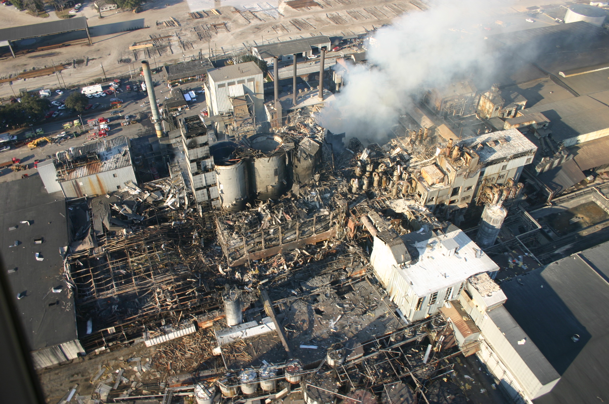
In an industrial setting, people will generally acknowledge that oil refineries and chemical plants are dangerous and can occasionally go boom in rather violent ways. More surprising is that something as seemingly innocuous as a sugar refinery and packing plant can go from a light sprinkling of sugar dust to a violent and lethal explosion within a second. This is however what happened in 2008 at the Georgia Imperial Sugar refinery, which killed fourteen and injured thirty-six. During this disaster, a primary and multiple secondary explosions ripped through the building, completely destroying it.
Georgia Imperial Sugar Refinery aftermath in 2008. (Credit: USCSB)
As described in the US Chemical Safety Board (USCSB) report with accompanying summary video (embedded below), the biggest cause was a lack of ventilation and cleaning that allowed for a build-up of sugar dust, with an ignition source, likely an overheated bearing, setting off the primary explosion. This explosion then found subsequent fuel to ignite elsewhere in the building, setting off a chain reaction.
What is striking is just how simple and straightforward both the build-up towards the disaster and the means to prevent it were. Even without knowing the exact air-fuel ratio for the fuel in question, there are only two points on the scale where you have a mixture that will not violently explode in the presence of an ignition source.
These are either a heavily saturated solution — too much fuel, not enough air — or the inverse. Essentially, if the dust-collection systems at the Imperial Sugar plant had been up to the task, and expanded to all relevant areas, the possibility of an ignition event would have likely been reduced to zero.
Things Like To Burn
In the context of dust explosions, it’s somewhat discomforting to realize just how many things around us are rather excellent sources of fuel. The aforementioned sugar, for example, is a carbohydrate (Cm(H2O)n). This chemical group also includes cellulose, which is a major part of wood dust, explaining why reducing dust levels in a woodworking shop is about much more than just keeping one’s lungs happy. Nobody wants their backyard woodworking shop to turn into a mini-Imperial Sugar ground zero, after all.
Carbohydrates aren’t far off from hydrocarbons, which includes our old friend petrol, as well as methane (CH4), butane (C4H10), etc., which are all delightfully combustible. All that the carbohydrates have in addition to carbon and hydrogen atoms are a lot of oxygen atoms, which is an interesting addition in the context of them being potential fuel sources. It incidentally also illustrates how important carbon is for life on this planet since its forms the literal backbone of its molecules.
Although one might conclude from this that only something which is a carbohydrate or hydrocarbon is highly flammable, there’s a whole other world out there of things that can burn. Case in point: metals.
Lit Metals
On December 9, 2010, workers were busy at the New Cumberland AL Solutions titanium plant in West Virginia, processing titanium powder. At this facility, scrap titanium and zirconium were milled and blended into a powder that got pressed into discs. Per the report, a malfunction inside one blender created a heat source that ignited the metal powder, killing three employees and injuring one contractor. As it turns out, no dust control methods were installed at the plant, allowing for uncontrolled dust build-up.
As pointed out in the USCSB report, both titanium and zirconium will readily ignite in particulate form, with zirconium capable of auto-igniting in air at room temperature. This is why the milling step at AL Solutions took place submerged in water. After ignition, titanium and zirconium require a Class D fire extinguisher, but it’s generally recommended to let large metal fires burn out by themselves. Using water on larger titanium fires can produce hydrogen, leading conceivably to even worse explosions.
The phenomenon of metal fires is probably best known from thermite. This is a mixture of a metal powder and a metal oxide. After ignited by an initial source of heat, the redox process becomes self-sustaining, providing the fuel, oxygen, and heat. While generally iron(III) oxide and aluminium are used, many more metals and metal oxides can be combined, including a copper oxide for a very rapid burn.
While thermite is intentionally kept as a powder, and often in some kind of container to create a molten phase that sustains itself, it shouldn’t be hard to imagine what happens if the metal is ground into a fine powder, distributed as a fine dust cloud in a confined room and exposed to an ignition source. At that point the differences between carbohydrates, hydrocarbons and metals become mostly academic to any survivors of the resulting inferno.
Preventing Dust Explosions
As should be quite obvious at this point, there’s no real way to fight a dust explosion, only to prevent it. Proper ventilation, preventing dust from building up and having active dust extraction in place where possible are about the most minimal precautions one should take. Complacency as happened at the Imperial Sugar plant merely invites disaster: if you can see the dust build-up on surfaces & dust in the air, you’re already at least at DEFCON 2.
A demonstration of how easy it is to create a solid dust explosion came from the Mythbusters back in 2008 when they tested the ‘sawdust cannon’ myth. This involved blowing sawdust into a cloud and igniting it with a flare, creating a massive fireball. After nearly getting their facial hair singed off with this roaring success, they then tried the same with non-dairy coffee creamer, which created an even more massive fireball.
Fortunately the Mythbusters build team was supervised by adults on the bomb range for these experiments, as it shows just how incredibly dangerous dust explosions can be. Even out in the open on a secure bomb range, never mind in an enclosed space, as hundreds have found out over the decades in the US alone. One only has to look at the USCSB’s dust explosions statistics to learn to respect the dangers a bit more.
It’s sometimes easy to forget that the light in the sky is an actual star. With how reliable it is and how busy we tend to be as humans, we can take that incredible fact and stow it away and largely go on with our lives unaffected. But our star is the thing that gives everything on the planet life and energy and is important to understand. Humans don’t have a full understanding of it either; there are several unsolved mysteries in physics which revolve around the sun, the most famous of which is the coronal heating problem. To help further our understanding a number of scientific instruments have been devised to probe deeper into it, and this adaptive optics system just captures some of the most impressive images of it yet.
Adaptive optics systems are installed in terrestrial telescopes to help mitigate the distortion of incoming light caused by Earth’s atmosphere. They generally involve using a reference source to measure these distortions, and then make changes to the way the telescope gathers light, in this case by making rapid, slight changes to the telescope’s mirror. This system has been installed on the Goode Solar Telescope in California and has allowed scientists to view various solar phenomena with unprecedented clarity.
The adaptive optics system here has allowed researchers to improve the resolution from the 1000 km resolution of other solar telescopes down to nearly the theoretical limit of this telescope—63 km. With this kind of resolution the researchers hope that this clarity will help shine some light on some of the sun’s ongoing mysteries. Adaptive optics systems like this aren’t just used on terrestrial telescopes, either. This demonstration shows how the adaptive optics system works on the James Webb Space Telescope.
Since the tail end of World War II, humanity has struggled to deal with its newfound ability to harness the tremendous energy in the nucleus of the atom. Of course there have been some positive developments like nuclear power which can produce tremendous amounts of electricity without the greenhouse gas emissions of fossil fuels. But largely humanity decided to build a tremendous nuclear weapons arsenal instead, which has not only cause general consternation worldwide but caused specific problems for one scientist in particular.
[Steve Weintz] takes us through the tale of [Dr. John C. Clark] who was working with the Atomic Energy Commission in the United States and found himself first at a misfire of a nuclear weapons test in the early 1950s. As the person in charge of the explosive device, it was his responsibility to safely disarm the weapon after it failed to detonate. He would find himself again in this position a year later when a second nuclear device sat on the test pad after the command to detonate it was given. Armed with only a hacksaw and some test equipment he was eventually able to disarm both devices safely.
One note for how treacherous this work actually was, outside of the obvious: although there were safety devices on the bombs to ensure the nuclear explosion would only occur under specific situations, there were also high explosives on the bomb that might have exploded even without triggering the nuclear explosion following it. Nuclear bombs and nuclear power plants aren’t the only things that the atomic age ushered in, though. There have been some other unique developments as well, like the nuclear gardens of the mid 1900s.