Vista de Lectura

Hay nuevos artículos disponibles. Pincha para refrescar la página.

Building a 3D Printed Scanning Tunneling Microscope
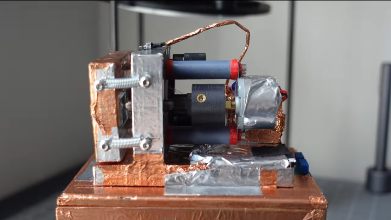
YouTuber [MechPanda] has recreated a DIY STM hack we covered about ten years ago, updating it to be primarily 3D-printed, using modern electronics, making it much more accessible to many folks. This simple STM setup utilises a piezoelectric actuator constructed by deliberately cutting a piezo speaker into four quadrants. With individual drive wires attached to the four quadrants. They (re)discovered that piezoelectric ceramic materials are not big fans of soldering heat. Still, in the absence of ultrasonic welding equipment, they did manage to get some wires to take to the surface using low-temperature solder paste.
As you can tell, you can only image conductive samples

They glued a makeshift probe holder on the rear side of the speaker actuator, which was intended to take a super sharp needle-like piece of tungsten wire. Putting the wire in tension and cutting at a sharp angle makes it possible with many attempts to get some usable points. Usable, in this instance, means sharp down the atomic level. The sample platform, actuator mount and all the connecting parts are 3D-printed with PA-CF. This is necessary to achieve enough mechanical stability with normal room temperature fluctuations. Three precision screws are used to level the two platforms in a typical kinematic mount structure, which looks like the only hard-to-source component. A geared stepper motor attached to the probe platform is set up to allow the probe to be carefully advanced towards the sample surface.
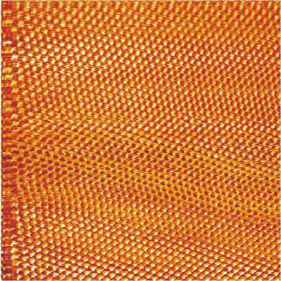
Graphite is not orange. This is a false-colour image!

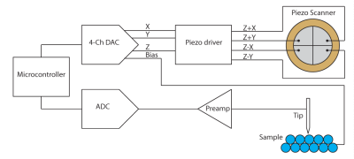
The next issue concerns vibration damping of the whole assembly. This was achieved with a simple hanging sprung platform, damped using an aluminium plate and magnets mounted underneath—a simple and effective eddy-current damper setup. For the electronics, a Teensy 4.1 runs the show, driving the four quadrants via a brace of AD5761 serial DACs and a few summing amplifiers. Three DACs generate the X, Y and Z signals, which are sent to the quadrants as Z+/-X and Z+/-Y, and the fourth DAC generates a sample bias signal. The tunnelling current picked up by the probe tip is first sent to a preamplifier constructed using a very high gain transconductance (current-to-voltage) amplifier. However, the part used was not identified. The whole assembly is electrically shielded with metallic tape, including the cable running down the main analog board, which hosts an LTC2326 ADC that can handle the bipolar differential signal being fed to it. The software was programmed using the Arduino stack for ease of use. The reason for the high-speed micro is the need to control the scanning signals based on the measured tunnelling current to form a control loop. We didn’t dig into precisely how that works! As can be seen from the video, they managed to get some quite decent images of the surface of a freshly peeled HOPG (graphite) lab specimen, so the setup works, and the noise sources are under control.

To read along, check out the project GitHub page, but more importantly, the original project by [Dan Berard.]

Thanks to [rolmie] for the tip!
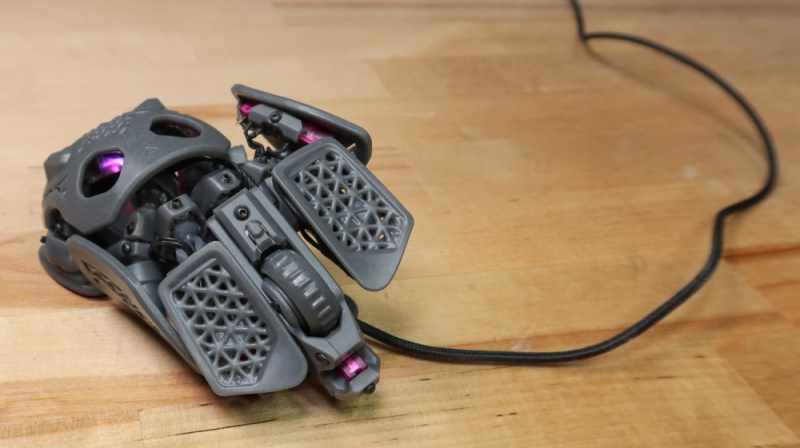
The Statial-b Open Source Adjustable Mouse

Many of us are very heavy computer users, and two items that can affect our comfort and, by extension, our health are the keyboard and the mouse. We’ve covered many ergonomic and customisable keyboards over the years, but we are not sure we’ve covered a fully adjustable mouse until now. Here’s [Charlie Pyott] with their second take on an adjustable mouse, the open source, statial-b.

[Charlie] goes into an extensive discussion of the design process in the video after the break, which is a fascinating glimpse into the methods used by a professional industrial designer. The statial concept breaks the contact surfaces of the mouse into fixed and moveable sections. The moveable sections are attached to the mouse core via a pair of ball joints connected with extendible arms, allowing the surfaces to be adjusted for both position and orientation. The design process starts with 3D scanning their ‘workhorse mouse,’ a Razer Deathadder Elite. This creates a reference volume within which the statial body should fit in its minimal configuration.

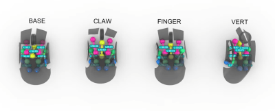
So which mouse grip style are you into?

The design has a fixed central core, with each button (including the central scroller) separately adjustable. The side panel with a pair of thumb buttons is also moveable. Creating a model in Rhino 3D working with the grasshopper visual programming environment [Charlies] explored the surface constraints for the base, claw, finger and vertical grip styles common among mouse users. This model was then fed into Fusion 360 for the detailed design. After completing the design, it was passed back into Rhino 3D to add lattice effects to the panel. This helps reduce weight and lets the internal LEDs shine through. The design is intended for resin printing, so you could go wild with the visuals by missing custom resins if you were so inclined.

For the electronics, [Charlie] based the design around an Arduino Pro Micro, taking input from a PWM3389 laser direction sensor module. These are soldered to a simple base PCB, which also houses PH series connectors for the moveable switches to hook into. Check out the GitHub project page for all the files and an excellent build guide! As mentioned earlier, we don’t see many custom mouse hacks, but here’s a nice DIY gaming mouse to look into. If desk space is tight, perhaps a DIY trackball is in order? And while thinking about input devices, what about a neat DIY PCB-coil 3D mouse?

Thanks to [Keith] for the tip!

Why have Seven Segments When You Can Have 21?

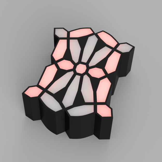
IO user [monte] was pointed towards an 1898 display patent issued to a [George Mason] and liked the look of the ‘creepy’ font it defined. The layout used no less than 21 discrete segments to display the complete roman alphabet and numerals, which is definitely not possible with the mere seven segments we are all familiar with. [monte] then did the decent thing and created a demonstration digit using modern parts.

For the implementation, [monte] created a simple PCB by hand (with an obvious mistake) and 3D-printed an enclosure and diffuser to match. After a little debugging, a better PCB was ordered from one of the usual overseas factories. There isn’t a schematic yet, but they mention using a CH32V003 Risc-V micro, which can be seen sitting on the rear of the PCB.

Maximum flexibility is ensured by storing every glyph as a 32-bit integer, with each LED corresponding to a single bit. It’s interesting to note the display incorporates serifs, which are definitely optional, although you could display sans-serif style glyphs if you wanted to. There is now a bit of a job to work out how to map character codes to glyph codes, but you can have a go at that yourself here. It’s still early doors on this project, but it has some real potential for a unique-looking display.

We love displays—every kind. Here’s a layout reminiscent of a VFD digit but done purely mechanically. And if you must limit yourself to seven digits, what about this unique thing?

3D Print Yourself These Mini Workshop Tools

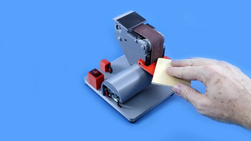
Kitting out a full workshop can be expensive, but if you’re only working on small things, it can also be overkill. Indeed, if your machining tends towards the miniature, consider building yourself a series of tiny machines like [KendinYap] did. In the video below, you can see the miniature electric sander, table saw, drill press, and cut-off saw put through their paces.

Just because the machines are small, doesn’t mean they’re not useful. In fact, they’re kind of great for doing smaller jobs without destroying what you’re working on. The tiny belt sander in particular appeals in this case, but the same applies to the drill press as well. [KendinYap] also shows off a tiny table and circular saw. The machines are straightforward in their design, relying largely on 3D printed components. They’re all powered by basic DC brushed motors which are enough to get the job done on the small scale.

They look particularly good if tiny scale model-making is your passion.

3D Printed RC Crane Has Epic 3-Foot Reach

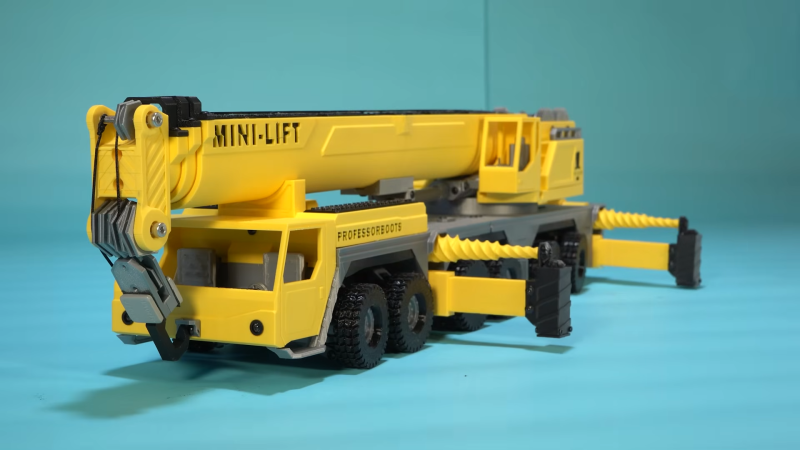
Have you ever looked out the window at traffic and seen a giant crane driving alone the road? Have you ever wanted a little 3D printed version you could drive for yourself without the risk of demolishing your neighbors house? Well, [ProfessorBoots] has just the build for you.

The build, inspired by the Liebherr LTM 1300, isn’t just a little RC car that looks like a crane. It’s a real working crane, too! So you can drive this thing around, and you can park it up. Then you can deploy the fully working stabilizer booms like you’re some big construction site hot shot. From there, you can relish in the subtle joy of extending the massive three-foot boom while the necessary counterweight automatically locks itself in place. You can then use the crane to lift and move small objects to your heart’s content.

The video describes how the build works in intimate detail, from the gears and linkages all the way up to the grander assembly. It’s no simple beast either, with ten gearmotors, four servos, and two ESP32s used for control. If you really need to build one for yourself, [ProfessorBoots] sells his plans on his website.

We’ve seen great stuff from [ProfessorBoots] before—he’s come a long way from his skid steer design last year. Video after the break.

Thanks to [Hudson Bazemore] for the tip!

Big Benchy Is a Boat That Really Boats

Benchy is that cute little boat that everyone uses to calibrate their 3D printer. [Emily The Engineer] asked the obvious question—why isn’t it a real working boat? Then she followed through on the execution. Bravo, [Emily]. Bravo.

The full concept is straightforward, but that doesn’t make it any less fun. [Emily] starts by trying to get small Benchys to float, and then steadily steps up the size, solving problems along the way. By the end of it, the big Benchy is printed out of lots of smaller sections that were then assembled into a larger whole. This was achieved with glue and simply using a soldering iron to melt parts together. It’s a common technique used to build giant parts on smaller 3D printers, and it works pretty well.

The basic hull did okay at first, save for some stability problems. Amazingly, though, it was remarkably well sealed against water ingress. It then got a trolling motor, survived a capsizing, and eventually took to the open water with the aid of some additional floatation.

We’ve seen big Benchys before, and we’ve seen fully functional 3D-printed boats before, too. It was about time the two concepts met in reality. Video after the break.

2024 Tiny Games Contest: Realistic Steering Wheel Joystick In Miniature

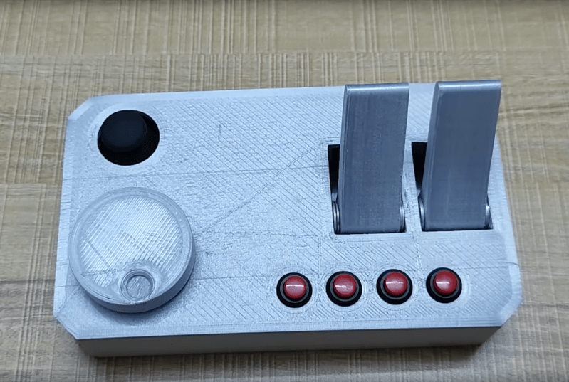
For racing games, flight simulators, and a few other simulation-style games, a simple controller just won’t do. You want something that looks and feels closer to the real thing. The major downsides to these more elaborate input methods is that they take up a large amount of space, requiring extra time for setup, and can be quite expensive as well. To solve both of these problems [Rahel zahir Ali] created a miniature steering wheel controller for some of his favorite games.

While there are some commercial offerings of small steering wheels integrated into an otherwise standard video game controller and a few 3D printed homebrew options, nothing really felt like a true substitute. The main design goal with this controller was to maintain the 900-degree rotation of a standard car steering wheel in a smaller size. It uses a 600P/R rotary encoder attached to a knob inside of a printed case, with two spring-loaded levers to act as a throttle and brake, as well as a standard joystick to adjust camera angle and four additional buttons. Everything is wired together with an Arduino Leonardo that sends the inputs along to the computer.

Now he’s ready to play some of his favorite games and includes some gameplay footage using this controller in the video linked below. If you’re racing vehicles other than cars and trucks, though, you might want a different type of controller for your games instead.

2024 Tiny Games Challenge

Using a 2D Scanner to Make 3D Things

[Chuck Hellebuyck] wanted to clone some model car raceway track and realised that by scanning the profile section of the track with a flatbed scanner and post-processing in Tinkercad, a useable cross-section model could be created. This was then extruded into 3D to make a pretty accurate-looking clone of the original part. Of course, using a flatbed paper scanner to create things other than images is nothing new, if you can remember to do it. A common example around here is scanning PCBs to capture mechanical details.

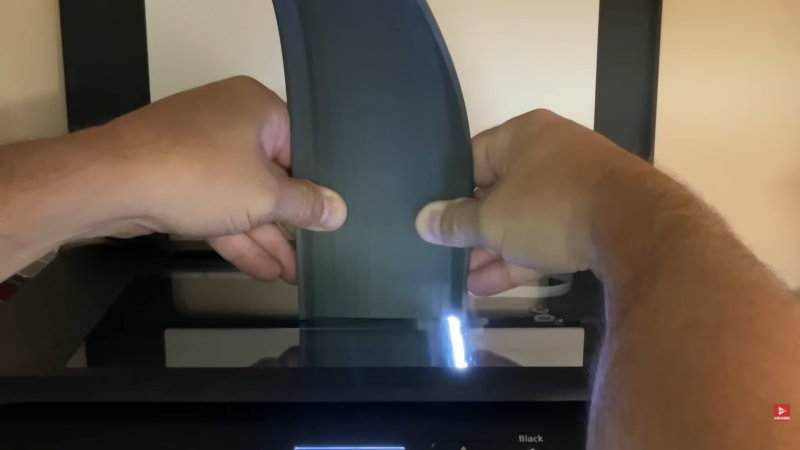
The goal was to construct a complex raceway for the grandkids, so he needed numerous pieces, some of which were curved and joined at different angles to allow the cars to race downhill. After printing a small test section using Ninjaflex, he found a way to join rigid track sections in curved areas. It was nice to see that modern 3D printers can handle printing tall, thin sections of this track vertically without making too much of a mess. This fun project demonstrates that you can easily combine 3D-printed custom parts with off-the-shelf items to achieve the desired result with minimal effort.

Flatbed scanner hacks are so plentiful it’s hard to choose a few! Here’s using a scanner to recreate a really sad-looking PCB, hacking a scanner to scan things way too big for it, and finally just using a scanner as a linear motion stage to create a UV exposure unit for DIY PCBs.

❌