Hackaday Links: November 17, 2024

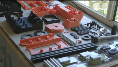
A couple of weeks back, we covered an interesting method for prototyping PCBs using a modified CNC mill to 3D print solder onto a blank FR4 substrate. The video showing this process generated a lot of interest and no fewer than 20 tips to the Hackaday tips line, which continued to come in dribs and drabs this week. In a world where low-cost, fast-turn PCB fabs exist, the amount of effort that went into this method makes little sense, and readers certainly made that known in the comments section. Given that the blokes who pulled this off are gearheads with no hobby electronics background, it kind of made their approach a little more understandable, but it still left a ton of practical questions about how they pulled it off. And now a new video from the aptly named Bad Obsession Motorsports attempts to explain what went on behind the scenes.
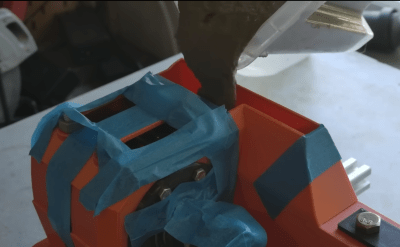
To be quite honest, although the amount of work they did to make these boards was impressive, especially the part where they got someone to create a custom roll of fluxless tin-silver solder, we have to admit to being a little let down by the explanation. The mechanical bits, where they temporarily modified the CNC mill with what amounts to a 3D printer extruder and hot end to melt and dispense the solder, wasn’t really the question we wanted answered. We were far more interested in the details of getting the solder traces to stick to the board as they were dispensed and how the board acted when components were soldered into the rivets used as vias. Sadly, those details were left unaddressed, so unless they decide to make yet another video, we suppose we’ll just have to learn to live with the mystery.
What do mushrooms have to do with data security? Until this week, we’d have thought the two were completely unrelated, but then we spotted this fantastic article on “Computers Are Bad” that spins the tale of Iron Mountain, which people in the USA might recognize as a large firm that offers all kinds of data security products, from document shredding to secure offsite storage and data backups. We always assumed the “Iron Mountain” thing was simply marketing, but the company did start in an abandoned iron mine in upstate New York, where during the early years of the Cold War, it was called “Iron Mountain Atomic Storage” and marketed document security to companies looking for business continuity in the face of atomic annihilation. As Cold War fears ebbed, the company gradually rebranded itself into the information management entity we know today. But what about the mushrooms? We won’t ruin the surprise, but suffice it to say that IT people aren’t the only ones that are fed shit and kept in the dark.
Do you like thick traces? We sure do, at least when it comes to high-current PCBs. We’ve seen a few boards with really impressive traces and even had a Hack Chat about the topic, so it was nice to see Mark Hughes’ article on design considerations for heavy copper boards. The conventional wisdom with high-current applications seems to be “the more copper, the better,” but Mark explains why that’s not always the case and how trace thickness and trace spacing both need to be considered for high-current applications. It’s pretty cool stuff that we hobbyists don’t usually have to deal with, but it’s good to see how it’s done.
We imagine that there aren’t too many people out there with fond memories of Visual Basic, but back when it first came out in the early 1990s, the idea that you could actually make a Windows PC do Windows things without having to learn anything more than what you already knew from high school computer class was pretty revolutionary. By all lights, it was an awful language, but it was enabling for many of us, so much so that some of us leveraged it into successful careers. Visual Basic 6 was pretty much the end of the line for the classic version of the language, before it got absorbed into the whole .NET thing. If you miss that 2008 feel, here’s a VB6 virtual machine to help you recapture the glory days.
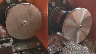
And finally, in this week’s “Factory Tour” segment we have a look inside a Japanese aluminum factory. The video mostly features extrusion, a process we’ve written about before, as well as casting. All of it is fascinating stuff, but what really got us was the glow of the molten aluminum, which we’d never really seen before. We’re used to the incandescent glow of molten iron or even brass and copper, but molten aluminum has always just looked like — well, liquid metal. We assumed that was thanks to its relatively low melting point, but apparently, you really need to get aluminum ripping hot for casting processes. Enjoy.


