Vista de Lectura

Hay nuevos artículos disponibles. Pincha para refrescar la página.

Disposable Vape Batteries Power eBike

There are a lot of things that get landfilled that have some marginal value, but generally if there’s not a huge amount of money to be made recycling things they won’t get recycled. It might not be surprising to most that this is true of almost all plastic, a substantial portion of glass, and even a lot of paper and metals, but what might come as a shock is that plenty of rechargeable lithium batteries are included in this list as well. It’s cheaper to build lithium batteries into one-time-use items like disposable vape pens and just throw them out after one (or less than one) charge cycle, but if you have some spare time these batteries are plenty useful.

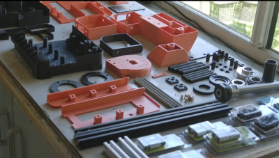
[Chris Doel] found over a hundred disposable vape pens after a local music festival and collected them all to build into a battery powerful enough for an ebike. Granted, this involves a lot of work disassembling each vape which is full of some fairly toxic compounds and which also generally tend to have some sensitive electronics, but once each pen was disassembled the real work of building a battery gets going. He starts with testing each cell and charging them to the same voltage, grouping cells with similar internal resistances. From there he assembles them into a 48V pack with a battery management system and custom 3D printed cell holders to accommodate the wide range of cell sizes. A 3D printed enclosure with charge/discharge ports, a power switch, and a status display round out the build.

With the battery bank completed he straps it to his existing ebike and hits the trails, easily traveling 20 miles with barely any pedal input. These cells are only rated for 300 charge-discharge cycles which is on par for plenty of similar 18650 cells, making this an impressive build for essentially free materials minus the costs of filament, a few parts, and the sweat equity that went into sourcing the cells. If you want to take an ebike to the next level of low-cost, we’d recommend pairing this battery with the drivetrain from the Spin Cycle.\

Thanks to [Anton] for the tip!
https://www.youtube.com/watch?v=VcVp9T8f_W4

Rapid Prototyping PCBs With The Circuit Graver

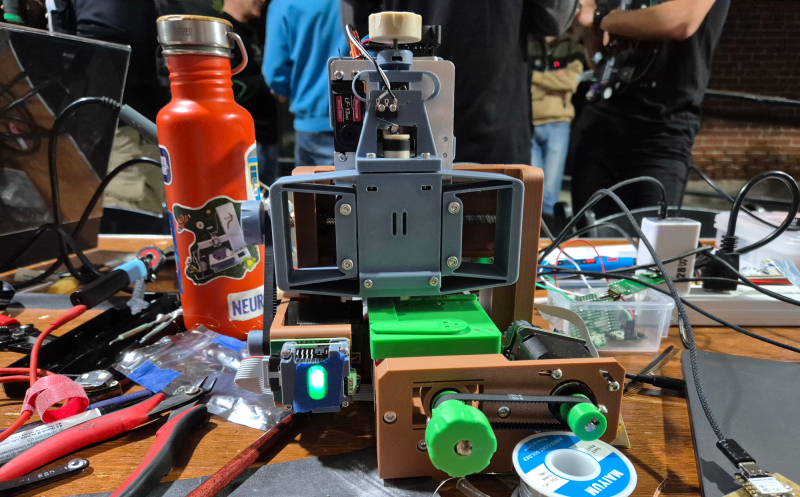
Walking around the alley at Hackaday Supercon 2024, we noticed an interesting project was getting quite a bit of attention, so we got nearer for a close-up. The ‘Circuit Graver’ by [Zach Fredin] is an unconventional PCB milling machine, utilizing many 3D printed parts, the familiar bed-slinger style Cartesian bot layout and a unique cutting head. The cutting tool, which started life as a tungsten carbide lathe tool, is held on a rotary (‘R’) axis but can also move vertically via a flexure-loaded carriage driven by a 13 kg servo motor.

The stocky flexure took a lot of iteration, as the build logs will show. Despite a wild goose chase attempting to measure the cutting force, a complete machine solution was found by simply making everything stiff enough to prevent the tool from chattering across the surface of the FR4 blank. Controlling and maintaining the rake angle was a critical parameter here. [Zach] actually took an additional step, which we likely wouldn’t have thought of, to have some copper blanks pre-fabricated to the required size and finished with an ENIG coating. It’s definitely a smart move!
To allow the production of PCB-class feature sizes compatible with a traditional PCB router, the cutting tool was sharpened to a much smaller point than would be used in a lathe using a stone. This reduced the point size sufficiently to allow feature sizes down to 4 mils, or at least that’s what initial characterization implied was viable.  As you can see from the build logs, [Zach] has achieved a repeatable enough process to allow building a simple circuit using an SMT 74HC595 and some 0402 LEDs to create an SAO for this year’s Supercon badge. Neat stuff!

We see a fair few PCB mills, some 3D printed, and some not. Here’s a nice one that fits in that former category. Milling PCBs is quite a good solution for the rapid prototyping of electronics. Here’s a guide about that.

Open-Source Robot Transforms

Besides Pokémon, there might have been no greater media franchise for a child of the 90s than the Transformers, mysterious robots fighting an intergalactic war but which can inexplicably change into various Earth-based object, like trucks and airplanes. It led to a number of toys which can also change shapes from fighting robots into various ordinary objects as well. And, perhaps in a way of life imitating art, plenty of real-life robots have features one might think were inspired by this franchise like this transforming quadruped robot.

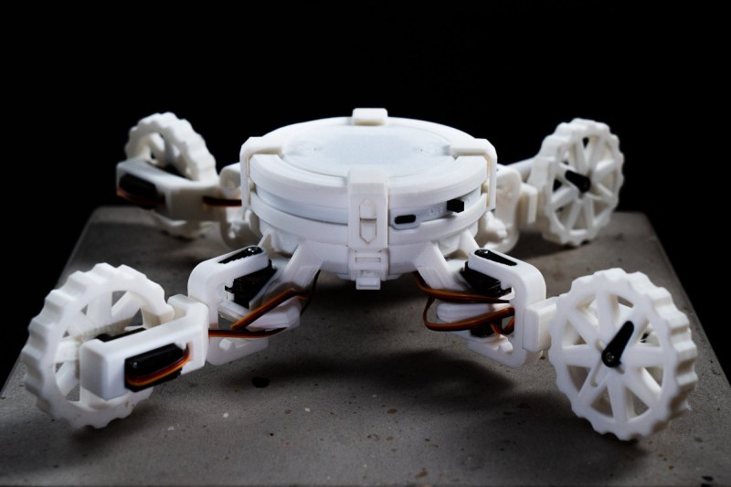
Called the CYOBot, the robot has four articulating arms with a wheel at the end of each. The arms can be placed in a wide array of positions for different operating characteristics, allowing the robot to move in an incredibly diverse way. It’s based on a previous version called the CYOCrawler, using similar articulating arms but with no wheels. The build centers around an ESP32-S3 microcontroller, giving it plenty of compute power for things like machine learning, as well as wireless capabilities for control or access to more computing power.

Both robots are open source and modular as well, allowing a range of people to use and add on to the platform. Another perk here is that most parts are common or 3d printed, making it a fairly low barrier to entry for a platform with so many different configurations and options for expansion and development. If you prefer robots without wheels, though, we’d always recommend looking at Strandbeests for inspiration.

Can You Homebrew A Running Shoe?

Unless you spend all your time lounging on the sofa, you probably own at least one pair of shoes. But have you ever thought to make your own to improve some aspect of your life? YouTube channel Answer in Progress set out to do precisely that, but it didn’t quite work out.

When you (well, other people) get into running, it’s tempting to believe a lot of the shoe company hype and just drop hundreds of dollars on the latest ‘super shoe’ and hope that will help you break your target time. But do you actually need to buy into all this, or can you make something yourself? The project aimed to get the 5k time down significantly, at any cost, but primarily by cheating with technology. The team set out to look at the design process, given that there is indeed a fair amount of science to shoe design. Firstly, after a quick run, the main issues with some existing shoes were identified, specifically that there are a lot of pain points; feet hurt from all the impacts, and knees take a real pounding, too. That meant they needed to increase the sole cushioning. They felt that too much energy was wasted with the shoes not promoting forward motion as much as possible; feet tended to bounce upwards so that a rocker sole shape would help. Finally, laces and other upper sole features cause distraction and some comfort issues, so those can be deleted.
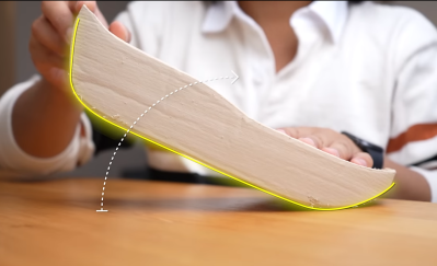
A thicker mid-sole allows for a rolled shape

The plan was to make a ‘sock’ shoe style, with an upper in one piece and stretchy enough to slip on without laces. The process started by wrapping the foot in cling film and then a few layers of duct tape to fix the shape. This was split down the top to extract the foot, open out the pattern, and transfer it to some nylon fabric. The outer profile was transferred and cut out with simple hand tools in a fashion that would allow the shape to be reconstructed as it was glued to a sole. It sounds simple, but it’s pretty fiddly work.

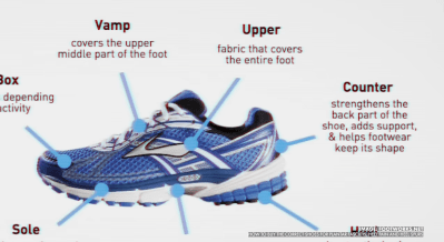
The latest running shoes use specialised rubber materials for the midsole. The solid foam wedge between the outer rubber and the inner sole cushions the foot. Those materials are only a few per cent ‘better’ than much more accessible foams that can be 3D printed. After sculpting a sole shape by hand using Blender, a friend 3D printed it. After that, the upper part was glued and ready for a test run. Which didn’t last long. It turned out that the lack of a stable heel counter (the bit around the back) that helps lock the heel in place meant the foot was too loose in the shoe, causing potential issues such as an ankle roll. That would be not good.  A follow-up session with a sports-focused chiropodist demonstrated that all this was rather pointless before the fundamental issues of strength and fitness were addressed. So, whilst it was fun to see an attempt to beat the big boys at their own game, it sure isn’t easy to pull it off, especially if you can’t get off the sofa.

The invention of flexible 3D printing filaments spurred the development of a wide range of 3D-printed footwear, like these low-poly beautiesWhile we’re 3D printing shoes, we also need some lace locks. Finally, with winter approaching for us Northerners, perhaps it’s time to run off a pair of 3D-printed strap-on cleats.

Thanks to [fluffy] for the tip!

A 3D Printed, Open Source Lathe?

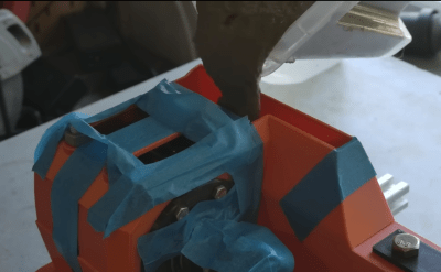
[Chris Borge] has spent the last few years creating some interesting 3D printed tools and recently has updated their 3D printable lathe design to make a few improvements. The idea was to 3D print the outer casing of the lathe in two parts, adding structural parts where needed to bolt on motors and tool holders, and then fill the whole thing with concrete for strength and rigidity.

Only a few parts to print

The printed base is initially held together with two lengths of studding, and a pile of bolts are passed through from below, mating with t-nuts on the top. 2020 extrusion is used for the motor mount. The headstock is held on with four thread rods inserted into coupling nuts in the base. The headstock unit is assembled separately, but similarly; 3D printed outer shell and long lengths of studding and bolts to hold it together. Decent-sized tapered roller bearings make an appearance, as some areas of a machine tool really cannot be skrimped. [Chris] explains that the headstock is separate because this part is most likely to fail, so it is removable, allowing it to be replaced.

Yes, that’s right. We’re filling it with lovely runny concrete.
Not a bad job on aluminium for a DIY lathe!

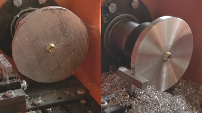
Once together, the whole assembly is filled with runny concrete and set aside to cure. Before fully curing, the top surfaces are scraped flat to remove excess concrete so the top covers will fit. A belt-driven motor is fitted, with associated control electronics, and then it’s time to talk tooling. The first tool shown is a simple T-shaped rest, used with a hand tool known as a ‘graver.’  This is more likely to be used on a wood lathe, but we reckon you could about get away with it if you’re really careful with aluminium or perhaps brass. An adjustable rest was made using a few simple pieces (in steel!) and held in a short length of 2020 extrusion in a manner that makes it adjustable, albeit not shown in this video. Finally, a reasonable torture test is demonstrated, comprising a rough-cut aluminium disk screwed to a threaded carrier. This was tidied up to make it nice and round and clean up its surfaces. The lathe survived, only melting the 3D printed motor pulley, which, as they say, should not have been a 3D printed part when metal parts are so easy to acquire! If you want to build one for yourself, then everything you need is here, but like with projects of this type, more development is still needed to overcome a few shortcomings. Check out [Chris]’s channel for many more interesting ideas!

We’ve seen a few of [Chris]’s other 3D-printed tools, like this neat fractal vice for odd-shaped objects. We like tiny tool hacks; after all, when you’re making small things, you don’t need full-sized tools.

Thanks to [CJay] for the tip!

Pac-Man Ghost Helps With Air Quality Sensing

In the past, building construction methods generally didn’t worry much about air quality. There were enough gaps around windows, doors, siding, and flooring that a house could naturally “breathe” and do a decent enough job of making sure the occupants didn’t suffocate. Modern buildings, on the other hand, are extremely concerned with efficiency and go to great lengths to ensure that no air leaks in or out. This can be a problem for occupants though and generally requires some sort of mechanical ventilation, but to be on the safe side and keep an eye on it a CO2 sensor like this unique Pac-Man-inspired monitor can be helpful.

Although there are some ways to approximate indoor air quality with inexpensive sensors, [Tobias] decided on a dedicated CO2 sensor for accuracy and effectiveness, despite its relatively large cost of around $30. An ESP32 handles the data from the sensor and then outputs the results to an array of LEDs hidden inside a ghost modeled after the ones from the classic arcade game Pac-Man. There are 17 WS2812B LEDs in total installed on a custom PCB, with everything held together in the custom 3D printed ghost-shaped case. The LEDs change from green to red as the air quality gets worse, although a few preserve the ghost’s white eyes even as the colors change.

For anyone looking to recreate this project and keep an eye on their own air quality, [Tobias] has made everything from the code, the PCB, and the 3D printer files open source, and has used accessible hardware in the build as well. Although the CO2 sensors can indeed be pricey, there are a few less expensive ways of keeping an eye on indoor air quality. Some of these methods attempt to approximate CO2 levels indirectly, but current consensus is that there’s no real substitute for taking this measurement directly if that’s the metric targeted for your own air quality.

❌