Vista de Lectura

Hay nuevos artículos disponibles. Pincha para refrescar la página.

Supercon 2024 SAO Petal KiCad Redrawing Project
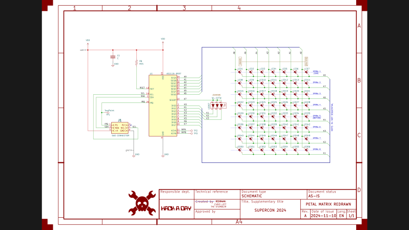
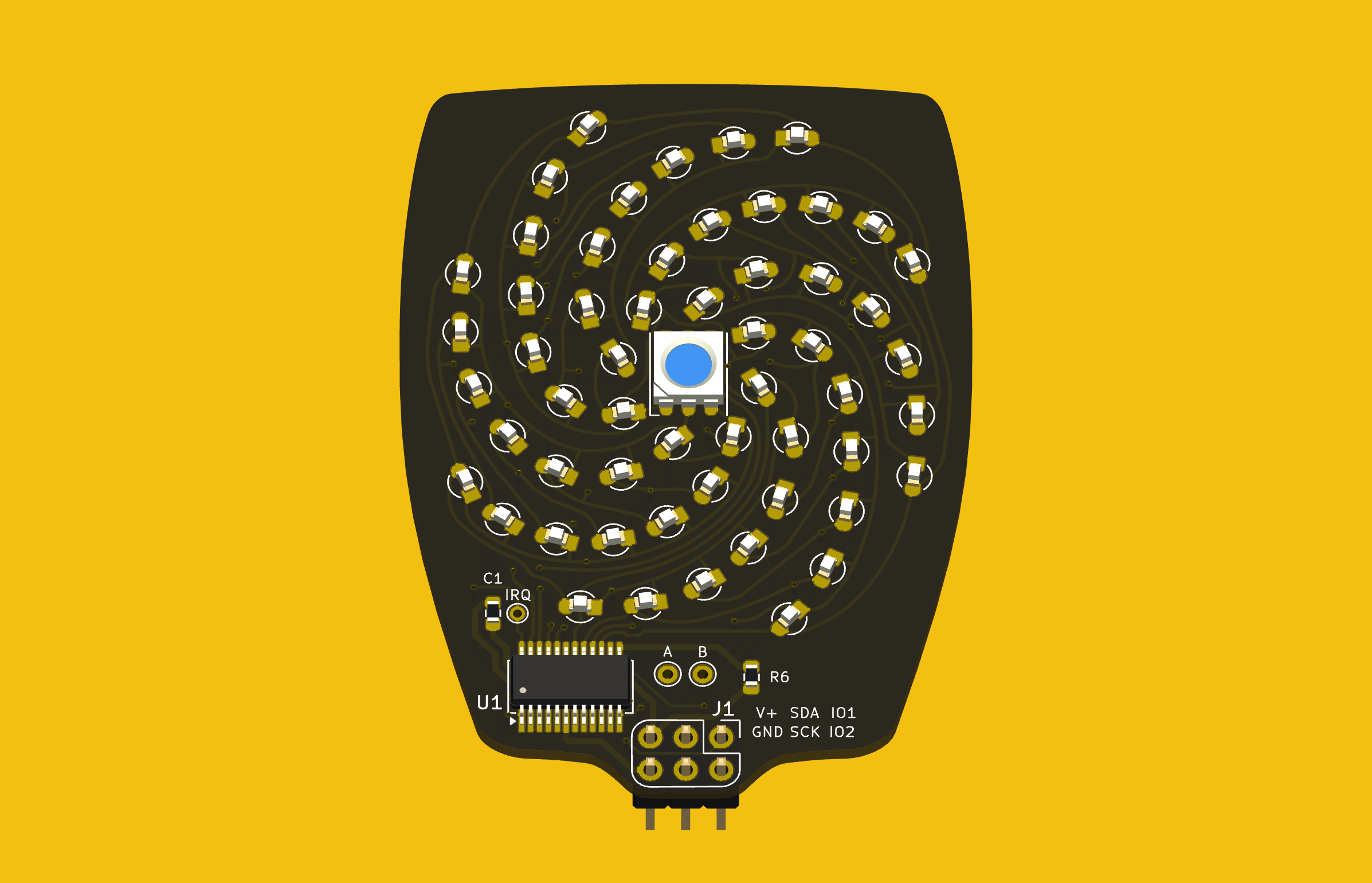
Last week I completed the SAO flower badge redrawing task, making a complete KiCad project. Most of the SAO petals are already released as KiCad projects, except for the Petal Matrix. The design features 56 LEDs arranged in eight spiral arms radiating from the center. What it does not feature are straight lines, right angles, nor parts placed on a regular grid.

Importing into KiCad
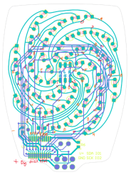
Circuit Notes for LEDs, Thanks to [spereinabox]
I followed the same procedures as the main flower badge with no major hiccups. This design didn’t have any released schematics, but backing out the circuits was straightforward. It also helped that user [sphereinabox] over on the Hackaday Discord server had rung out the LED matrix connections and gave me his notes.

Grep Those Positons

I first wanted to only read the data from the LEDs for analysis, and I didn’t need the full Kicad + Python scripting for that. Using grep on the PCB file, you get a text file that can be easily parsed to get the numbers. I confirmed that the LED placements were truly as irregular as they looked.

My biggest worry was how obtain and re-apply the positions and angles of the LEDs, given the irregular layout of the spiral arms. Just like the random angles of six SAO connector on the badge board, [Voja] doesn’t disappoint on this board, either. I fired up Python and used Matplotlib to get a visual perspective of the randomness of the placements, as one does. Due to the overall shape of the arms, there is a general trend to the numbers. But no obvious equation is discernable.

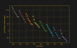
It was obvious that I needed a script of some sort to locate 56 new KiCad LED footprints onto the board. (Spoiler: I was wrong.) Theoretically I could have processed the PCB text file with bash or Python, creating a modified file. Since I only needed to change a few numbers, this wasn’t completely out of the question. But that is inelegant. It was time to get familiar with the KiCad + Python scripting capabilities. I dug in with gusto, but came away baffled.

KiCad’s Python Console to the Rescue — NOT

This being a one-time task for one specific PCB, writing a KiCad plugin didn’t seem appropriate. Instead, hacking around in the KiCad Python console looked like the way to go. But I didn’t work well for quick experimenting. You open the KiCad PCB console within the PCB editor. But when the console boots up, it doesn’t know anything about the currently loaded PCB. You need to import the Kicad Python interface library, and then open the PCB file. Also, the current state of the Python REPL and the command history are not maintained between restarts of KiCad. I don’t see any advantages of using the built-in Python console over just running a script in your usual Python environment.

Clearly there is a use case for this console. By all appearances, a lot of effort has gone into building up this capability. It appears to be full of features that must be valuable to some users and/or developers. Perhaps I should have stuck with it longer and figured it out.

KiCad Python Script Outside KiCad

This seemed like the perfect solution. The buzz in the community is that modern KiCad versions interface very well with Python. I’ve also been impressed with the improved KiCad project documentation on recent years. “This is going to be easy”, I thought.

First thing to note, the KiCad v8 interface library works only with Python 3.9. I run pyenv on my computers and already have 3.9 installed — check. However, you cannot just do a pip install kicad-something-or-other... to get the KiCad python interface library. These libraries come bundled within the KiCad distribution. Furthermore, they only work with a custom built version of Python 3.9 that is also included in the bundle. While I haven’t encountered this situation before, I figured out you can make pyenv point to a Python that has been installed outside of pyenv. But before I got that working, I made another discovery.

The Python API is not “officially” supported. KiCad has announced that the current Simplified Wrapper and Interface Generator-based Python interface bindings are slated to be deprecated. They are to be replaced by Inter-Process Communication-based bindings in Feb 2026. This tidbit of news coincided with learning of a similar 3rd party library.

Introducing KiUtils

Many people were asking questions about including external pip-installed modules from within the KiCad Python console. This confounded my search results, until I hit upon someone using the KiUtils package to solve the same problem I was having. Armed with this tool, I was up and running in no time. To be fair, I susepct KiUtils may also break when KiCad switched from SWIG to IPC interface, but KiUtils was so much easier to get up and running, I stuck with it.

I wrote a Python script to extract all the information I needed for the LEDs. The next step was to apply those values to the 56 new KiCad LED footprints to place each one in the correct position and orientation. As I searched for an example of writing a PCB file from KiUtils, I saw issue #113, “Broken as of KiCAD 8?”, on the KiUtils GitHub repository. Looks like KiUtils is already broken for v8 files. While I was able to read data from my v8 PCB file, it is reported that KiCad v8 cannot read files written by KiUtils.

Scripting Not Needed — DOH

At a dead end, I was about to hand place all the LEDs manually when I realized I could do it from inside KiCad. My excursions into KiCad and Python scripting were all for naught. The LED footprints had been imported from Altium Circuit Maker as one single footprint per LED (as opposed to some parts which convert as one footprint per pad). This single realization made the problem trivial. I just needed to update footprints from the library. While this did require a few attempts to get the cathode and anodes sorted out, it was basically solved with a single mouse click.

Those Freehand Traces

The imported traces on this PCB were harder to cleanup than those on the badge board. There were a lot of disconinuities in track segments. These artifacts would work fine if you made a real PCB, but because some segment endpoints don’t precisely line up, KiCad doesn’t know they belong to the same net. Here is how these were fixed:

  • Curved segments endpoints can’t be dragged like a straight line segment can. Solutions:
    • If the next track is a straight line, drag the line to connect to the curved segment.
    • If the next track is also a curve, manually route a very short track between the two endpoints.
  • If you route a track broadside into a curved track, it will usually not connect as far as KiCad is concerned. The solution is to break the curved track at the desired intersection, and those endpoints will accept a connection.
  • Some end segments were not connected to a pad. These were fixed by either dragging or routing a short trace.

Applying these rules over and over again, I finaly cleared all the discontinuities. Frustratingly, the algorithm to do this task already exists in a KiCad function: Tools -> Cleanup Graphics... -> Fix Discontinuities in Board Outline, and an accompanying tolerance field specified as a length in millimeters. But this operation, as noted in the its name, is restricted to lines on the Edge.Cuts layer.

PCB vs Picture
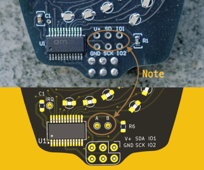
Detail of Test Pad Differences

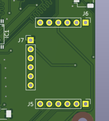
When I was all done, I noticed a detail in the photo of the Petal Matrix PCB assembly from the Hackaday reveal article. That board (sitting on a rock) has six debugging / expansion test points connected to the six pins of the SAO connector. But in the Altium Circuit Maker PCB design, there are only two pads, A and B. These connect to the two auxiliary input pins of the AS1115 chip. I don’t know which is correct. (Editor’s note: they were just there for debugging.) If you use this project to build one of these boards, edit it according to your needs.

Conclusion

The SAO Petal Matrix redrawn KiCad project can be found over at this GitHub repository. It isn’t easy to work backwards using KiCad from the PCB to the schematic. I certainly wouldn’t want to reverse engineer a 9U VME board this way. But for many smaller projects, it isn’t an unreasonable task, either. You can also use much simpler tools to get the job done. Earlier this year over on Hackaday.io, user [Skyhawkson] did a gread job backing out schematics from an Apollo-era PCB with Microsoft Paint 3D — a tool released in 2017 and just discontinued last week.
Bypassing Airpods Hearing Aid Georestriction With a Faraday Cage

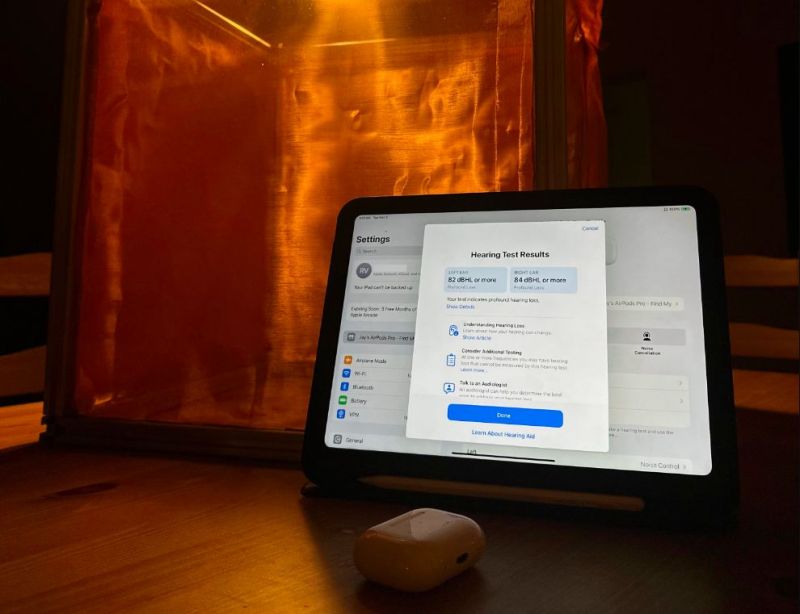
When Apple recently announced the hearing aid feature on their new AirPods Pro 2, it got the attention of quite a few people. Among these were [Rithwik Jayasimha] and friends, with [Rithwik] getting a pair together with his dad for use by his hard-of-hearing grandmother. That’s when he found out that this feature is effectively limited to the US and a small number of other countries due them being ‘regulated health features’, per Apple. With India not being on the approved countries list and with no interest in official approval legalities, [Rithwik] set to work to devise a way to bypass this restriction.

As noted in the blog post, the primary reason for using AirPods here instead of official hearing aids is due to the cost of the latter, which makes them a steal for anyone who is dealing with mild to moderate hearing loss. Following the official Hearing Aid feature setup instructions requires that your location is detected as being in an approved country. If it is, the Health App (on iOS 18.1) will popup a ‘Get Started’ screen. The challenge was thus to make the iOS device believe that it was actually in the FDA-blessed US and not India.

Merely spoofing the location and locale didn’t work, so the next step was to put the iOS device into a Faraday cage along with an ESP32 that broadcast California-based WiFi SSIDs. Once the thus treated iPad rebooted into the US, it could be used to enable the hearing aid feature. Next [Rithwik] and friends created a more streamlined setup and procedure to make it possible for others to replicate this feat.

As also noted in the blog post, the Hearing Aid feature is essentially a specially tuned Transparency mode preset, which is why using AirPods for this feature has been a thing for a while, but with this preset it’s much better tuned for cases of hearing loss.

Bluetooth Dongle Gives Up Its Secrets with Quick Snooping Hack

There’s a lot going on in our wireless world, and the number of packets whizzing back and forth between our devices is staggering. All this information can be a rich vein to mine for IoT hackers, but how do you zero in on the information that matters? That depends, of course, but if your application involves Bluetooth, you might be able to snoop in on the conversation relatively easily.

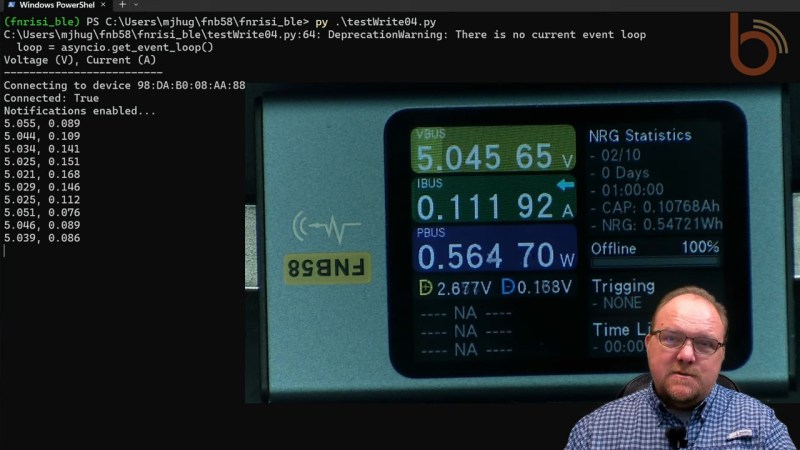
By way of explanation, we turn to [Mark Hughes] and his Boondock Echo, a device we’ve featured in these pages before. [Mark] needed to know how long the Echo would operate when powered by a battery bank, as well as specifics about the power draw over time. He had one of those Fnirsi USB power meter dongles, the kind that talks to a smartphone app over Bluetooth. To tap into the conversation, he enabled Host Control Interface logging on his phone and let the dongle and the app talk for a bit. The captured log file was then filtered through WireShark, leaving behind a list of all the Bluetooth packets to and from the dongle’s address.

That’s when the fun began. Using a little wetware pattern recognition, [Mark] was able to figure out the basic structure of each frame. Knowing the voltage range of USB power delivery helped him find the bytes representing voltage and current, which allowed him to throw together a Python program to talk to the dongle in real-time and get the critical numbers.

It’s not likely that all BLE-connected devices will be as amenable to reverse engineering as this dongle was, but this is still a great technique to keep in mind. We’ve got a couple of applications for this in mind already, in fact.

Help Wanted: Keep the World’s Oldest Windmills Turning

An image of a desert with dramatically cloudy skies. In the middle of the image is a series of clay doorways with vertically-oriented wooden slats surrounding a central pole. These form the basis of a panemone windmill.

While the Netherlands is the country most known for its windmills, they were originally invented by the Persians. More surprisingly, some of them are still turning after 1,000 years.

The ancient world holds many wonders of technology, and some are only now coming back to the surface like the Antikythera Mechanism. Milling grain with wind power probably started around the 8th Century in Persia, but in Nashtifan, Iran they’ve been keeping the mills running generation-to-generation for over 1000 years. [Mohammed Etebari], the last windmill keeper is in need of an apprentice to keep them running though.

In a world where vertical axis wind turbines seem like a new-fangled fad, it’s interesting to see these panemone windmills are actually the original recipe. The high winds of the region mean that the timber and clay structure of the asbad structure housing the turbine is sufficient for their task without all the fabric or man-made composites of more modern designs. While drag-type turbines aren’t particularly efficient, we do wonder how some of the lessons of repairability might be used to enhance the longevity of modern wind turbines. Getting even 100 years out of a turbine would be some wicked ROI.

Wooden towers aren’t just a thing of the past either, with new wooden wind turbines soaring 100 m into the sky. Since you’ll probably be wanting to generate electricity and not mill grain if you made your own, how does that work anyway?

Fail of the Week: Subscription EV Charger Becomes Standalone, Briefly

At this point in the tech dystopia cycle, it’s no surprise that the initial purchase price of a piece of technology is likely not the last payment you’ll make. Almost everything these days needs an ongoing subscription to do whatever you paid for it to do in the first place. It’s ridiculous, especially when all you want to do is charge your electric motorcycle with electricity you already pay for; why in the world would you need a subscription for that?

That was [Maarten]’s question when he picked up a used EVBox wall mount charger, which refused to charge his bike without signing up for a subscription. True, the subscription gave access to all kinds of gee-whiz features, none of which were necessary for the job of topping off the bike’s battery. A teardown revealed a well-built device with separate modules for mains supply and battery charging, plus a communications module with a cellular modem, obviously the bit that’s phoning home and keeping the charger from working without the subscription.

After some time going down dead ends and a futile search for documentation, [Maarten] decided to snoop into the conversation between the charger boards and the comms board, reasonably assuming that if he knew what they were talking about, he’d be able to mimic the commands that make the charger go. He managed to do exactly that, reverse engineering enough of the protocol to do a simple replay attack using a Raspberry Pi. That let him use the charger. Problem solved, right?

Not so fast — this is a “Fail of the Week,” after all. This is where [Maarten] should have called it a day, but he decided to keep poking enough to snatch defeat from the jaws of victory. He discovered that the charging module’s firmware was only doing limited validation of messages coming from the comms module, and since he’d only found fourteen of the commands in the protocol, he thought he’d take advantage of the firmware’s openness to explore all 256 possible commands. Scanning through all the commands proved fatal to the charger, though, bricking the poor thing right after he’d figured everything out. Ouch!

To his credit, [Maarten] was only trying to be complete in his exploration of the protocol, and his intention to make it easier for the next hacker is laudable in the extreme. That he took it a byte too far is unfortunate, but such is the price we sometimes pay for progress. Everything he did is thoroughly documented, so if you’ve got one of these chargers you’ve got all the tools needed to make it a standalone. Just make sure you know when to stop.

Tearing Down Nintendo’s Alarmo Alarm Clock

All your Nintendo Alarmo are belong to mew~ (Credit: GaryOderNichts, Blogspot)

Most of us will probably have seen Nintendo’s latest gadget pop up recently. Rather than a Switch 2 announcement, we got greeted with a Nintendo-branded alarm clock. Featuring a 2.8″ color LCD and a range of sensors, it can detect and respond to a user, and even work as an alarm clock for the low, low price of €99. All of which takes the form of Nintendo-themed characters alongside some mini-games. Naturally this has led people like [Gary] to buy one to see just how hackable these alarm clocks are.

As can be expected from a ‘smart’ alarm clock it has 2.4 GHz WiFi connectivity for firmware and content download, as well as a 24 GHz millimeter wave presence sensor. Before [Gary] even had received his Alarmo, others had already torn into their unit, uncovering the main MCU (STM32H730ZBI6) alongside a 4 GB eMMC IC, as well as the MCU’s SWD pads on the PCB. This gave [Gary] a quick start with reverse-engineering, though of course the MCU was protected (readout protection, or RDP) against firmware dumps, but the main firmware could be dumped from the eMMC without issues.

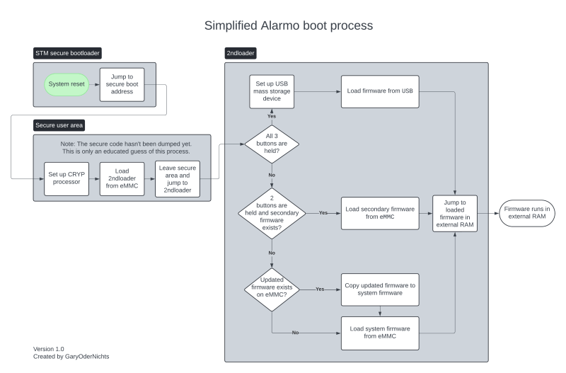
After this [Gary] had a heap of fun decrypting the firmware, which seems to always get loaded into the external octal SPI RAM before execution, as per the boot sequence (see featured image). This boot sequence offers a few possibilities for inserting one’s own (properly signed) contents. As it turns out via the USB route arbitrary firmware binaries can be loaded, which provided a backdoor to defeat RDP. Unfortunately the MCU is further locked down with Secure Access Mode, which prevents dumping the firmware again.

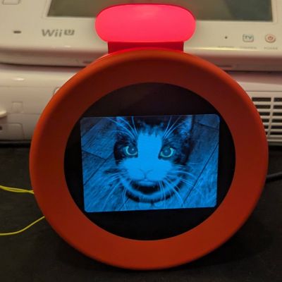
So far firmware updates for the Alarmo have not nailed shut the USB backdoor, making further reverse-engineering quite easy for the time being. If you too wish to hack your Alarmo and maybe add some feline charm, you can check [Gary]’s GitHub project.

How Pollution Controls for Cargo Ships Made Global Warming Worse

In 2020 international shipping saw itself faced with new fuel regulations for cargo ships pertaining to low sulfur fuels (IMO2020). This reduced the emission of sulfur dioxide aerosols from these ships across the globe by about 80% practically overnight and resulting in perhaps the biggest unintentional geoengineering event since last century.

As detailed in a recent paper by [Tianle Yuan] et al. as published in Nature, by removing these aerosols from the Earth’s atmosphere, it also removed their cooling effect. Effectively this change seems to have both demonstrated the effect of solar engineering, as well as sped up the greenhouse effect through radiative forcing of around 0.2 Watt/m2 of the global ocean.

The inadvertent effect of the pollution by these cargo ships appears to have been what is called marine cloud brightening (MCB), with the increased reflectivity of said clouds diminishing rapidly as these pollution controls came into effect. This was studied by the researchers using a combination of satellite observations and a chemical transport model, with the North Atlantic, the Caribbeans and South China Sea as the busiest shipping channels primarily affected.

Although the lesson one could draw from this is that we should put more ships on the oceans burning high-sulfur fuels, perhaps the better lesson is that MCB is a viable method to counteract global warming, assuming we can find a method to achieve it that doesn’t also increase acid rain and similar negative effects from pollution.

Featured image: Time series of global temperature anomaly since 1980. (Credit: Tianle Yuan et al., Nature Communications Earth Environment, 2024)

Hacker Tactic: Building Blocks

The software and hardware worlds have overlaps, and it’s worth looking over the fence to see if there’s anything you missed. You might’ve already noticed that we hackers use PCB modules and devboards in the same way that programmers might use libraries and frameworks. You’ll find way more parallels if you think about it.

Building blocks are about belonging to a community, being able to draw from it. Sometimes it’s a community of one, but you might just find that building blocks help you reach other people easily, touching upon common elements between projects that both you and some other hacker might be planning out. With every building block, you make your or someone else’s next project quicker, and maybe you make it possible.

Sometimes, however, building blocks are about being lazy.

Just Throw Pin Headers

Back when I was giving design review on a LVDS driver board for a Sony Vaio display, there was a snag – the display used, doesn’t generate its own backlight voltage, so you have to bring your own backlight driver. Well, I didn’t want to bother designing the backlight driver portion of the circuit.

The way I justified it, adding that circuit to the board didn’t make much sense – the entire board was an experimental circuit, and adding one more experiment onto it would result in extra board revisions and reassemblies. Honestly, though, I just really didn’t want to design the LED driver circuit at the time – it didn’t feel as interesting.
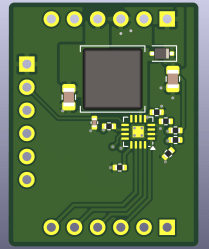
So, I had an easy-to-follow proposal – let’s put all backlight-driver-related signals onto three pin headers, forming a “module” footprint of sorts, and then develop the module separately! The hacker agreed, and in the meantime, used a spare panel’s LED backlight to test the display in the meantime – way more accessible of a solution. The pin headers remained, at the time, bound to be unpopulated for, at least, until the next PCB order.

New revisions of the module came and went, now bearing a HDMI port and a whole new ASIC – easy to design, because, again, the hacker didn’t have to worry about the backlight circuit, and just kept the module footprint from the previous design. Was the backlight driver module PCB designed yet? Well, simply put, no.

A friend of mine, just a month later, was designing a motherboard replacement for a tablet computer, and she asked me for advice on how to power the backlight. I thought for a second, and, I had an easy answer for her – use the module footprint. At that point, I still haven’t designed the module, but I didn’t have to mention that. She rejoiced, put the module footprint onto the board, even designed her own neat symbol for it, and then promptly went on to lay out diffpairs and reverse-engineer pinouts, both significantly more fun activities than designing a backlight driver with zero experience in design of backlight drivers.
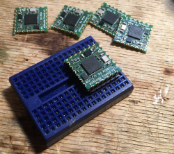
Some time later, I started getting insistent messages from the original hacker, about needing a backlight driver. The funny part is that by that point, I have already had designed a backlight driver circuit for my own Vaio motherboard, but I never felt engaged enough to turn it into a module. A different friend of mine was looking for small projects, however. I gave her the task: here’s a footprint for a module, here’s a circuit that goes onto the module, and we need a module. Indeed, she has delivered a module – by that point, a module we could put onto three different PCBs.

Building Blocks

The entire occasion definitely helped cement my reputation as someone who delivers, eventually – with big emphasis on eventually. It also brought four people and three projects together, and it let us order the first revision PCB way sooner than otherwise, all because we set out to eventually add the backlight circuit as a module. Now, this module is a building block in our projects – whenever one of us, or maybe one of you, needs a backlight driver, we know that we have an option handy.

I have some unique experiences with PCB modules as building blocks – at one point, I’ve built an entire phone out of them, and I still build devices heavily based on modules. Whenever I’d have the occasion, I’d throw a TP4056 module footprint onto a board instead of reimplementing the whole circuit from scratch. In 2022, I designed a module with a RP2040 and the FUSB302 USB-PD PHY – it was the building block that led to my USB-C series on Hackaday, and eventually helped me, my friends, and other hackers develop a whole lineup of unique USB-C devices.

Building block use and design is the fun way, and it’s the lazy way, and it’s the friendly way – would you believe me if I told you it’s also the safe way? Say, does your circuit need a custom DC-DC, or can you slap a few pads onto the board to connect a commonplace generic module? If you can afford the increased space, might as well make your board as simple as it goes – if there’s less to test and bringup, you’ll get to your project’s finish line earlier, and have less hurdles to jump over.

The Practical Aspects

There are a few techniques you can use if you want to make a building block – pin headers are the simple obvious one. Castellations is a fun one, and here’s a trick – you don’t have to pay JLCPCB for castellated holes, as long as you are fine getting dirty ones, which are still wonderful for prototyping. If you’re using Aisler, you can get perfect castellated holes, though – good for scaling up a module of yours after you’ve verified the design. Don’t be scared of turning through-holes into castellations – it works, and it’s super easy if your board is thin enough. Oh, and you might just be able to get castellations through V-Cuts!

this module is a mainstay on my 18650 helper boards I’ve covered here

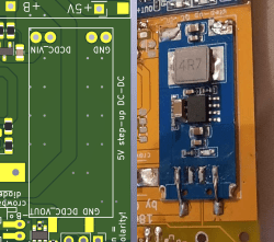
Got an Eastern or Western module, and it doesn’t quite use pin headers? Get out the calipers, measure its pads, and create a footprint for it – you will thank yourself later. I’ve done just once for a 5 V boost module, stocking up on them and putting them onto a bunch of boards. It’s not like I’d feel comfortable designing 5 V boost regulators at the time, so the module has bought me a couple years of worrying about something else instead. The modules have since vanished from the market, but, today I’ve got a few 5 V boost designs I can easily make modules out of. Now, it looks like I can even upgrade my own old boards that are still in use!

When designing your own boards, try to put all pin headers on a grid, 2.54 mm (0.1in) is a must – only use an integer millimeter grid or pin headers if you have no other options. Such a module isn’t just solderable – it’s breadboardable, which helps a ton when you’re trying to figure out an especially daring circuit technique. Castellated modules can be breadboardable, too, if you make sure to concentrate the core necessary signals on two opposite sides!

Are you designing a new module for your own use? See if there’s a footprint you can copy, or an unspoken standard you can follow. Boards speak about themselves through their looks, and footprints convey a purpose through their layout. Look at the boards above- it’s pretty easy to notice that they are TP4056 style battery chargers, but all of them upgraded in their own way. If you follow an existing footprint when designing your own board, it’s going to look more familiar for a newcomer hacker, channeling the power of skeuomorphism where you might not have expected to find it.

The Looks Make The Module

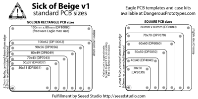
Looking for a PCB form-factor? Going with a Dangerous Prototypes-blessed one brings you a ton of benefits, e.g., pre-made lasercut cases.

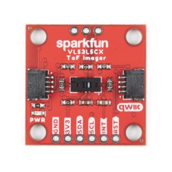
Board formats are underrated when it comes to accidentally creating building blocks. Sparkfun has example layouts for QWIIC devices – follow it, plop a JST-SH connector on, maybe order your PCB in red for a change, and your sensor PCB will shine in a whole new way in your eyes. Dangerous Prototypes, on the other hand, suggests a set of PCB formats known as Sick of Beige that work with existing enclosures and lasercut templates – that’s the surface-level benefit, the real deal is that these footprints also talk the Dangerous Prototypes language. If your programmer board feels like a generic rectangle, putting it into the frame of BusPirate fame will give it the air of hacker-oriented tooling. With both of these formats, you get mounting holes – mark of a hacker who knows what’s good.

Looking for a ToF sensor? Looking at this picture, you can instantly tell that this one‘s I2C and 3.3V – chances are, it will fit wonderfully into your project.

Interconnect standards go hand in hand with making your building blocks’ features recognizable without reading the silkscreen – it’s why I talk so much about QWIIC, and a JST-SH connector is always a welcome addition on my boards. Adding a well-recognized standard connector makes your board recognizable as a potential building block. Now, the board looks interoperable if you just give it a chance, equipped with a familiar socket, and perhaps, you won’t feel as much need for designing a new one – quite likely, building a new device in a single day instead of two weeks’ time.

Sometimes, your board will be split apart into building blocks without your involvement whatsoever. Publishing a design that goes beyond connecting a button to an LED? Try to fill in the blanks – it’s about helping the hacker that follows in your footsteps. Sometimes it’s a highschool kid trying to put together a design, and sometimes it’ll be you again, just a couple years later. So, note down the part number of that switcher inductor in the schematic, and fill in the values of the resistor divider while you’re at it – and if you’re revisiting a board of yours where you haven’t done that, do it, then git commit and git push.

Beyond The Ordinary

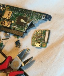
In a pinch, rip and tear until it’s done

There’s building blocks everywhere for those with the eyes to see. A single-board computer is one, I’d argue – a SoM in a DDR footprint is one without a doubt. An engineer once showed me a technique for creating building blocks out of thin air – taking unpopulated leftover large project PCBs, then sawing out the section with the circuit you need. Sometimes, you really only need a single piece of that one Ethernet transceiver circuit, and you need it now – you might have not planned for it, but the Dremel tool forgives all.

Circuit blocks are an often requested feature in KiCad. At the moment, you can copy-paste portions of a schematic between projects – which is more than good enough for many circuits. It’s not as great for switching regulators or MCUs, however, and we can’t help but hope to see new advancements in the field soon. Perhaps, one day, you’ll be able to click a few buttons and turn your favourite USB hub into a circuit block – and from there, who knows, maybe you can fill the void that the NanoHub’s eternal out-of-stock state has left in our hearts!

❌