Vista de Lectura

Hay nuevos artículos disponibles. Pincha para refrescar la página.

Crowdsourcing Ionosphere Data with Phones

How do you collect a lot of data about the ionosphere? Well, you could use sounding rockets or specialized gear. Or maybe you can just conscript a huge number of cell phones. That was the approach taken by Google researchers in a recent paper in Nature.

The idea is that GPS and similar navigation satellites measure transit time of the satellite signal, but the ionosphere alters the propagation of those signals. In fact, this effect is one of the major sources of error in GPS navigation. Most receivers have an 8-parameter model of the ionosphere that reduces that error by about 50%.

However, by measuring the difference in time between signals of different frequencies, the phone can estimate the total electron current (TEC) of the ionosphere between the receiver and the satellite. This requires a dual-frequency receiver, of course.

This isn’t a new idea. There are a large number of fixed-position stations that make this measurement to contribute to a worldwide database. However, the roughly 9,000 stations can’t compete with cell phones everywhere. The paper outlines how Android smartphones can do calculations on the GPS propagation delays to report the TEC numbers.

Hams often study the ionosphere. So do sounding rockets.
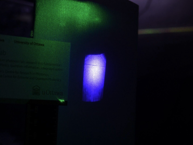
The Laser Shadow Knows

Normally, you think of things casting a shadow as being opaque. However, new research shows that under certain conditions, a laser beam can cast a shadow. This may sound like nothing more than a novelty, but it may have applications in using one laser beam to control another. If you want more details, you can read the actual paper online.

Typically, light passes through light without having an effect. But using a ruby crystal and specific laser wavelengths. In particular, a green laser has a non-linear response in the crystal that causes a shadow in  a blue laser passing through the same crystal.

The green laser increases the crystal’s ability to absorb the blue laser beam. which creates a matching region in the blue beam that appears as a shadow.

If you read the article, there’s more to measuring shadows than you might think. We aren’t sure what we would do with this information, but if you figure it out, let us know.

Ruby has a long history with lasers, of course. That green laser pointer you have? It might not be all green, after all.

Analog Shift Register Revealed

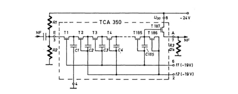
Nowadays, if you want to delay an audio signal for, say, an echo or a reverb, you’d probably just do it digitally. But it wasn’t long ago that wasn’t a realistic option. Some devices used mechanical means, but there were also ICs like the TCA350 “bucket brigade” device that [10maurycy10] shows us in a recent post.

In this case, bucket brigade is a euphemism calling to mind how firemen would pass buckets down the line to put out a fire. It’s a bit of an analog analogy. The “bucket” is a MOSFET and capacitor. The “water” is electrical charge stored in the cap.  All those charges are tiny snippets of an analog signal.

In practice, the chip has two clock signals that do not overlap. The first one gates the signal to a small capacitor which follows the input signal voltage. Then, when that gate clock closes, the second clock gates that output to another identical capacitor. The second capacitor discharges the first one and the whole process repeats, sometimes for hundreds of times.

In addition to a test circuit and some signals going in and out, the post also shows photomicrographs of the chip’s insides. As you might expect, all those identical gates make for a very regular layout on the die.

You might think these devices are obsolete, and that’s true. However, the basic idea is still in use for CCD camera sensors.

Sometimes, those old delay lines were actually columns of mercury or coiled-up transmission lines. You could even use a garden hose or build your own delay line memory.

Open Source Universal ROM Programmer Grows Up

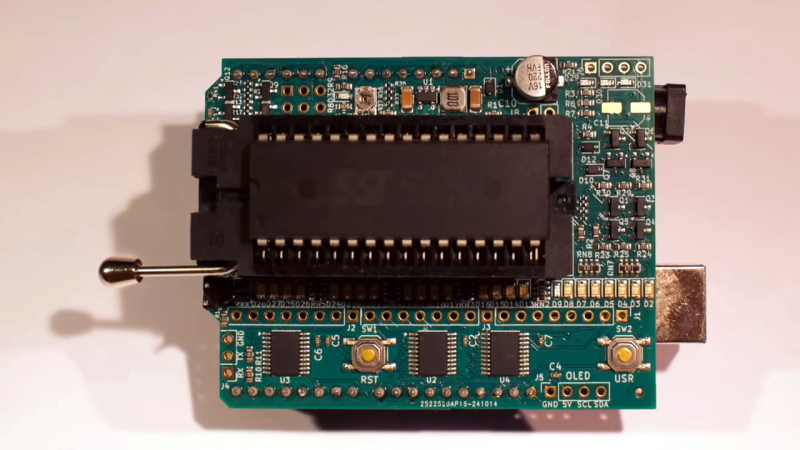
When we first looked at [Anders Nielsen’s] EEPROM programmer project, it was nice but needed some software and manual intervention and had some limitations on the parts you could program. But through the magic of Open-Source collaboration, revision 2 of the project overcomes all of these limitations and—as you can see in the video below—looks very polished.

If you recall, the programmer is in a “shield” format that can plug into an Arduino or — if you prefer a retrocomputer — a 6502uno. Along with hardware improvements from the community, [Henrik Olsson] wrote Python software to handle the programming (see the second video below).

The biggest change in the new version is that you don’t have to configure the voltages with jumpers anymore. This was required because different devices draw power on different pins, but a clever two-transistor circuit lets the software handle it. There is still one jumper for switching between 32-pin and 28-pin EEPROMs. The extra transistors added four cents to the total price, although if you buy the kit from [Anders], it is still $9, just like before.

Skimming the database, we don’t see any Microcontrollers (MPUs). However, it looks like the device should be able to program flash MPUs, too.

We covered the first edition of this project, and we were impressed even then. We do hope people will add MPUs and other devices like PALs to the project over time.

It’s a Soldering Iron! It’s A Multimeter! Relax! It’s Both!

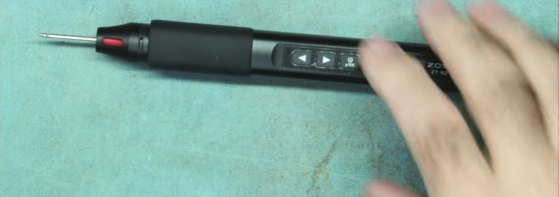
Imagine this. A young person comes to you wanting to get started in the electronic hobby. They ask what five things should they buy to get started. Make your list. We’ll wait. We bet we can guess at least two of your items: a multimeter, and a soldering iron. [LearnElectroncsRepair] recently showed us a review of the Zotek Zoyi ZT-N2 which is a soldering iron and a multimeter in one unit. You can watch the video review below.

Honestly, when we heard about this, we didn’t think much of the combination. It doesn’t seem like having your probe get red hot is a feature. However, the probe tip replaces the soldering iron tip, so you are either soldering or measuring, but not both at the same time.

The soldering iron part looks a lot like a T100 iron with a USB connector and a little LCD screen. The device is portable, so it has a little cheap soldering iron stand. As a multimeter, it does all the basic tests, but it is only usable for low-voltage applications under 36V.

The negative lead plugs into the USB connector, so the meter runs off an internal battery. While it looks like it is usable, we couldn’t really think of many cases where this would be handy unless you are really trying to pack a lot in a small space. We’d rather throw a small meter in the bag and call it a day.

In 2017, these little soldering irons were a fresh fad. Now, they are pretty common.

RISC-V Pushes 400 Million Forth Words Per Second

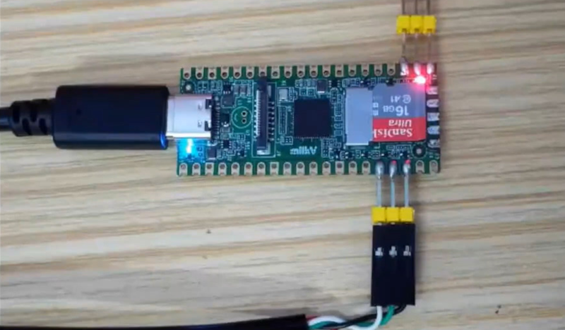
We’ll be honest. Measuring Forth words per second doesn’t seem like a great benchmark since a Forth word could be very simple or quite complex. But we think the real meaning is “up to 400 million words per second.” There was a time when that level of performance would take a huge computer. These days, a simple board that costs a few bucks can do the trick, according to [Peter Forth] in an online presentation.

The key is the use of the Milk V Duo and some similar boards. Some of these look similar to a Raspberry Pi Pico. However, this chip on board has two RISC V cores, an ARM core, and an 8051. There’s also an accelerator coprocessor for vector operations like AI or video applications.

[Peter] has some popular Forth systems ported to the machine on GitHub. This might be the easiest way to get started because, as he mentions in the video, the documentation for these boards leaves something to be desired. However, these chips have a lot of capability for a small price.

We like Forth. If you want something that is less of a port, we’ve seen some native RISC V implementations.

Building a Reproduction Apple I

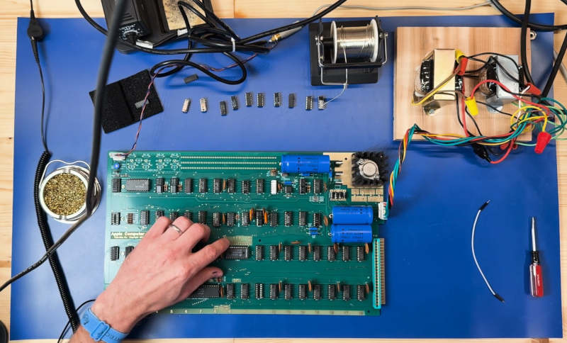
If you think of Apple today, you probably think of an iPhone or a Mac. But the original Apple I was a simple PC board and required a little effort to start up a working system. [Artem] has an Apple I reproduction PCB, and decided to build it on camera so we could watch.

For the Apple I, the user supplied a keyboard and some transformers, so [Artem] had to search for suitable components. He wisely checks the PCB to make sure there are no shorts in the traces. From there, you can watch him build the machine, but be warned: even with speed ups and editing, the video is over an hour long.

If you want to jump to the mostly working device, try around the 57-minute mark. The machine has a basic ROM monitor and, of course, needs a monitor. There was a small problem with memory, but he eventually worked it out by inhibiting some extra RAM on the board. Troubleshooting is half of the battle getting something like this.

Want to look inside the clock generator chip? Or skip the PCB and just use an FPGA.

Intuition about Maxwell’s Equations

You don’t have to know how a car engine works to drive a car — but you can bet all the drivers in the Indy 500 have a better than average understanding of what’s going on under the hood. All of our understanding of electronics hinges on Maxwell’s equations, but not many people know them. Even fewer have an intuitive feel for the equations, and [Ali] wants to help you with that. Of course, Maxwell’s gets into some hairy math, but [Ali] covers each law in a very pragmatic way, as you can see in the video below.

While the video explains the math simply, you’ll get more out of it if you understand vectors and derivatives. But even if you don’t, the explanations provide a lot of practical understanding

Understanding the divergence and curl operators is one key to Maxwell’s equations. While this video does give a quick explanation, [3Blue1Brown] has a very detailed video on just that topic. It also touches on Maxwell’s equations if you want some reinforcement and pretty graphics.

Maxwell’s equations can be very artistic. This is one of those topics where math, science, art, and history all blend together.

Teaching Computers to Read — Sort Of

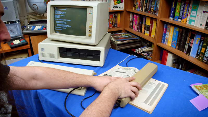
If you ask someone who grew up in the late 1970s or early 1980s what taught them a lot about programming, they’d probably tell you that typing in programs from magazines was very instructive. However, it was also very boring and error-prone. In fact, we’d say it was less instructional to do the typing than it was to do the debugging required to find all your mistakes. Magazines hated that and, as [Tech Tangents] shows us in a recent video, there were efforts to make devices that could scan barcodes from magazines or books to save readers from typing in the latest Star Trek game or Tiny Basic compiler.

The Cauzin Softstrip was a simple scanner that could read barcodes from a magazine or your printer if you wanted to do backups. As [Tech Tangents] points out, you may not have heard of it, but at the time, it seemed to be the future of software distribution.

We were impressed that [Tech Tangent] had enough old magazines that he had some of the original strips. Byte Magazine had tried to promote a similar format, but there was no hardware made to read those barcodes.

Of course, there were other systems. For example, the HP-41C famously had a barcode scanner, although creating your own was clunky unless you reverse-engineered the “proper” format (which was done). The basic hardware used there also worked with Byte’s format, but you still had to interface the odd scanner to your computer.

Cauzin sidestepped all this with their product, which was simple-to-interface hardware with software support for the major platforms. However, by the time it was on the market, cheap magnetic media and modem-based bulletin boards were destroying interest in loading software from paper.

This is a great look at an almost forgotten technology. You could probably build something modern to scan these if you had the urge. These days, it would be easy enough to design your own system. Modern laser printers would probably make very dense barcodes.

We wouldn’t suggest making a Cauzin guitar, though. These days we have QR codes and even colorful barcodes.

Z80 Testing the 80s Way

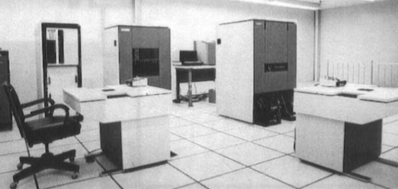
According to [MTSI], if you used a Z80 chip back in the 1980s, it almost certainly passed through the sole Fairchild Sentry 610 system that gave it the seal of approval.

The Sentry was big iron for its day. The CPU was a 24-bit device and ran at a blistering 250 kHz. Along with a tape drive and a specialized test bed, it could test Z80s, F8s, and other Mostek products of the day. There was a disk drive, too. The 26-inch platters stored under 10 kilobytes. Despite the relatively low speed of the CPU, the Sentry could test devices running up to 10 MHz, which was plenty for the CPUs it was testing. The actual test interface ran at 11 MHz and used an exotic divider to generate slower frequencies.

According to the post, an informal count of the number of chips in the device came up with around 60,000. That, as you might expect, took a huge power supply, too.

From some 1975 corporate literature:

“Optimized for engineering, sophisticated production needs, QA and test center operations, the Sentry 610 is the most versatile analytical tester available for engineering and production. It can perform the widest range of tests for the broadest range of components. At user option, the Sentry 610 can perform high-speed MaS/LSI, PCB, and bipolar tests simultaneously. It offers complete testing at the wafer level and through automatic handlers at full-rated device speeds up to 10 MHz. The wide choice of peripherals gives the Sentry 610 system massive data handling capacity to manipulate, analyze, compute and generate reports on test procedures in analyzing MaS/LSI.”

These days, you are as likely to stick test hardware on the IC as have a big machine on the outside. And even then, you probably wouldn’t have something this elaborate. But in its day, this was high-tech for sure.

The Z80 sure has had a long lifespan. It shouldn’t surprise you that Z80s need to be tested, just like everything else.

Cheap Sensor Changes Personality

If you want to add humidity and temperature sensors to your home automation sensor, you can — like [Maker’s Fun Duck] did — buy some generic ones for about a buck. For a dollar, you get a little square LCD with sensors and a button. You even get the battery. Can you reprogram the firmware to bend it to your will? As [Duck] shows in the video, you can.

The device advertises some custom BLE services, but [Duck] didn’t want to use the vendor’s phone app, so he cracked the case open. Inside was a microcontroller with Bluetooth, an LCD driver, a sensor IC, and very little else.

The processor is an ARM Cortex M0, a PHY6222 with very low power consumption. The LCD is a very cheap panel with no drivers onboard. All the drive electronics are on the PCB. The sensor is a CHT8305C which uses I2C.

Luckily, the PHY6222 has a publically available SDK with English documentation. The PCB has two sets of UART pads and it is possible to flash the chip via one of the UARTs.

Eventually, [Duck] put a custom firmware on the box, but we were intrigued by the idea that for a buck you could get a little low-power ARM module with an LCD and a sensor. It seems like you could do more with this, although we are sure the LCD is not very general purpose, surely this little box could act as a panel meter, a countdown timer, or lots of other things with some custom firmware.

These are, of course, knock offs of the slightly more expensive Xiaomi sensors, and those are flashable, too. We aren’t sure how accurate either sensor is, but humidity measurement is a complex topic.

Component Tester Teardown

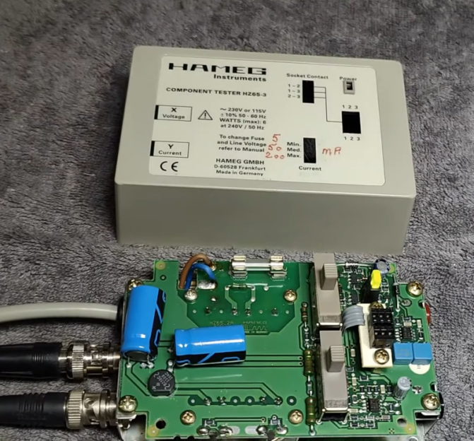
In the modern age, when you hear “component tester” you probably think of one of those cheap microcontroller-based devices that can identify components and provide basic measurements on an LCD screen. However, in the past, these were usually simple circuits that generated an XY scope plot. The trace would allow an experienced operator to identify components and read a few key parameters. [Thomas] tears down an old Hameg device that uses this principle in the video below.

The unit is in a nice enclosure and has a feature that controls the amount of current the unit uses in the excitation signal. It plugs into the wall, and you can connect the component under test with either test leads or a socket. The output, of course, is a pair of BNCs for the scope’s X and Y inputs.

Compared to some homebrew projects that are similar, the PCB inside the device seems more complex. The output of most devices like this uses the line frequency (50 or 60 Hz). This one, however, has its own drive oscillator that operates at a different frequency.

Each type of component has a tell-tale trace on the scope. We found the tunnel diode trace especially interesting. Capacitors are circles, diodes make a definite step shape. There’s a table from the manual near the end of the video.

Most of these devices are much simpler, using a transformer to generate the AC sweep and a simple mechanism to measure the current. That makes them quite easy to build and they are still surprisingly useful.

Building a DIY Nipkow Disk Display

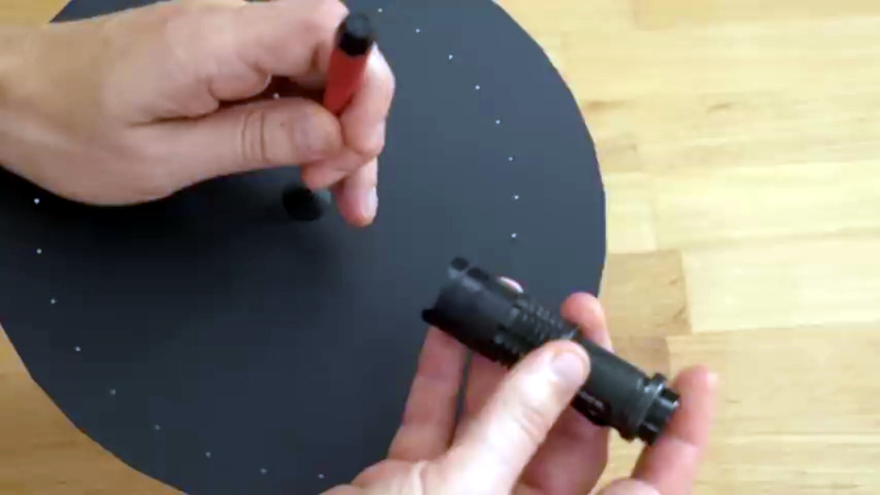
Before flat screen technologies took over, we associate TV with the CRT. But there were other display technologies that worked, they just weren’t as practical. One scheme was the Nipkow disk, and [Bitluni] decided to build a working demonstration of how such a system works.

Essentially, there’s a spinning disk with a spiral pattern of holes in it. As the disk spins, a light behind it turns on or off. If you time everything right, you get an image that can move. This particular model uses stepper motors, which is a bit of a modern concession.

The result was actually much better than you might guess, but a far cry from a modern display device, of course. The screen material needed a little tweaking, but even the initial results were very impressive. If this were trying to be practical, it would probably require a bit more work on the light source and screen.

Interestingly, the Nipkow disk arrangement was just as suitable for scanning as displaying. Instead of a light behind the wheel, you simply used a light sensor. Of course, in practice, getting everything synchronized and mass-producing high-resolution sets would have been a tremendous challenge a century ago.

Not that people didn’t try. There were even color systems using mechanical wheels. In the 1930s, people were sure your TV would contain spinning disks.

Inside an Arcade Joystick

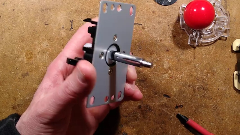
If you ever played an arcade game and wondered what was inside that joystick you were gripping, [Big Clive] can save you some trouble. He picked up a cheap replacement joystick, which, as you might expect, has a bunch of microswitches. However, as you can see in the video below, there are some surprising features that make sense when you think about it.

For one, there are plates you can put on the bottom to limit the joystick’s travel depending on the game. That is, some games only want the stick to move up and down or left and right. The knobs are quite nice, and [Clive] mentions the size and thread of the knob with the idea you could use them in different applications. You can also buy replacement knobs if you don’t want to get the whole assembly.

The mechanics are rugged but straightforward. The circuit board is surprisingly stylish but also simple. Still interesting to see what’s inside one of these, even though the schematic is extremely simple.

If you need an excuse to use one of these, how about an arcade table? If you aren’t a woodworker, grab a 3D printer instead.

Retrotechtacular: Computer-Generate Video 1968 Style!

[Classic Microcomputers] read in a book that there was a computer-generated film made in the late 1960s, and he knew he had to watch it. He found it and shared it along with some technical information in the video below.

Modern audiences are unlikely to be wowed by the film — Permutations — that looks like an electronic spirograph. But for 1968, this was about as high tech as you could get. The computer used was an IBM mainframe which would have cost a fortune either to buy or to rent the hours it would take to make this short film. Now, of course, you could easily replicate it on even your oldest PC. In fact, we are surprised we haven’t seen any recreations in the demoscene.

The end credits list [John Whitney] working under an IBM research grant as the author of the film. The programming was by [Jack Citron], and it was apparently put together at the UCLA School of Medicine.

According to [Classic Microcomputers], the display was static and black and white, but animation on 16mm film and color filters made it more interesting.

Was this the birth of the demoscene? Usually, when we watch old IBM videos, it is of the data center, not the data!

DIY Digital Caliper Measures Up

You might wonder why [Kevin] wanted to build digital calipers when you can buy them for very little these days. But, then again, you are reading Hackaday, so we probably don’t need to explain it.

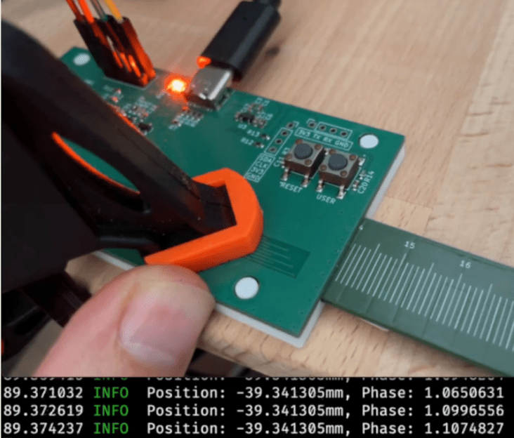
The motivation, in this case, was to learn to build the same mechanism the commercial ones use for use in precise positioning systems. We were especially happy to see that [Kevin’s] exploration took him to a Hackaday.io project which led to collaboration between him and [Mitko].

The theory behind the mechanism is simple but does get into some ugly-looking trigonometry. Electrically, you feed eight sine waves with different phases into the assembly and measure the phase of the signal you receive.

Pulse density modulation is sufficient for the driving signals. The math is a bit more complex, but nothing you can’t do with a modern CPU. To set the correct parameters, a PC-based test setup allowed different runs to determine the best parameters for the final implementation.

Of course, the whole thing still needs some packaging to use as either a practical pair of calipers or for unrelated positioning duty. But it does work and it should be straightforward to adapt it for any purpose.

We’ve looked inside calipers before. If you are only making measurements with calipers one way, you may be missing out.

Teaching a Pi Pico E-Ink Panel New Tricks

We’ve noticed that adding electronic paper displays to projects is getting easier. [NerdCave] picked up a 4.2-inch E-ink panel but found its documentation a bit lacking when it came to using the display under MicroPython. Eventually he worked it out, and was kind enough to share with the rest of the class.

These paper-like displays draw little power and can hold static images. There were examples from the vendor of how to draw some simple objects and text, but [NerdCave] wanted to do graphics. There was C code to do it, but it wasn’t clear how to port it to Python.

The key was to use the image2cpp website (we’ve used it before, but you can also use GIMP). Instead of C code, though, you get the raw bytes out and place them in your Python code. Once you know the workflow, it isn’t that hard, and this is an inexpensive way to add a different kind of display to your projects. The same image conversion will help you work with other displays, too.

We aren’t sure what driver chip this particular display uses, but if you have one with the UC8151/IL0373, you can find some amazing MicroPython drivers for those chips.

DIY Lock Nuts

If you have a metal lathe just looking for some work, why not make your own lock nuts? That’s what [my mechanics insight] did when faced with a peculiar lock nut that needed replacing in a car. We can’t decide what we enjoyed more in the video you can watch below: the cross-section cut of a lock nut or the oddly calming videos of the new nut being turned on a lathe.

The mystery of the lock nut, though, isn’t how it works. The nylon insert is just a little too small for the bolt, and the bolt, being harder than nylon, taps a very close-fitting hole in the nylon as you tighten it. The real mystery is how that nylon got in there to start with.

As the video shows, you fabricate the nut with an open area to accept the nylon ring. Then, you use a tool to crimp the edges down to trap the ring. The video shows all the pieces being made: the nut, the ring, and the crimping tool.

As you might deduce, the crimping tool has to be harder than the nut material, so that takes some extra effort. But all the work is done on the lathe except the crimping. He uses a vise, but we’d imagine that an arbor press is more commonly used.

Lock washers and nuts seem like a simple topic, but it is way more complex than you probably thought. Way more complex.

Thanks to [the gambler] for the tip!

Reviewing the World’s 2nd Smallest Thermal Camera

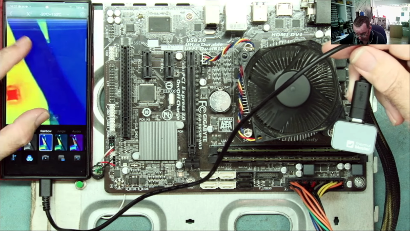
A thermal camera is a very handy tool to have, and [Learn Electronics Repair] wanted to try out the Thermal Master P2 for electronic repair, especially since it claims to have a 15 X digital zoom and 1.5 degree accuracy. The package proudly states the device is the “World 2nd Smallest Thermal Camera” — when only the second best will do.

The camera is tiny and connects to a PC or directly to a tablet or phone via USB C. However, it did look easier to use on the end of a cable for probing things like a PC motherboard. The focus was fairly long, so you couldn’t get extremely close to components with the camera. The zoom somewhat makes up for that, but of course, as you might expect, zooming in doesn’t give you any additional resolution.

He also compares the output with that of a multimeter he uses that includes an IR camera (added to our holiday gift list). That multimeter/camera combo focuses quite closely, which is handy when picking out a specific component. It also has a macro lens, which can zoom up even more.

We’ve looked at — or, more accurately, through — IR cameras in the past. If you are on a tight budget and you have a 3D printer, you might try this method for thermal imaging, but it doesn’t use the printer the way you probably think.

❌