Component Tester Teardown

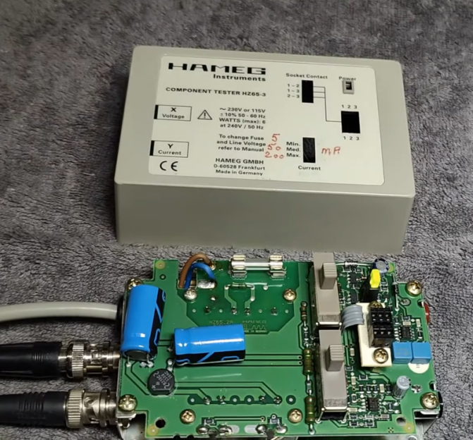
In the modern age, when you hear “component tester” you probably think of one of those cheap microcontroller-based devices that can identify components and provide basic measurements on an LCD screen. However, in the past, these were usually simple circuits that generated an XY scope plot. The trace would allow an experienced operator to identify components and read a few key parameters. [Thomas] tears down an old Hameg device that uses this principle in the video below.
The unit is in a nice enclosure and has a feature that controls the amount of current the unit uses in the excitation signal. It plugs into the wall, and you can connect the component under test with either test leads or a socket. The output, of course, is a pair of BNCs for the scope’s X and Y inputs.
Compared to some homebrew projects that are similar, the PCB inside the device seems more complex. The output of most devices like this uses the line frequency (50 or 60 Hz). This one, however, has its own drive oscillator that operates at a different frequency.
Each type of component has a tell-tale trace on the scope. We found the tunnel diode trace especially interesting. Capacitors are circles, diodes make a definite step shape. There’s a table from the manual near the end of the video.
Most of these devices are much simpler, using a transformer to generate the AC sweep and a simple mechanism to measure the current. That makes them quite easy to build and they are still surprisingly useful.