Vista de Lectura

Hay nuevos artículos disponibles. Pincha para refrescar la página.

A Surprisingly Simple Omnidirectional Display
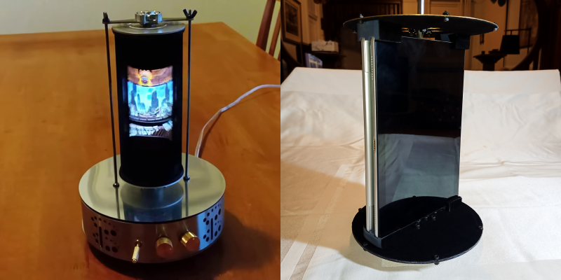
Old-school technology can spark surprising innovations. By combining the vintage zoetrope concept with digital displays, [Mike Ando] created the Andotrope, a surprisingly simple omnidirectional display.

Unlike other 3D displays, the Andotrope lets you view a normal 2D video or images that appear identical irrespective of your viewing angle. The prototype demonstrated in the video below consists of a single smart phone and a black cylinder spinning at 1,800 RPM. A narrow slit in front of each display creates a “scanning” view that our brain interprets as a complete image, thanks to persistence of vision. [Mike] has also created larger version with a higher frame rate, by mounting two tablets back-to-back.

Surprisingly, the Andotrope appears to be an original implementation, and neither [Mike] nor we can find any similar devices with a digital display. We did cover one that used a paper printout in a a similar fashion. [Mike] is currently patenting his design, seeing the potential for smaller displays that need multi-angle visibility. The high rotational speed creates significant centrifugal force, which might limit the size of installations. Critically, display selection matters — any screen flicker becomes glaringly obvious at speed.

This device might be the first of its kind, but we’ve seen plenty of zoetropes over the years, including ones with digital displays or ingenious time-stretching tricks.
Tearing Down A SLA Printer With The Engineers Who Built It

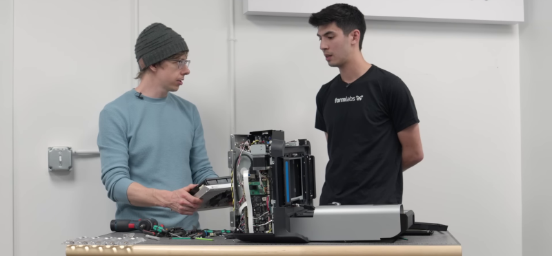
Product teardowns are great, but getting an unfiltered one from the people who actually designed and built the product is a rare treat. In the lengthy video after the break, former Formlabs engineer [Shane Wighton] tears down the Form 4 SLA printer while [Alec Rudd], the engineering lead for the project, answers all his prying questions.

[Shane] was part of the team that brought all Form 4’s predecessors to life, so he’s intimately familiar with the challenges of developing such a complex product. This means he can spot the small design details that most people would miss, and dive into the story behind each one. These include the hinges and poka-yoke (error-proofing) designed into the lid, the leveling features in the build-plate mount, the complex prototyping challenges behind the LCD panel and backlight, and the mounting features incorporated into every component.

A considerable portion of the engineering effort went into mitigating all the ways things could go wrong in production, shipping, and operation. The fact that most of the parts on the Form 4 are user-replaceable makes this even harder. It’s apparent that both engineers speak from a deep well of hard-earned experience, and it’s well worth the watch if you dream of bringing a physical product to market.

You probably know [Shane] from his YouTube channel Stuff Made Here. We’ve covered many of his ludicrously challenging projects, like the auto-aiming pool cue and golf club, a robotic hairdresser, and an “unpickable” lock.

A Very Fast Camera Slider For The Glam Shot

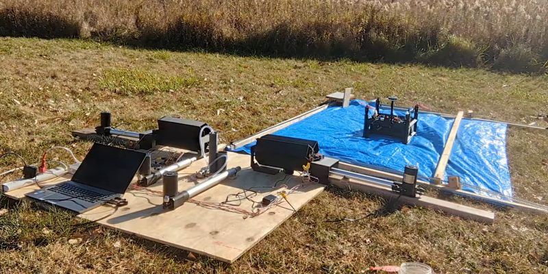
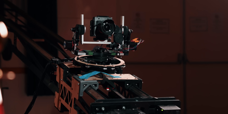
High-speed photography with the camera on a fast-moving robot arm has become all the rage at red-carpet events, but this GlamBOT setup comes with a hefty price tag. To get similar visual effects on a much lower budget [Henry Kidman] built a large, very fast camera slider. As is usually the case with such projects, it’s harder than it seems.

The original GlamBOT has a full 6 degrees of freedom, but many of the shots it’s famous for are just a slightly curved path between two points. That curve adds a few zeros to the required budget, so a straight slider was deemed good enough for [Henry]’s purposes. The first remaining challenge is speed. V1 one used linear rails made from shower curtain rails, with 3D printed sliders driven by a large stepper motor via a belt. The stepper motor wasn’t powerful enough to achieve the desired acceleration, so [Henry] upgraded to a more powerful 6 hp servo motor.

Unfortunately, the MDF and 3D-printed frame components were not rigid enough for the upgraded torque. It caused several crashes into the ends of the frame as the belt slipped and failed to stop the camera platform. The frame was rebuilt from steel, with square tubing for the rails and steel plates for the brackets. It provided the required rigidity, but the welding had warped the rails which led to a bumpy ride for the camera so he had to use active stabilization on the gimbal and camera. This project was filled with setback and challenges, but in the end the results look very promising with great slow motion shots on a mock red carpet.

We’ve seen DIY camera sliders of all shapes and sizes, including ones made from skateboard trucks and wood, and even a measuring tape.

Automated Weed Spraying Drone Needs No Human Intervention

Battling weeds can be expensive, labor intensive and use large amounts of chemicals. To help make this easier [NathanBuilds] has developed  V2 of his open-source drone weed spraying system, complete with automated battery swaps, herbicide refills, and an AI vision system for weed identification.

The drone has a 3D printed frame, doubling as a chemical reservoir. V1 used a off-the-shelf frame, with separate tank. Surprisingly, it doesn’t look like [Nathan] had issues with leaks between the layer lines. For autonomous missions, it uses ArduPilot running on a PixHawk, coupled with RTK GPS for cm-level accuracy and a LiDAR altimeter. [Nathan] demonstrated the system in a field where he is trying to eradicate invasive blackberry bushes while minimizing the effect on the native prairie grass. He uses a custom image classification model running on a Raspberry Pi Zero, which only switches on the sprayers when it sees blackberry bushes in the frame. The Raspberry Pi Global Shutter camera is used to get blur-free images.

At just 305×305 mm (1×1 ft), the drone has limited herbicide capacity, and we expect the flights to be fairly short. For the automated pit stops, the drone lands on a 6×8 ft pad, where a motorized capture system pulls the drone into the reload bay. Here a linear actuator pushes a new battery into the side of the drone while pushing the spend battery one out the other side. The battery unit is a normal LiPo battery in 3D-printed frame. The terminal are connected to copper wire and tape contacts on the outside the battery unit, which connect to matching contacts in the drone and charging receptacles. This means the battery can easily short if it touches a metal surface, but a minor redesign could solve this quickly. There are revolving receptacles on either side of the reload bay, which immediately start charging the battery when ejected from the drone.

Developing a fully integrated system like this is no small task, and it shows a lot of potential. It might look a little rough around the edges, but [Nathan] has released all the design files and detailed video tutorials for all the subsystems, so it’s ready for refinement.

Fix That Old Remote With Graphite

A button that stopped working has probably led to more than a few smashed remotes over the years. Fortunately [pescado99] has shared a beautifully simple cure for dead or dying remote buttons: graphite dry lubricant.

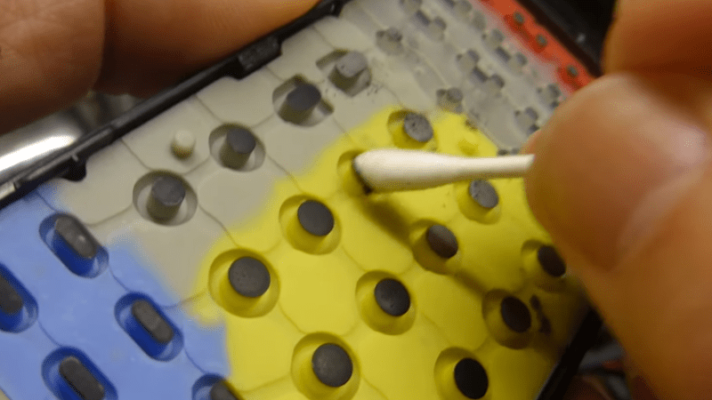
Most remotes operate by pushing a conductive carbon coating on the back of the button onto a pair of contacts on the PCB. Unfortunately, that conductive coating can wear off, leaving you with a dead or dying button. The video after the break [pescado99] demonstrates how to use a cotton swab to apply powdered graphite to the rear of the buttons to make them conductive again. A soft pencil can also be used, but the graphite works better.

This beautifully simple hack is too good not to share and could save many remotes from landfills. If you’re more interested in upgrading remote, you can build your own universal remote or replace it with a web browser.

Combining Gyro Stabilisation With Weight Shift Balancing

Gyroscopes are perfect to damper short impulses of external forces but will eventually succumb if a constant force, like gravity, is applied. Once the axis of rotation of the mass aligns with the axis of the external torque, it goes into the gimbal lock and loses the ability to compensate for the roll on that axis. [Hyperspace Pirate] tackled this challenge on a gyroscopically stabilized RC bike by shifting a weight around to help keep the bike upright.

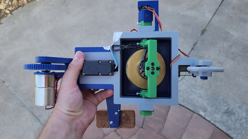
[Hyperspace Pirate] had previously stabilized a little monorail train with a pair of control moment gyroscopes. They work by actively adjusting the tilt of gyroscopes with a servo to apply a stabilizing torque. On this bike, he decided to use the gyro as a passive roll damper, allowing it to rotate freely on the pitch axis. The bike will still fall over but at a much slower rate, and it buys time for a mass on the end of the servo-actuated arm to shift to the side. This provides a corrective torque and prevents gimbal lock.

[Hyperspace Pirate] does an excellent job of explaining the math and control theory behind the system. He implemented a PD-controller (PID without the integral) on an Arduino, which receives the roll angle (proportional) from the accelerometer on an MPU6050 MEMS sensor and the roll rate (Derivative) from a potentiometer that measures the gyro’s tilt angle. He could have just used the gyroscope output from the MPU6050, but we applaud him for using the actual gyro as a sensor.

Like [Hyperspace Pirate]’s other projects, aesthetics were not a consideration. Instead, he wants to experiment with the idea and learn a few things in the process, which we can support.

Bogey Six O’clock!: The AN/APS-13 Tail Warning Radar

Although we think of air-to-air radar as a relatively modern invention, it first made its appearance in WWII. Some late war fighters featured the AN/APS-13 Tail Warning Radar to alert the pilot when an enemy fighter was on his tail. In [WWII US Bombers]’ fascinating video we get a deep dive into this fascinating piece of tech that likely saved many allied pilots’ lives.

Fitted to aircraft like the P-51 Mustang and P-47 Thunderbolt, the AN/APS-13 warns the pilot with a light or bell if the aircraft comes within 800 yards from his rear. The system consisted of a 3-element Yagi antenna on the vertical stabilizer, a 410 Mhz transceiver in the fuselage, and a simple control panel with a warning light and bell in the cockpit.

In a dogfight, this allows the pilot to focus on what’s in front of him, as well as helping him determine if he has gotten rid of a pursuer. Since it could not identify the source of the reflection, it would also trigger on friendly aircraft, jettisoned wing tanks, passing flak, and the ground. This last part ended up being useful for safely descending through low-altitude clouds.

This little side effect turned out to have very significant consequences. The nuclear bombs used on Hiroshima and Nagasaki each carried four radar altimeters derived from the AN/APS-13 system.

Portable Solder Paste Station Prevents Smears With Suction

Applying solder paste to a new custom PCB is always a little nerve-racking. One slip of the hand, and you have a smeared mess to clean up. To make this task a little easier, [Max Scheffler] built the Stencil Fix Portable, a compact self-contained vacuum table to hold your stencil firmly in place and pop it off cleanly every time.

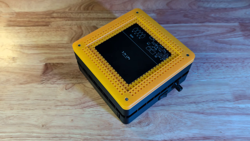
The Stencil Fix V1 used a shop vac for suction, just like another stencil holder we’ve seen. The vacuum can take up precious space, makes the jig a little tricky to move, and bumping the hose can lead to the dreaded smear and colorful language. To get around this [Max] added a brushless drone motor with a 3D printed impeller, with a LiPo battery for power. The speed controller gets its PWM signal from a little RP2040 dev board connected to a potentiometer. [Max] could have used a servo tester, but he found the motor could be a little too responsive and would move the entire unit due to inertia from the impeller. The RP2040 allowed him to add a low pass filter to eliminate the issue. The adjustable speed also means the suction force can be reduced a little for easy alignment of the stencil before locking it down completely.

We love seeing tool projects like these that make future projects a little easier. Fortunately, [Max] made the designs available so you can build your own.

Small Steam Generator Creates Educational Experience

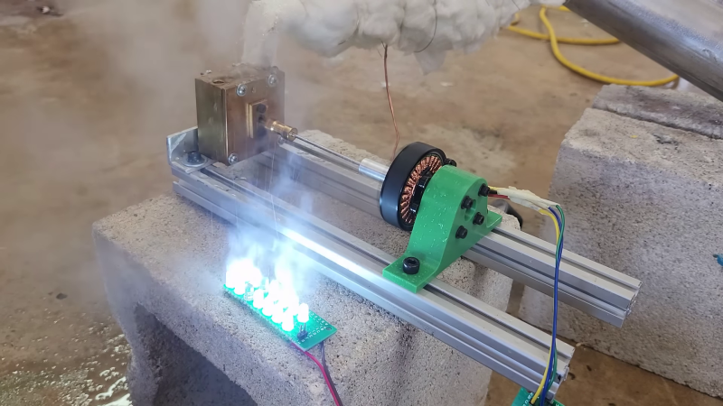
Steam turbines have helped drive a large chunk of our technological development over the last century or so, and they’ll always make for interesting DIY. [Hyperspace Pirate] built a small turbine and boiler in his garage, turning fire into flowing electrons, and learning a bunch in the process.

[Hyperspace Pirate] based the turbine design on 3D printed Pelton-style turbines he had previously experimented with, but milled it from brass using a CNC router. A couple of holes had to be drilled in the side of the rotor to balance it. The shaft drives a brushless DC motor to convert the energy from the expanding steam into electricity.

To avoid the long heat times required for a conventional boiler, [Hyperspace Pirate] decided to use a flash boiler. This involves heating up high-pressure water in a thin coil of copper tube, causing the water to boil as it flows down the tube. To produce the high-pressure water feed the propane tank for the burner was also hooked up to the water tank to pressurize it, removing the need for a separate pump or compressed air source. This setup allows the turbine to start producing power within twelve seconds of lighting the burner — significantly faster than a conventional boiler.

Throughout the entire video [Hyperspace Pirate] shows his calculation for the design and tests, making for a very informative demonstration. By hooking up a variable load and Arduino to the rectified output of the motor, he was able to measure the output power and efficiency. It came out to less than 1% efficiency for turning propane into electricity, not accounting for the heat loss of the boiler. The wide gaps between the turbine and housing, as well as the lack of a converging/diverging nozzle on the input of the turbine are likely big contributing factors to the low efficiency.

Like many of his other projects, the goal was the challenge of the project, not practicality or efficiency. From a gyro-stabilized monorail, to copper ingots from algaecide and and a DIY cryocooler, he has sure done some interesting ones.

Clockwork Rover For Venus

Venus hasn’t received nearly the same attention from space programs as Mars, largely due to its exceedingly hostile environment. Most electronics wouldn’t survive the 462 °C heat, never mind the intense atmospheric pressure and sulfuric acid clouds. With this in mind, NASA has been experimenting with the concept of a completely mechanical rover. The [Beardy Penguin] and a team of fellow students from the University of Southampton decided to try their hand at the concept—video after the break.

The project was divided into four subsystems: obstacle detection, mechanical computer, locomotion (tracks), and the drivetrain. The obstacle detection system consists of three (left, center, right) triple-rollers in front of the rover, which trigger inputs on the mechanical computer when it encounters an obstacle over a certain size. The inputs indicate the position of each roller (up/down) and the combination of inputs determines the appropriate maneuver to clear the obstacle. [Beardy Penguin] used Simulink to design the logic circuit, consisting of AND, OR, and NOT gates. The resulting 5-layer mechanical computer quickly ran into the limits of tolerances and friction, and the team eventually had trouble getting their design to work with the available input forces.

Due to the high-pressure atmosphere, an on-board wind turbine has long been proposed as a viable power source for a Venus rover. It wasn’t part of this project, so it was replaced with a comparable 40 W electric motor. The output from a logic circuit goes through a timing mechanism and into a planetary gearbox system. It changes output rotation direction by driving the planet gear carrier with the sun gear or locking it in a stationary position.

As with many undergraduate engineering projects, the physical results were mixed, but the educational value was immense. They got individual subsystems working, but not the fully integrated prototype. Even so, they received several awards for their project and even came third in an international Simulink challenge. It also allowed another team to continue their work and refine the subsystems.

❌