Vista de Lectura

Hay nuevos artículos disponibles. Pincha para refrescar la página.

Drilling Rig Makes Accurate Holes In Seconds
Drilling holes can be quite time consuming work, particularly if you have to drill a lot of them. Think about all the hassle of grabbing a part, fixturing it in the drill press, lining it up, double checking, and then finally making the hole. That takes some time, and that’s no good if you’ve got lots of parts to drill. There’s an easy way around that, though. Build yourself a rad jig like [izzy swan] did.

The first jig we get to see is simple. It has a wooden platter, which hosts a fixture for a plastic enclosure to slot perfectly into place. Also on the platter is a regular old power drill. The platter also has a crank handle which, when pulled, pivots the platter, runs the power drill, and forces it through the enclosure in the exact right spot. It’s makes drilling a hole in the enclosure a repeatable operation that takes just a couple of seconds. The jig gets it right every time.

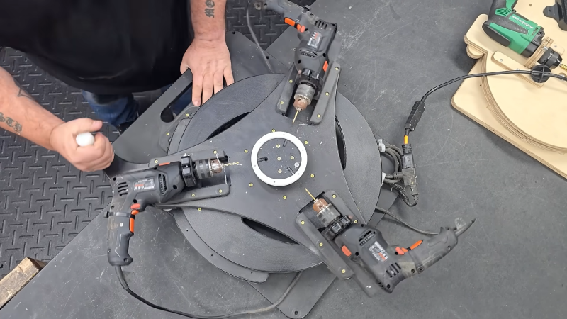
The video gets better from there, though. We get to see even niftier jigs that feature multiple drills, all doing their thing in concert with just one pull of a lever. [izzy] then shows us how these jigs are built from the ground up. It’s compelling stuff.

If you’re doing any sort of DIY manufacturing in real numbers, you’ve probably had to drill a lot of holes before. Jig making skills could really help you if that’s the case. Video after the break.

Build Yourself A Useful Resistor Decade Box

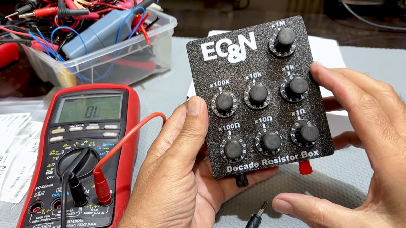
If you’ve ever worked with guitar pedals or analog audio gear, you’ve probably realized the value of a resistor decade box. They substitute for a resistor in a circuit and let you quickly flick through a few different values at the twist of a knob. You can still buy them if you know where to look, but [M Caldeira] decided to build his own.

At its core, the decade box relies on a number of 11-position rotary switches. Seven are used in this case—covering each “decade” of resistances, from 1 ohm to 10 ohm and all the way up to 1 megaohm. The 11 positions on each switch allows the selection of a given resistance. For example, position 7 on the 100 ohm switch selects 700 ohms, and adds it to the total resistance of the box.

[M Caldeira] did a good job of building the basic circuit, as well as assembling it in an attractive, easy-to-use way. It should serve him well on his future audio projects and many others besides. It’s a simple thing, but sometimes there’s nothing more satisfying than building your own tools.

We’ve seen other neat designs like this in the past, including an SMD version and this neat digital decade box. Video after the break.

FREE-WILi Turns DC32 Badge Into Hardware Dev Tool

With few exceptions, electronic event badges are often all but forgotten as soon as the attendee gets back home. They’re a fun novelty for the two or three days they’re expected to be worn, but after that, they end up getting tossed in a drawer (or worse.) As you might imagine, this can be a somewhat depressing thought thought for the folks who design and build these badges.

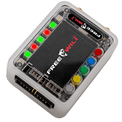
But thanks to a new firmware released by the FREE-WILi project, at least one badge is going to get a shot at having a second life. When loaded onto the RP2350-powered DEF CON 32 badge, the device is turned into a handy hardware hacking multi-tool. By navigating through a graphical interface, users will be able to control the badge’s GPIO pins, communicate over I2C, receive and transmit via infrared, and more. We’re particularly interested in the project’s claims that the combination of their firmware and the DC32 badge create an ideal platform for testing and debugging Simple Add-Ons (SAOs).

Don’t know what the FREE-WILi project is? Neither did we until today, which is actually kind of surprising now that we’re getting a good look at it. Basically, it’s a handheld gadget with a dozen programmable GPIO pins and a pair of CC1101 sub-GHz radios that’s designed to talk to…whatever you could possibly want to interface with.

It’s a bit like an even more capable Bus Pirate 5, which considering how many tricks that particular device can pull off, is saying something. As an added bonus, apparently you can even wear the FREE-WILi on your wrist for mobile hardware hacking action!

Anyway, while the hardware in the FREE-WILi is clearly more capable than what’s under the hood of the DC32 badge, there’s enough commonality between them that the developers were able to port a few of the key features over. It’s a clever idea — there’s something like 30,000 of these badges out there in the hands of nerds all over the world, and by installing this firmware, they’ll get a taste of what the project is capable of and potentially spring for the full kit.

If you give your DC32 badge the FREE-WILi treatment, be sure to let us know in the comments.

Power Supply With Benchtop Features Fits In Your Pocket

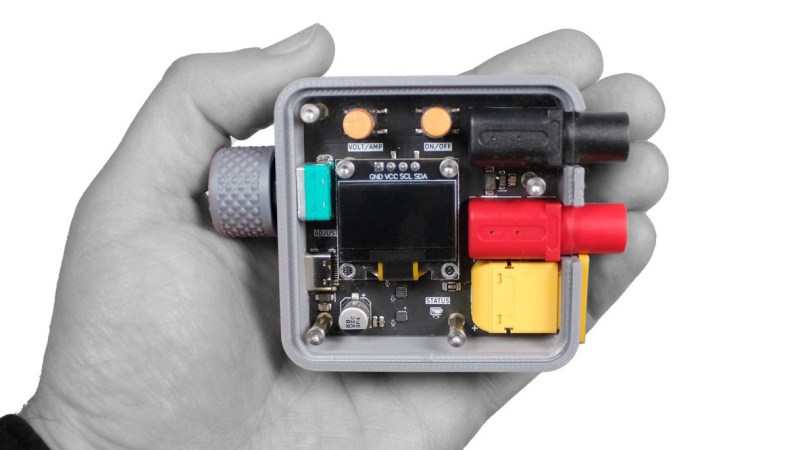
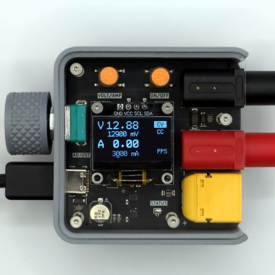
[CentyLab]’s PocketPD isn’t just adorably tiny — it also boasts some pretty useful features. It offers a lightweight way to get a precisely adjustable output of 0 to 20 V at up to 5 A with banana jack output, integrating a rotary encoder and OLED display for ease of use.

PocketPD leverages USB-C Power Delivery (PD), a technology with capabilities our own [Arya Voronova] has summarized nicely. In particular, PocketPD makes use of the Programmable Power Supply (PPS) functionality to precisely set and control voltage and current. Doing this does require a compatible USB-C charger or power bank, but that’s not too big of an ask these days.

Even if an attached charger doesn’t support PPS, PocketPD can still be useful. The device interrogates the attached charger on every bootup, and displays available options. By default PocketPD selects the first available 5 V output mode with chargers that don’t support PPS.

The latest hardware version is still in development and the GitHub repository has all the firmware, which is aimed at making it easy to modify or customize. Interested in some hardware? There’s a pre-launch crowdfunding campaign you can watch.

It’s a Soldering Iron! It’s A Multimeter! Relax! It’s Both!

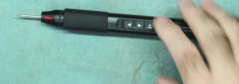
Imagine this. A young person comes to you wanting to get started in the electronic hobby. They ask what five things should they buy to get started. Make your list. We’ll wait. We bet we can guess at least two of your items: a multimeter, and a soldering iron. [LearnElectroncsRepair] recently showed us a review of the Zotek Zoyi ZT-N2 which is a soldering iron and a multimeter in one unit. You can watch the video review below.

Honestly, when we heard about this, we didn’t think much of the combination. It doesn’t seem like having your probe get red hot is a feature. However, the probe tip replaces the soldering iron tip, so you are either soldering or measuring, but not both at the same time.

The soldering iron part looks a lot like a T100 iron with a USB connector and a little LCD screen. The device is portable, so it has a little cheap soldering iron stand. As a multimeter, it does all the basic tests, but it is only usable for low-voltage applications under 36V.

The negative lead plugs into the USB connector, so the meter runs off an internal battery. While it looks like it is usable, we couldn’t really think of many cases where this would be handy unless you are really trying to pack a lot in a small space. We’d rather throw a small meter in the bag and call it a day.

In 2017, these little soldering irons were a fresh fad. Now, they are pretty common.

Component Tester Teardown

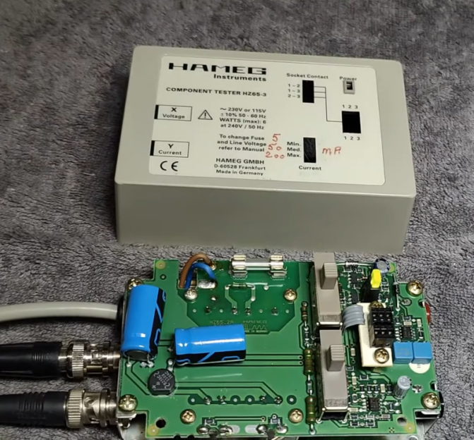
In the modern age, when you hear “component tester” you probably think of one of those cheap microcontroller-based devices that can identify components and provide basic measurements on an LCD screen. However, in the past, these were usually simple circuits that generated an XY scope plot. The trace would allow an experienced operator to identify components and read a few key parameters. [Thomas] tears down an old Hameg device that uses this principle in the video below.

The unit is in a nice enclosure and has a feature that controls the amount of current the unit uses in the excitation signal. It plugs into the wall, and you can connect the component under test with either test leads or a socket. The output, of course, is a pair of BNCs for the scope’s X and Y inputs.

Compared to some homebrew projects that are similar, the PCB inside the device seems more complex. The output of most devices like this uses the line frequency (50 or 60 Hz). This one, however, has its own drive oscillator that operates at a different frequency.

Each type of component has a tell-tale trace on the scope. We found the tunnel diode trace especially interesting. Capacitors are circles, diodes make a definite step shape. There’s a table from the manual near the end of the video.

Most of these devices are much simpler, using a transformer to generate the AC sweep and a simple mechanism to measure the current. That makes them quite easy to build and they are still surprisingly useful.

A Beautifully Illustrated Guide to Making

A light grey background with white and black line drawings of three different bicycles on one page and three different tire levers and three different valve covers for bikes on the other.

If you’ve ever been wondering what you should make next, it can be a daunting task to decide with the firehose of inspiration coming straight from the series of tubes that makeup the World Wide Web. Perhaps a more curated digital catalog of projects would help?

Featuring “1000 Useful Things to Make,” [NODE]’s Make it Yourself is a beautifully-illustrated catalog of open source and DIY projects spanning a number of domains including camping gear, furniture, music, and maker tools. Each image is a link to the original project and there’s a handy icon by each denoting what skills are needed, such as sewing or 3D printing.

If you haven’t seen [NODE]’s work before, he uses line art to illustrate his projects and has given all of these projects the same treatment on the (virtual) page with credits to the original creators in the footnotes. We hope a future edition will include tractors and houses to truly rival the Sears catalog of yore, but it’s hard to complain when we already have so many projects we could choose to build.

Many of the projects may seem familiar, if slightly fancier when illustrated in line art, like the Ploopy headphones, this retro audio player, or the Keybon adaptive macro pad.

Combination Safety Glasses and Measurement Tool

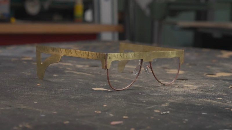
A set of brass safety glasses sit on a marred black workbench. The top and earpiece sections of the frames are in squarish brass plate and have ruler marks on them.

While rulers and tape measures are ubiquitous, they always seem to disappear when you need them. We know you’d never forget your safety glasses (safety first!), so what if they were also a measuring tool?

Starting by snapping pieces from a folding yardstick, [Simone Giertz] and [Laura Kampf] worked out a rough prototype before letting [Giertz] complete the project in brass. Some initial issues with the weight of the frames were alleviated by switching to a lighter weight plate material and using thinner frames and weight-saving holes near the ear pieces.

Beauty is in the eye of the beholder, so we’ll let somebody else decide whether or not these will be the newest fashion craze. But it’s hard to argue with the timelessness of brass unless you have a copper allergy. We could definitely see a less expensive plastic version catching on in makerspaces for the PPE bin.

Want some other cool wearable gear? How about [Giertz]’s grocery bag hat, an evening gown with servo-driven flowers, or a shirt that reflects heat out the atmospheric window?

Reviewing the World’s 2nd Smallest Thermal Camera

A thermal camera is a very handy tool to have, and [Learn Electronics Repair] wanted to try out the Thermal Master P2 for electronic repair, especially since it claims to have a 15 X digital zoom and 1.5 degree accuracy. The package proudly states the device is the “World 2nd Smallest Thermal Camera” — when only the second best will do.

The camera is tiny and connects to a PC or directly to a tablet or phone via USB C. However, it did look easier to use on the end of a cable for probing things like a PC motherboard. The focus was fairly long, so you couldn’t get extremely close to components with the camera. The zoom somewhat makes up for that, but of course, as you might expect, zooming in doesn’t give you any additional resolution.

He also compares the output with that of a multimeter he uses that includes an IR camera (added to our holiday gift list). That multimeter/camera combo focuses quite closely, which is handy when picking out a specific component. It also has a macro lens, which can zoom up even more.

We’ve looked at — or, more accurately, through — IR cameras in the past. If you are on a tight budget and you have a 3D printer, you might try this method for thermal imaging, but it doesn’t use the printer the way you probably think.

Rapid Prototyping PCBs With The Circuit Graver

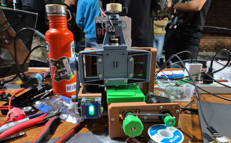
Walking around the alley at Hackaday Supercon 2024, we noticed an interesting project was getting quite a bit of attention, so we got nearer for a close-up. The ‘Circuit Graver’ by [Zach Fredin] is an unconventional PCB milling machine, utilizing many 3D printed parts, the familiar bed-slinger style Cartesian bot layout and a unique cutting head. The cutting tool, which started life as a tungsten carbide lathe tool, is held on a rotary (‘R’) axis but can also move vertically via a flexure-loaded carriage driven by a 13 kg servo motor.

The stocky flexure took a lot of iteration, as the build logs will show. Despite a wild goose chase attempting to measure the cutting force, a complete machine solution was found by simply making everything stiff enough to prevent the tool from chattering across the surface of the FR4 blank. Controlling and maintaining the rake angle was a critical parameter here. [Zach] actually took an additional step, which we likely wouldn’t have thought of, to have some copper blanks pre-fabricated to the required size and finished with an ENIG coating. It’s definitely a smart move!
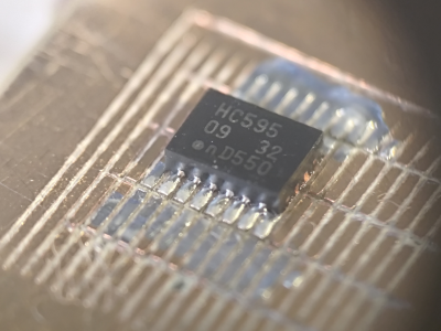
To allow the production of PCB-class feature sizes compatible with a traditional PCB router, the cutting tool was sharpened to a much smaller point than would be used in a lathe using a stone. This reduced the point size sufficiently to allow feature sizes down to 4 mils, or at least that’s what initial characterization implied was viable.  As you can see from the build logs, [Zach] has achieved a repeatable enough process to allow building a simple circuit using an SMT 74HC595 and some 0402 LEDs to create an SAO for this year’s Supercon badge. Neat stuff!

We see a fair few PCB mills, some 3D printed, and some not. Here’s a nice one that fits in that former category. Milling PCBs is quite a good solution for the rapid prototyping of electronics. Here’s a guide about that.

PicoROM, A DIP-32 8-Bit ROM Emulator

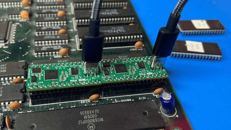
As we all know, when developing software for any platform or simply hacking a bit of code to probe how something works, the ability to deploy code rapidly is a huge help. [Martin Donlon], aka [wickerwaka], is well known in retro gaming and arcade hardware reverse engineering circles and had the usual issues figuring out how an arcade CPU board worked while developing a MiSTer core. Some interesting ASICs needed quite a bit of poking, and changing the contents of socketed ERPOMs is a labour-intensive process. The solution was PicoROM, a nicely designed ROM emulator in a handy DIP-32 form factor.

As the title suggests, PicoROM is based on the Raspberry Pi RP2040. It emulates an 8-bit ROM up to 2MBits in size with speeds up to 100ns. Since it uses the RP2040, USB connectivity is simple, enabling rapid uploading of new images to one (or more) PicoROMs in mere seconds. A vertically orientated USB-C connector allows multiple PicoROMs to be cabled to the host without interfering with neighbouring hardware. The firmware running on core 1 passes data from the internal 264K SRAM, using the PIO block as a bus interface to the target. A neat firmware feature is the addition of a mechanism to use a ROM region as a bidirectional control channel, which the software running on the target can use to communicate back to the host computer. This allows remote triggering of actions and the reporting of responses. Responses which may not be physically observable externally. [Martin] is using this feature extensively to help probe the functionality of some special function chips on the target boards, which is still a slow process but helped massively by reducing that critical software iteration time. The PCB was designed with KiCAD. The project files for which can be found here.

This isn’t the first time we’ve seen the RP2040 used for ROM emulation; here’s a pile of wires that does the same job. It just isn’t as pretty. Of course, if you really must use EPROMs, then you could give this sweet programmer a look over.

Polygons On a Lathe

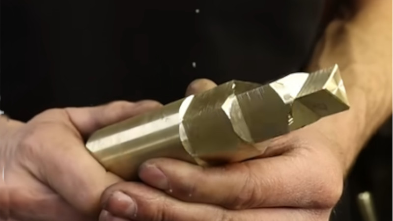
Man holding brass bar stock with several polygons turned on end

Most professionals would put a polygon on the end of a turned part using a milling machine. But many a hobbyist doesn’t have a mill. And if the polygon needs to be accurately centered, remounting the stock costs accuracy.

[Mehamozg] demonstrates you can turn a polygon on a lathe.

Polygons on shaft ends are surprisingly common, whether you are replacing a lost chuck key, need an angular index, or need a dismountable drive. As the video shows, you can definitely make them on the lathe.

But how the heck does this work? It seems like magic.

Lets start by imagining we disengage and lock the rotating cutter in [Mehamozg]’s setup and run the lathe. If the tool is pointed directly at the center we are just turning normally.  If we angle the tool either side of center we still get a cylinder, but the radius increases by the sin of the angle.

Now, if we take a piece of stock with a flat on it and plot radius versus angle we get a flat line with a sin curve dip in it. So if we use [Mehamozg]s setup and run the cutter and chuck at the same speed, the cutter angle and the stock angle increase at the same time, and we end up with a flat on the part.  If the cutter is rotating an even multiple of the chuck speed, we get a polygon.

The rub in all this is the cutter angle.. At first we were convinced it was varying enormously. But the surface at the contact point is not perpendicular to  the radius from center to contact. So it cancels out, we think.  But our brains are a bit fried by this one. Opinions in the comments welcomed.

We like this hack. It’s for a commonly needed operation, and versatile enough  to be worth fiddling with the inevitable pain of doing it the first time.  For a much more specialized machining hack, check out  this tool that works much the same in the other axis.

Portable Solder Paste Station Prevents Smears With Suction

Applying solder paste to a new custom PCB is always a little nerve-racking. One slip of the hand, and you have a smeared mess to clean up. To make this task a little easier, [Max Scheffler] built the Stencil Fix Portable, a compact self-contained vacuum table to hold your stencil firmly in place and pop it off cleanly every time.

The Stencil Fix V1 used a shop vac for suction, just like another stencil holder we’ve seen. The vacuum can take up precious space, makes the jig a little tricky to move, and bumping the hose can lead to the dreaded smear and colorful language. To get around this [Max] added a brushless drone motor with a 3D printed impeller, with a LiPo battery for power. The speed controller gets its PWM signal from a little RP2040 dev board connected to a potentiometer. [Max] could have used a servo tester, but he found the motor could be a little too responsive and would move the entire unit due to inertia from the impeller. The RP2040 allowed him to add a low pass filter to eliminate the issue. The adjustable speed also means the suction force can be reduced a little for easy alignment of the stencil before locking it down completely.

We love seeing tool projects like these that make future projects a little easier. Fortunately, [Max] made the designs available so you can build your own.

RF Detector Chip Helps Find Hidden Cameras and Bugs

It’s a staple of spy thriller movies, that the protagonist has some kind of electronic scanner with which he theatrically searches his hotel room to reveal the bad guys’ attempt to bug him. The bug of course always had a flashing LED to make it really obvious to viewers, and the scanner was made by the props department to look all cool and futuristic.

It’s not so far-fetched though, while bugs and hidden cameras in for example an Airbnb may not have flashing LEDs, they still emit RF and can be detected with a signal strength meter. That’s the premise behind [RamboRogers]’ RF hunter, the spy movie electronic scanner made real.

At the rear of the device is an ESP32, but the front end is an AD8317 RF detector chip. This is an interesting and useful component, in that it contains a logarithmic amplifier such that it produces a voltage proportional to the RF input in decibels. You’ll find it at the heart of an RF power meter, but it’s also perfect for a precision field strength meter like this one. That movie spy would have a much higher chance of finding the bug with one of these.

For the real spies of course, the instruments are much more sophisticated.

A 3D Printed, Open Source Lathe?

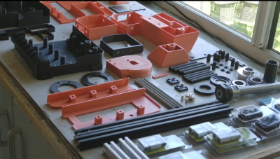
[Chris Borge] has spent the last few years creating some interesting 3D printed tools and recently has updated their 3D printable lathe design to make a few improvements. The idea was to 3D print the outer casing of the lathe in two parts, adding structural parts where needed to bolt on motors and tool holders, and then fill the whole thing with concrete for strength and rigidity.

Only a few parts to print

The printed base is initially held together with two lengths of studding, and a pile of bolts are passed through from below, mating with t-nuts on the top. 2020 extrusion is used for the motor mount. The headstock is held on with four thread rods inserted into coupling nuts in the base. The headstock unit is assembled separately, but similarly; 3D printed outer shell and long lengths of studding and bolts to hold it together. Decent-sized tapered roller bearings make an appearance, as some areas of a machine tool really cannot be skrimped. [Chris] explains that the headstock is separate because this part is most likely to fail, so it is removable, allowing it to be replaced.

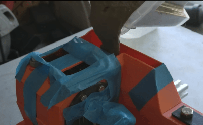
Yes, that’s right. We’re filling it with lovely runny concrete.
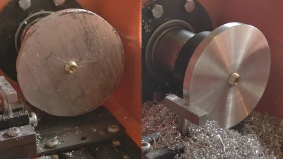
Not a bad job on aluminium for a DIY lathe!

Once together, the whole assembly is filled with runny concrete and set aside to cure. Before fully curing, the top surfaces are scraped flat to remove excess concrete so the top covers will fit. A belt-driven motor is fitted, with associated control electronics, and then it’s time to talk tooling. The first tool shown is a simple T-shaped rest, used with a hand tool known as a ‘graver.’  This is more likely to be used on a wood lathe, but we reckon you could about get away with it if you’re really careful with aluminium or perhaps brass. An adjustable rest was made using a few simple pieces (in steel!) and held in a short length of 2020 extrusion in a manner that makes it adjustable, albeit not shown in this video. Finally, a reasonable torture test is demonstrated, comprising a rough-cut aluminium disk screwed to a threaded carrier. This was tidied up to make it nice and round and clean up its surfaces. The lathe survived, only melting the 3D printed motor pulley, which, as they say, should not have been a 3D printed part when metal parts are so easy to acquire! If you want to build one for yourself, then everything you need is here, but like with projects of this type, more development is still needed to overcome a few shortcomings. Check out [Chris]’s channel for many more interesting ideas!

We’ve seen a few of [Chris]’s other 3D-printed tools, like this neat fractal vice for odd-shaped objects. We like tiny tool hacks; after all, when you’re making small things, you don’t need full-sized tools.

Thanks to [CJay] for the tip!

❌