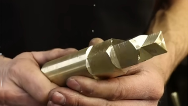
Polygons On a Lathe

Most professionals would put a polygon on the end of a turned part using a milling machine. But many a hobbyist doesn’t have a mill. And if the polygon needs to be accurately centered, remounting the stock costs accuracy.
[Mehamozg] demonstrates you can turn a polygon on a lathe.
Polygons on shaft ends are surprisingly common, whether you are replacing a lost chuck key, need an angular index, or need a dismountable drive. As the video shows, you can definitely make them on the lathe.
But how the heck does this work? It seems like magic.
Lets start by imagining we disengage and lock the rotating cutter in [Mehamozg]’s setup and run the lathe. If the tool is pointed directly at the center we are just turning normally. If we angle the tool either side of center we still get a cylinder, but the radius increases by the sin of the angle.
Now, if we take a piece of stock with a flat on it and plot radius versus angle we get a flat line with a sin curve dip in it. So if we use [Mehamozg]s setup and run the cutter and chuck at the same speed, the cutter angle and the stock angle increase at the same time, and we end up with a flat on the part. If the cutter is rotating an even multiple of the chuck speed, we get a polygon.
The rub in all this is the cutter angle.. At first we were convinced it was varying enormously. But the surface at the contact point is not perpendicular to the radius from center to contact. So it cancels out, we think. But our brains are a bit fried by this one. Opinions in the comments welcomed.
We like this hack. It’s for a commonly needed operation, and versatile enough to be worth fiddling with the inevitable pain of doing it the first time. For a much more specialized machining hack, check out this tool that works much the same in the other axis.