Vista de Lectura

Hay nuevos artículos disponibles. Pincha para refrescar la página.

Hackaday Links: January 12, 2025

Hackaday Links Column Banner

The big news story of the week of course has been the wildfires in California, which as of Saturday have burned over 30,000 acres, destroyed 12,000 structures, caused 150,000 people to evacuate, and killed eleven people. Actually, calling them wildfires underplays the situation a bit because there are places where they’ve clearly become firestorms, burning intensely enough to create their own winds, consuming everything in their path in a horrific positive feedback loop. We’ve even seen fire tornados caught on video. We’ve got quite a few connections to the affected area, both personally and professionally, not least of which are all our Supplyframe colleagues in Pasadena, who are under immediate threat from the Eaton fire. We don’t know many details yet, but we’ve heard that some have lost homes. We’ve also got friends at the Jet Propulsion Labs, which closed a few days ago to all but emergency personnel. The fire doesn’t seem to have made it down the mountain yet, but it’s very close as of Saturday noon.

Unfortunately, there’s not much any of us can do except watch and wait and hope for the best. But there is one thing we can not do, and that’s try to fly our drones around to get some video of the fire. That’s probably what some knucklehead was up to when a Canadian aerial tanker fighting the Pallisades fire sustained wing damage from a drone strike. The drone apparently hit the leading edge of one wing on the Canadair CL-145 Super Scooper, caving it in and grounding the plane. Taking an indispensable aerial asset like that out of the fight and endangering the lives of the crew and the firefighters working on the ground in close proximity to it is unforgivable, and the culprits better hope the authorities catch up to them before the justifiably angry victims of the fire do.

Speaking of other things not to do during a wildfire, you might want to think twice before keying up that Baofeng to call in a custom aerial water attack. That’s what the Federal Communications Commission accuses an Idaho amateur radio operator of doing during a 2021 fire near Elk River, Idaho, a stunt that’s going to cost him a cool $34,000 in fines. The FCC recently issued a forfeiture order that affirms the original judgment against Jason Frawley (WA7CQ). Our friend Josh (KI6NAZ) over at Ham Radio Crash Course has a great rundown on the FCC ruling and its implications, but the short story is that Frawley operated a radio outside of the bands he’s licensed to use to talk to US Forest Service aerial assets, apparently to call in a water drop in the area of a mountaintop repeater site. This created a dangerous enough situation that the incident commander left the fireground to find him and tell him to stop. Forest Service law enforcement officers later found Frawley and interviewed him, whereupon he admitted making the transmissions but said he was only trying to help. The FCC didn’t buy it, so now he’s on the hook for a huge fine. The lesson is simple — the FCC doesn’t mess around with enforcement, especially where public safety is involved.

On to more pleasant distractions! We got a tip on a fun website called Atlas of Space that you’ll want to check out. It’s an interactive visualization of the solar system which lets you see the current orbital locations of pretty much all the interesting stuff going around the sun. You can control which classes of objects are displayed, from the inner planets to the trans-Neptunian objects. There’s even a callout for Elon’s Roadster, which is currently outside the orbit of Mars, in case you wanted to know. The thing that’s nice is that you can control the view in three dimensions, which makes it easy to appreciate the complexity of our system. We never realized just how weird Pluto’s orbit was; it’s highly elliptical and very steeply inclined relative to the ecliptic. And that’s another thing — the plane of the ecliptic isn’t all that planar. The universe is a messy place, and our little corner of it is quite a bit more untidy than simple textbook illustrations would lead you to believe.

And finally, while a lot of progress has been made in making public places accessible to people in wheelchairs, there can still be significant barriers once they get inside a place. One we never thought of was the laboratory, where wheelchair users can face a slew of problems. Chief among them can be finding effective PPE like lab coats, which as any “lab rat” can tell you aren’t the easiest garments to sit down in. To remedy that, a group at University College London has come up with a prototype lab coat adapted for wheelchair use. It’s not clear what the modifications are, but if we had to guess we’d say it’s more or less a standard lab coat with the tails cut off, making it more like an apron from the waist down. The design group is currently testing the prototype and needs people to give it a try, so if you’re a wheelchair user working in a lab, drop them a line and let them know what you think.
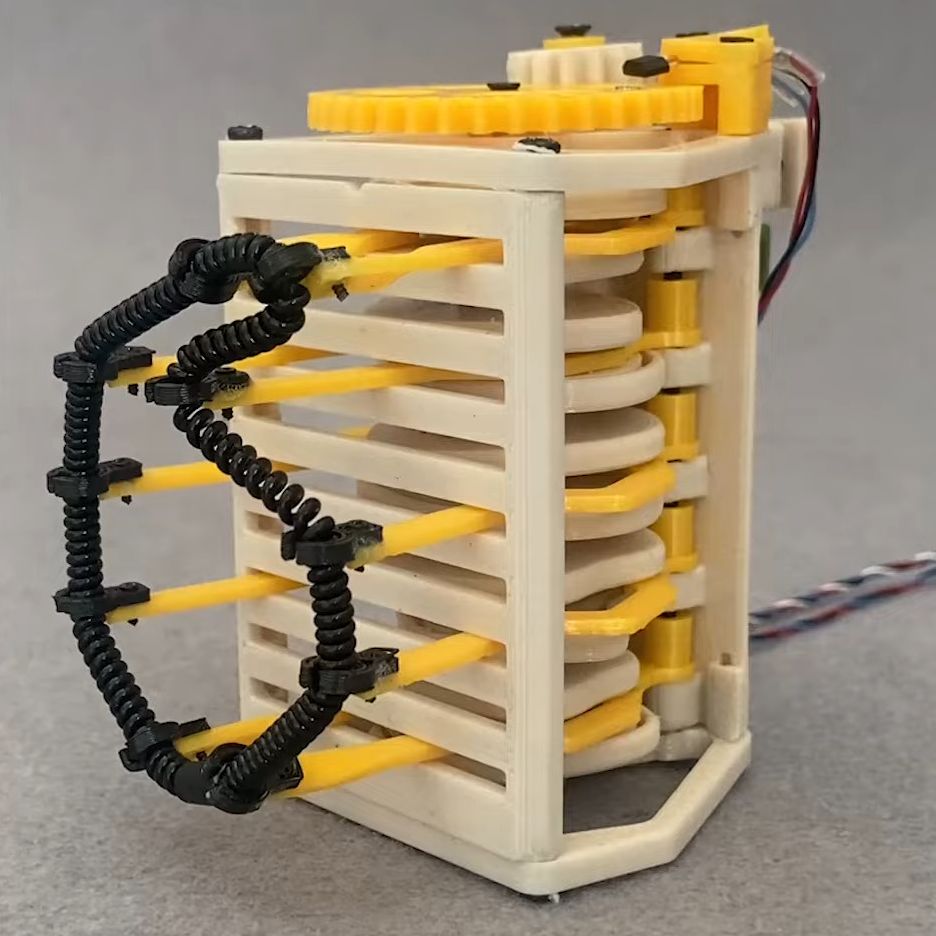
Springs and Things Make for a Unique Timepiece

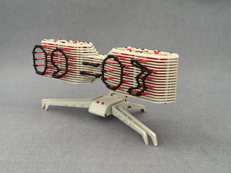
You never know when inspiration is going to strike, and for [Ekaggrat Singh Kalsi], it struck while he was playing with one of his daughter’s hair ties. The result is a clock called “Bezicron” and it’s a fascinating study in mechanical ingenuity.

The hair ties in question are simple objects, just a loose polymer coil spring formed into a loop that can be wrapped around ponytails and the like. In Bezicron, though, each digit is formed by one of these loops fixed to the ends of five pairs of arms. Each pair moves horizontally thanks to a cam rotating between them, changing the spacing between them and moving the hair tie. This forms each loop into an approximation of each numeral, some a little more ragged than others but all quite readable. The cams move thanks to a geared stepper motor on the rightmost digit of the hours and minutes section of the clock, with a gear train carrying over to the left digit. In between is the colon, also made from springy things pulsing back and forth to indicate seconds. The video below shows the clock going through its serpentine motions.

For our money, the best part of this build is the cams. Coming up with the proper shape for those had to be incredibly tedious, although we suspect 3D printing and rapid iterative design were a big help here. Practice with cam design from his earlier Eptaora clock probably helped too.

Thanks to [Hari Wiguna] for the tip.

RISC-V Microcontroller Lights Up Synth with LED Level Meter

The LM3914 LED bar graph driver was an amazing chip back in the day. Along with the LM3915, its logarithmic cousin, these chips gave a modern look to projects, allowing dancing LEDs to stand in for a moving coil meter. But time wore on and the chips got harder to find and even harder to fit into modern projects, what with their giant DIP-18 footprint. What’s to be done when a project cries out for bouncing LEDs? Simple — get a RISC-V microcontroller and roll your own LED audio level meter.

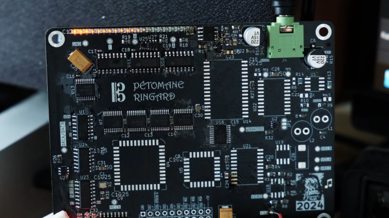
In fairness, “simple” isn’t exactly what comes to mind while reading [svofski]’s write-up of this project. It’s part of a larger build, a wavetable synth called “Pétomane Ringard” which just screams out for lots of blinky LEDs. [svofski] managed to squeeze 20 small SMD LEDs onto the board along with a CH32V003 microcontroller. The LEDs are charlieplexed, using five of the RISC-V chip’s six available GPIO lines, leaving one for the ADC input. That caused a bit of trouble with programming, since one of those pins is needed to connect to the programmer. This actually bricked the chip, thankfully only temporarily since there’s a way to glitch the chip back to life, but only after pulling it out of the circuit. [svofski] recommends adding a five-second delay loop to the initialization routine to allow time to recover if the microcontroller gets into an unprogrammable state. Good tip.

As for results, we think the level meter looks fantastic. [svofski] went for automated assembly of the 0402 LEDs, so the strip is straight and evenly spaced. The meter seems to be quite responsive, and the peak hold feature is a nice touch. It’s nice to know there’s a reasonable substitute for the LM391x chips, especially now that all the hard work has been done.

Engineering Lessons from the Super-Kamiokande Neutrino Observatory Failure

Every engineer is going to have a bad day, but only an unlucky few will have a day so bad that it registers on a seismometer.

We’ve always had a morbid fascination with engineering mega-failures, few of which escape our attention. But we’d never heard of the Super-Kamiokande neutrino detector implosion until stumbling upon [Alexander the OK]’s video of the 2001 event. The first half of the video below describes neutrinos in some detail and the engineering problems related to detecting and studying a particle so elusive that it can pass through the entire planet without hitting anything. The Super-Kamiokande detector was built to solve that problem, courtesy of an enormous tank of ultrapure water buried 1,000 meters inside a mountain in Japan and lined with over 10,000 supersized photomultiplier tubes to detect the faint pulses of Chernkov radiation emitted on the rare occasion that a neutrino interacts with a water molecule.

Those enormous PM tubes would be the trigger for the sudden demise of the Super-K , which is covered in the second half of the video. During operations to refill the observatory after routine maintenance, technicians noticed a bang followed by a crescendo of noise from the thirteen-story-tall tank. They quickly powered down the system and took a look inside the tank to find almost every PM tube destroyed. The resulting investigation revealed that the tubes had failed in sequence following the sudden implosion of a single tube at the bottom of the tank. That implosion caused a shock wave to propagate through the water to surrounding tubes which exceeded their design limits, causing further implosions and further destruction. The cascading implosion took a full ten seconds to finish its wave of destruction, which destroyed $7 million worth of tubes.

The interesting part about this is the root cause analysis, which boils down to the fact that you shouldn’t stand on 50-cm photomultiplier tubes. Also at fault was the testing regimen for the tubes, which the project engineers anticipated could cause a cascading implosion. They tested this but were unable to cause a cascade failure, leading them to the conclusion it wasn’t likely to happen. But analysis of the destruction revealed a flaw in the testing, which should give pause to anyone who ever had to design a test like this before.

Luckily, nobody was killed or even hurt during the Super-K incident. The observatory was repaired with upgraded tubes and remains in service to this day, with an even bigger Hyper-Kamiokande detector in the works. We’ve covered neutrino observatories before, so check that out if you want more background on the science.

Retrotechtacular: Soldering the Tek Way

For a lot of us, soldering just seems to come naturally. But if we’re being honest, none of us was born with a soldering iron in our hand — ouch! — and if we’re good at soldering now, it’s only thanks to good habits and long practice. But what if you’re a company that lives and dies by the quality of the solder joints your employees produce? How do you get them to embrace the dark art of soldering?

If you’re Tektronix in the late 1970s and early 1980s, the answer is simple: make in-depth training videos that teach people to solder the Tek way. The first video below, from 1977, is aimed at workers on the assembly line and as such concentrates mainly on the practical aspects of making solid solder joints on PCBs and mainly with through-hole components. The video does have a bit of theory on soldering chemistry and the difference between eutectic alloys and other tin-lead mixes, as well as a little about the proper use of silver-bearing solders. But most of the time is spent discussing the primary tool of the trade: the iron. Even though the film is dated and looks like a multi-generation dupe from VHS, it still has a lot of valuable tips; we’ve been soldering for decades and somehow never realized that cleaning a tip on a wet sponge is so effective because the sudden temperature change helps release oxides and burned flux. The more you know.

The second video below is aimed more at the Tek repair and rework technicians. It reiterates a lot of the material from the first video, but then veers off into repair-specific topics, like effective desoldering. Pro tip: Don’t use the “Heat and Shake” method of desoldering, and wear those safety glasses. There’s also a lot of detail on how to avoid damaging the PCB during repairs, and how to fix them if you do manage to lift a trace. They put a fair amount of emphasis on the importance of making repairs look good, especially with bodge wires, which should be placed on the back of the board so they’re not so obvious. It makes sense; Tek boards from the era are works of art, and you don’t want to mess with that.

All-Band Receiver Lets You Listen to All the Radio at Once

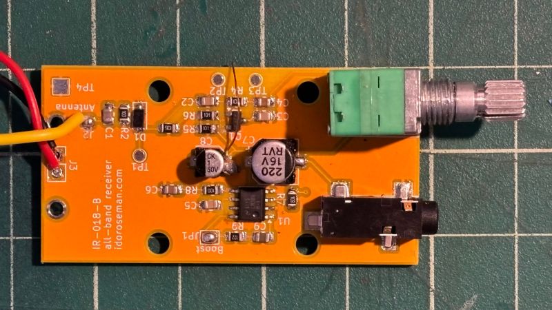
There are many ways to build a radio receiver, but most have a few things in common, such as oscillators, tuned circuits, detectors, mixers, and amplifiers. Put those together in the right order and you’ve got a receiver ready to tune in whatever you want to listen to. But if you don’t really care about tuning and want to hear everything all at once, that greatly simplifies the job and leaves you with something like this homebrew all-band receiver.

Granted, dispensing with everything but a detector and an audio amplifier will seriously limit any receiver’s capabilities. But that wasn’t really a design concern for [Ido Roseman], who was in search of a simple and unobtrusive way to monitor air traffic control conversations while flying. True, there are commercially available radios that tune the aviation bands, and there are plenty of software-defined radio (SDR) options, but air travel authorities and fellow travelers alike may take a dim view of an antenna sticking out of a pocket.

So [Ido] did a little digging and found a dead-simple circuit that can receive signals from the medium-wave bands up into the VHF range without regard for modulation. The basic circuit is a Schottky diode detector between an antenna and a high-gain audio amplifier driving high-impedance headphones; [Ido] built a variation that also has an LM386 amplifier stage to allow the use of regular earbuds, which along with a simple 3D-printed case aids in the receiver’s stealth.

With only a short piece of wire as an antenna, reception is limited to nearby powerful transmitters, but that makes it suitable for getting at least the pilot side of ATC conversations. It works surprisingly well — [Ido] included a few clips that are perfectly understandable, even if the receiver also captured things like cell phones chirping and what sounds like random sferics. It seems like a fun circuit to play with, although with our luck we’d probably not try to take it on a plane.

Making Sure Your Patch Cables Are Ready for RF Work

How do you know that your patch cables are good? For simple jumper wires, a multimeter is about all you need to know for sure. But things can get weird in the RF world, in which case you might want to keep these coaxial patch cable testing tips in mind.

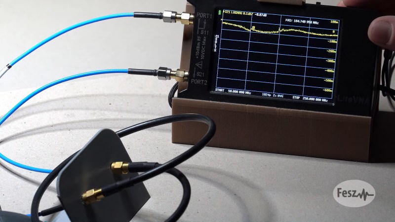
Of course, no matter how high the frequency, the basics still apply, and [FesZ] points out in the video below that you can still get a lot of mileage out of the Mark 1 eyeball and a simple DMM. Visual inspection of the cable and terminations can reveal a lot, as can continuity measurements on both the inner and outer conductors. Checking for shorts between conductors is important, too. But just because the cable reads good at DC doesn’t mean that problems aren’t still lurking. That’s when [FesZ] recommends breaking out a vector network analyzer like the NanoVNA. This tool will allow you to measure the cable’s attenuation and return loss parameters across the frequency range over which the cable will be used.

For stubborn problems, or just for funsies, there’s also time-domain reflectometry, which can be done with a pulse generator and an oscilloscope to characterize impedance discontinuities in the cable. We’ve covered simple TDR measurement techniques before, but [FesZ] showed a neat trick called time-domain transformation, which uses VNA data to visualize the impedance profile of the whole cable assembly, including its terminations.

Rethinking Your Jellybean Op Amps

Are your jellybeans getting stale? [lcamtuf] thinks so, and his guide to choosing op-amps makes a good case for rethinking what parts you should keep in stock.

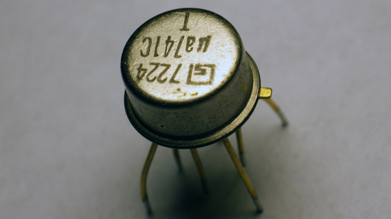
For readers of a certain vintage, the term “operational amplifier” is almost synonymous with the LM741 or LM324, and with good reason. This is despite the limitations these chips have, including the need for bipolar power supplies at relatively high voltages and the need to limit the input voltage range lest clipping and distortion occur. These chips have appeared in countless designs over the nearly 60 years that they’ve been available, and the Internet is littered with examples of circuits using them.

For [lcamtuf], the abundance of designs for these dated chips is exactly the problem, as it leads to a “copy-paste” design culture despite the far more capable and modern op-amps that are readily available. His list of preferred jellybeans includes the OPA2323, favored thanks to its lower single-supply voltage range, rail-to-rail input and output, and decent output current. The article also discussed the pros and cons of FET input, frequency response and slew rate, and the relative unimportance of internal noise, pointing out that most modern op-amps will probably be the least thermally noisy part in your circuit.

None of this is to take away from how important the 741 and other early op-amps were, of course. They are venerable chips that still have their place, and we expect they’ll be showing up in designs for many decades to come. This is just food for thought, and [lcamtuf] makes a good case for rethinking your analog designs while cluing us in on what really matters when choosing an op-amp.

Hackaday Links: January 5, 2025

Hackaday Links Column Banner

Good news this week from the Sun’s far side as the Parker Solar Probe checked in after its speedrun through our star’s corona. Parker became the fastest human-made object ever — aside from the manhole cover, of course — as it fell into the Sun’s gravity well on Christmas Eve to pass within 6.1 million kilometers of the surface, in an attempt to study the extremely dynamic environment of the solar atmosphere. Similar to how manned spacecraft returning to Earth are blacked out from radio communications, the plasma soup Parker flew through meant everything it would do during the pass had to be autonomous, and we wouldn’t know how it went until the probe cleared the high-energy zone. The probe pinged Earth with a quick “I’m OK” message on December 26, and checked in with the Deep Space Network as scheduled on January 1, dumping telemetry data that indicated the spacecraft not only survived its brush with the corona but that every instrument performed as expected during the pass. The scientific data from the instruments won’t be downloaded until the probe is in a little better position, and then Parker will get to do the whole thing again twice more in 2025.

Good news too for Apple users, some of whom stand to get a cool $100 as part of a settlement into allegations that Siri-enabled devices “unintentionally” recorded conversations. The $95 million agreement settles a lawsuit brought by users who were shocked — SHOCKED! — to see ads related to esoteric subjects they had recently discussed, apparently independently of uttering the “Hey, Siri” wake phrase. Apple seems to acknowledge that some recordings were made without the wake word, characterizing them as “unintentional” and disputing the plaintiffs’ claims that the recordings were passed to third parties for targeted advertising. The settlement, which may be certified in February, would award the princely sum of $20 to claimants for each Apple device they owned over a ten-year period, up to five devices total.

In related news, Apple is also getting some attention for apparently opting users into its Enhanced Visual Search system. The feature is intended to make it easier to classify and search your photos based on well-known landmarks or points of interest, so if you take a selfie in front of the Eiffel Tower or Grand Canyon, it’ll recognize those features visually and record the fact. It does so by running your snapshots through a local AI algorithm and then encrypting the portion of the image it thinks contains the landmark. The encrypted portion of the image then goes to the cloud for analysis, apparently without getting decrypted, and the suggested location goes back to your device in encrypted form. It’s possible to turn the feature off, but you have to know it’s there in the first place, which we imagine not a lot of Apple users do. While there’s no sign that this new feature leaks any user data, there are a lot of moving pieces that sure seem ripe for exploitation, given enough time.

Are you as sick of counting the numbers of bridges or traffic lights in potato-vision images or trying to figure out if that one square has a few pixels of the rear-view mirror of a motorcycle to prove you’re human? We sure are, and while we’d love to see CAPTCHAs go the way of the dodo, they’re probably here to stay. So, why not have fun with the concept and play a round of DOOM on nightmare mode to prove your non-robotness? That was Guillermo Rauch’s idea, and we have to say it’s pretty cool. You’ve got to kill three monsters to solve the puzzle, and we found it pretty difficult, in part because we’re more used to the WASD layout than using the arrow keys for player movement. Just watch out if you give it a try with headphones on — it’s pretty loud.

And finally, if you feel like your life is missing in-depth knowledge of the inner workings of a Boeing 777’s auxiliary power unit, we’ve got good news for you. We stumbled across this playlist of excellent animations that shows every nook and cranny of the APU, and how it operates. For the uninitiated, the APU is basically a gas turbine engine that lives in the tail of jetliners and provides electrical and pneumatic power whenever the main engines aren’t running. It sounds simple, but there’s so much engineering packed into the APU and the way it integrates into the aircraft systems. We’ve always known that jets have a lot of redundancy built into them, but this series really brought that home to us. Enjoy!

And finally finally, we generally don’t like to plug the Hack Chat here in this space, but we thought we’d make an exception since we’re kicking off the 2025 series in a big way with Eben Upton! The co-founder and CEO of Raspberry Pi will stop by the Hack Chat on January 15 at noon Pacific time, and we just want to get the word out as soon as possible. Hope to see you there!

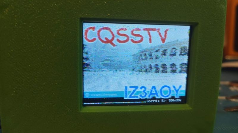
Pi Pico Makes SSTV Reception a Snap

There’s a paradox in amateur radio: after all the time and effort spent getting a license and all the expense of getting some gear together, some new hams suddenly find that they don’t have a lot to talk about when they get in front of the mic. While that can be awkward, it’s not a deal-breaker by any means, especially when this Pi Pico SSTV decoder makes it cheap and easy to get into slow-scan television.

There’s not much to [Jon Dawson]’s SSTV decoder. Audio from a single-sideband receiver goes through a biasing network and into the Pico’s A/D input. The decoder can handle both Martin and Scottie SSTV protocols, with results displayed on a TFT LCD screen. The magic is in the software, of course, and [Jon] provides a good explanation of the algorithms he used, as well as some of the challenges he faced, such as reliably detecting which protocol is being used. He also implemented correction for “slant,” which occurs when the transmitter sample rate drifts relative to the receiver. Fixing that requires measuring the time it took to transmit each line and adjusting the timing of the decoder to match. The results are dramatic, and it clears up one of the main sources of SSTV artifacts.

We think this is a great build, and simple enough that anyone can try it. The best part is that since it’s receive-only, it doesn’t require a license, although [Jon] says he’s working on an encoder and transmitter too. We’re looking forward to that, but in the meantime, you might just be able to use this to capture some space memes.

Thanks to [CJay] for the tip.

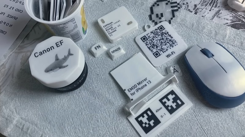
Dress Up Your 3D Prints with Toner-Transfer Labels

We’ve always found the various methods for adding text and graphics to 3D prints somewhat underwhelming. Embossed or debossed characters are fuzzy, at best, and multi-color printers always seem to bleed one color into the next. Still, the need for labels and logos is common enough that it’s worth exploring other methods, such as this easy toner transfer trick.

Home PCB makers will probably find the method [Squalius] describes in the video below very familiar, and with good reason. We’ve seen toner transfer used to mask PCBs before etching, and the basic process here is very similar. It starts with printing the desired graphics on regular paper using a laser printer; don’t forget to mirror the print. The printed surface is scuffed up a bit, carefully cleaned, and coated with a thick layer of liquid acrylic medium, of the kind used in paint pouring. The mirrored print is carefully laid on the acrylic, toner-side down, and more medium is brushed on the back of the paper. After the print dries, the paper is removed with a little water and some gentle friction, leaving the toner behind. A coat of polyurethane protects the artwork reasonably well.

[Squalius] has tested the method with PLA and PETG and reports good results. The text is clear and sharp, and even fine text and dithered graphics look pretty good. Durability could be better, and [Squalius] is looking for alternative products that might work better for high-wear applications. It looks like it works best on lightly textured surfaces, too, as opposed to surfaces with layer lines. We’d love to see if color laser prints work, too; [Squalius] says that’s in the works, and we’ve seen examples before that are reason for optimism.

Thanks to [greg_bear] for the tip.

Lowering Your Noise Floor, the Easy Way

If there’s anything more annoying to an amateur radio operator than noise, we’re not sure what it could be. We’re talking about radio frequency noise, of course, the random broadband emissions that threaten to make it almost impossible to work the bands and pick out weak signals. This man-made interference is known as “QRM” in ham parlance, and it has become almost intolerable of late, as poorly engineered switch-mode power supplies have become more common.

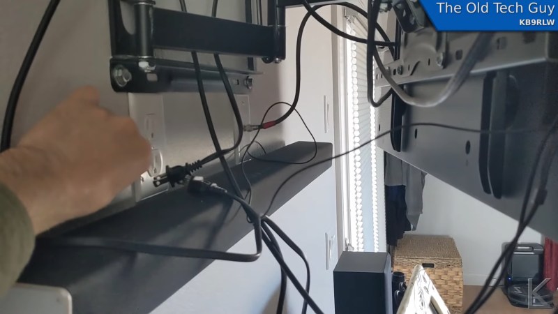
But hams love a technical challenge, so when a nasty case of QRM raised its ugly head, [Kevin Loughlin (KB9RLW)] fought back. With an unacceptable noise floor of S8, he went on a search for the guilty party, and in the simplest way possible — he started flipping circuit breakers. Sure, he could have pulled out something fancier like a TinySA spectrum analyzer, but with his HF rig on and blasting white noise, it was far easier to just work through the circuits one by one to narrow the source down. His noise problem went away with the living room breaker, which led to pulling plugs one by one until he located the culprit: a Roomba vacuum’s charging station.

Yes, this is a simple trick, but one that’s worth remembering as at least a first pass when QRM problems creep up. It probably won’t help if the source is coming from a neighbor’s house, but it’s a least worth a shot before going to more involved steps. As for remediation, [Kevin] opts to just unplug the Roomba when he wants to work the bands, but if you find that something like an Ethernet cable is causing your QRM issue, you might have to try different measures.

Ball Nut Modification Charts a Middle Course Between Building and Buying

A lot of the projects we feature here on Hackaday engender the classic “build versus buy” argument. We’ve always been puzzled by that; if anyone can appreciate the sheer joy of making something rather than buying it, it should be our readers. But there’s something to be said for buying the stuff you can buy and concentrating your effort on the bespoke aspects of the project. It’s perhaps not as exciting, but needs must, oftentimes.

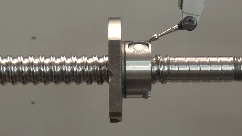
Let’s not forget there’s a third way though, which [Andy] explores with this ball nut modification project. Keen-eyed readers will recall [Andy]’s recent scratch-built ball screw build, in service of some top-secret, hush-hush project related to world domination and total subjugation of humanity. His homebrew efforts in this regard were a great lesson in how to machine a complex mechanism to work in a constrained space. Still, it left folks wondering why he’d go to all the trouble when he could have just trimmed an off-the-shelf part down to size. So, he decided to give that a try.

After securing a ball nut of the proper pitch and diameter, [Andy] looked for ways to shorten it without ruining it. Unfortunately, ball nuts are usually made of hardened steel, which tends to make the usual subtractive methods difficult. But when all else fails, you pull out the metal shop problem solver: the angle grinder. That had the benefit of shortening the nut while simultaneously annealing the steel around the cut, making it possible to face in the lathe. [Andy] put this happy accident to use twice in the build, and it’s a tip we’ll be filing away for a rainy day.

The whole modification process is presented in the video below, which includes testing the modified ball nut. It turned out pretty well, at least in terms of axial backlash. There are compromises, of course, but far fewer than we expected when the sparks started flying from that precision-machined ball nut.

A Die-Level Look at the Pentium FDIV Bug

The early 1990s were an interesting time in the PC world, mainly because PCs were entering the zeitgeist for the first time. This was fueled in part by companies like Intel and AMD going head-to-head in the marketplace with massive ad campaigns to build brand recognition; remember “Intel Inside”?

In 1993, Intel was making some headway in that regard. The splashy launch of their new Pentium chip in 1993 was a huge event. Unfortunately an esoteric bug in the floating-point division module came to the public’s attention. [Ken Shirriff]’s excellent account of that kerfuffle goes into great detail about the discovery of the bug. The issue was discovered by [Dr. Thomas R. Nicely] as he searched for prime numbers. It’s a bit of an understatement to say this bug created a mess for Intel. The really interesting stuff is how the so-called FDIV bug, named after the floating-point division instruction affected, was actually executed in silicon.

We won’t presume to explain it better than [Professor Ken] does, but the gist is that floating-point division in the Pentium relied on a lookup table implemented in a programmable logic array on the chip. The bug was caused by five missing table entries, and [Ken] was able to find the corresponding PLA defects on a decapped Pentium. What’s more, his analysis suggests that Intel’s characterization of the bug as a transcription error is a bit misleading; the pattern of the missing entries in the lookup table is more consistent with a mathematical error in the program that generated the table.

The Pentium bug was a big deal at the time, and in some ways a master class on how not to handle a complex technical problem. To be fair, this was the first time something like this had happened on a global scale, so Intel didn’t really have a playbook to go by. [Ken]’s account of the bug and the dustup surrounding it is first-rate, and if you ever wanted to really understand how floating-point math works in silicon, this is one article you won’t want to miss.

The Business Card of DOOM

This account of running DOOM on a PCB business card isn’t really about serving the “Will it DOOM?” meme of getting the classic game to run on improbable hardware. Rather, this project has more to do with getting it done right and leveraging work that’s already been done.

We’ll explain. You may recall [rsheldiii]’s previous DOOM keycap build, which was quite an accomplishment for someone who doesn’t fancy himself a hardware hacker. But he made a fair number of compromises to pull that build off, and rather than letting those mistakes propagate, he decided to build a more general platform to serve as a jumping-off point for the DOOM building community. The card is centered on the RP2040, which keeps things pretty simple. The card has a tiny LCD screen along with USB jacks for power and a keyboard, so you can actually play the game. It also has GPIO lines brought out to pads on the edge of the board, in case you want to do something other than play the game, which is shown in the brief video below.

Pretty standard stuff, right? Perhaps, but where this project stands out for us is that it stresses the importance of relying on reference circuits. We’ve all seen projects that have been derided for pulling the example circuit from the datasheet, but as [rsheldiii] points out, that seems a little wrongheaded. Component manufacturers put a lot of effort into those circuits, and they don’t do it out of the goodness of their hearts. Yes, they want to make it easier for engineers to choose their parts, but in doing so they’ve done a lot of the work for you. Capitalizing on that work wherever possible only makes sense, and in this case the results were perfect for the task at hand.

A Low-Cost Spectrometer Uses Discrete LEDs and Math

A spectrometer is a pretty common lab instrument, useful for determining the absorbance of a sample across a spectrum of light. The standard design is simple; a prism or diffraction grating to break up a light source into a spectrum and a detector to measure light intensity. Shine the light through your sample, scan through the spectrum, and graph the results. Pretty easy.

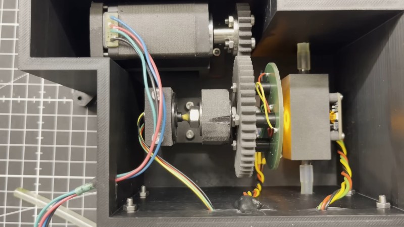
That’s not the only way to do it, though, as [Markus Bindhammer] shows with this proof-of-concept UV/visible spectrometer. Rather than a single light source, [Marb] uses six discrete LEDs, each with a different wavelength. The almost-a-rainbow’s-worth of LEDs are mounted on circular PCB, which is mounted to a stepper motor through a gear train. This allows the instrument to scan through all six colors, shining each on the sample one at a time. On the other side of the flow-through sample cuvette is an AS7341 10-channel color sensor, which can measure almost the entire spectrum from UV to IR.

The one place where this design seems iffy is that the light source spectrum isn’t continuous, as it would be in a more traditional design. But [Marb] has an answer for that; after gathering data at each wavelength, he applies a cubic spline interpolation to derive the spectrum. It’s demonstrated in the video below using chlorophyll extracted from spinach leaves, and it seems to generate a reasonable spectrum. We suppose this might miss a narrow absorbance spike, but perhaps this could be mitigated by adding a few more LEDs to the color wheel.


Blast Away the Flux — With Brake Cleaner?

Can you use brake cleaner for flux removal on PCBs? According to [Half Burnt Toast], yes you can. But should you? Well, that’s another matter.

In our experience, flux removal seems to be far more difficult than it should be. We’ve seen plenty of examples of a tiny drop of isopropyl alcohol and a bit of light agitation with a cotton swab being more than enough to loosen up even the nastiest baked-on flux. If we do the same thing, all we get is a gummy mess embedded with cotton fibers smeared all over the board. We might be doing something wrong, or perhaps using the wrong flux, but every time we get those results, we have to admit toying with the idea of more extreme measures.

The LED bar graphs were not a fan of the brake cleaner.

[Toast] went there, busting out a fresh can of brake cleaner and hosing down some of the crustier examples in his collection. The heady dry-cleaner aroma of perchloroethylene was soon in the air, and the powerful solvent along with the high-pressure aerosol blast seemed to work wonders on flux. The board substrate, the resist layer, and the silkscreen all seemed unaffected by the solvent, and the components were left mostly intact; one LED bar graph display did a little melty, though.

So it works, but you might want to think twice about it. The chlorinated formula he used for these tests is pretty strong stuff, and isn’t even available in a lot of places. Ironically, the more environmentally friendly stuff seems like it would be even worse, loaded as it is with acetone and toluene. Whichever formula you choose, proceed with caution and use the appropriate PPE.

What even is flux, and what makes it so hard to clean? Making your own might provide some answers.

A LoRa Rain Gauge from the Ground Up

It’s a fair bet that most of us have a ton of wireless doo-dads around the house, from garage door remotes to wireless thermometers. Each of these gadgets seems to have its own idea about how to encode data and transmit it, all those dedicated receivers seem wasteful. Wouldn’t it be great to use existing RF infrastructure to connect your wireless stuff?

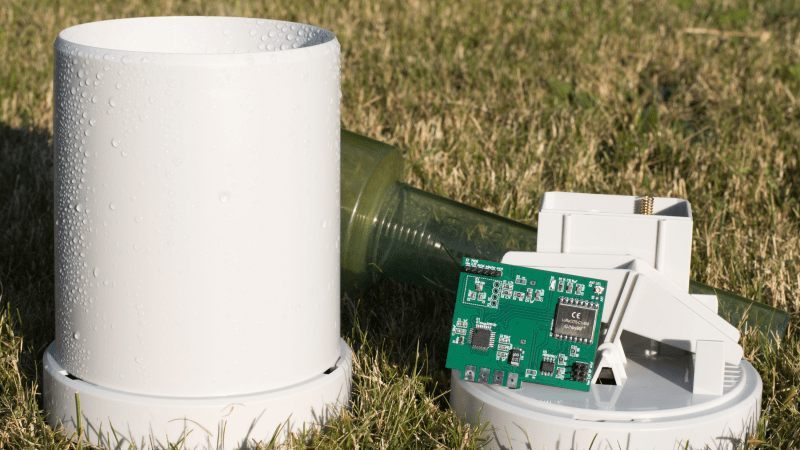
[Malte Pöggel] thinks so, and this LoRa rain gauge is the result. The build starts with a commercially available rain transmitter, easily found on the cheap as an accessory for a wireless weather station and already equipped with an ISM band transmitter. The rain-collection funnel and tipping-bucket mechanism were perfectly usable, and the space vacated by the existing circuit boards left plenty of room to play, not to mention a perfectly usable battery compartment. [Malte] used an ATmega328P microcontroller to count the tipping of the bucket, either through the original reed switch or via Hall Effect or magnetoresistive sensors. An RFM95W LoRa module takes care of connecting into [Malte]’s LoRaWAN gateway, and there’s an option to add a barometric pressure and temperature sensor, either by adding the BMP280 chip directly to the board or by adding a cheap I2C module, for those who don’t relish SMD soldering.

[Malte] put a lot of work into power optimization, and it shows. A pair of AA batteries should last at least three years, and the range is up to a kilometer—far more than the original ISM connection could have managed. Sure, this could have been accomplished with a LoRa module and some jumper wires, but this looks like a fantastic way to get your feet wet in LoRa design. You could even print your own tipping bucket collector and modify the electronics if you wanted.

Hackaday Links: December 22, 2024

Hackaday Links Column Banner

Early Monday morning, while many of us will be putting the finishing touches — or just beginning, ahem — on our Christmas preparations, solar scientists will hold their collective breath as they wait for word from the Parker Solar Probe’s record-setting passage through the sun’s atmosphere. The probe, which has been in a highly elliptical solar orbit since its 2018 launch, has been getting occasional gravitational nudges by close encounters with Venus. This has moved the perihelion ever closer to the sun’s surface, and on Monday morning it will make its closest approach yet, a mere 6.1 million kilometers from the roiling photosphere. That will put it inside the corona, the sun’s extremely energetic atmosphere, which we normally only see during total eclipses. Traveling at almost 700,000 kilometers per hour, it won’t be there very long, and it’ll be doing everything it needs to do autonomously since the high-energy plasma of the corona and the eight-light-minute distance makes remote control impossible. It’ll be a few days before communications are re-established and the data downloaded, which will make a nice present for the solar science community to unwrap.

While Parker has been in a similar position on previous orbits and even managed a fortuitous transit of a coronal mass ejection, this pass will be closer and faster than any previous approach. It’s the speed that really grabs our attention, though, as Parker will be traveling at a small but significant fraction of the speed of light for a bit. That makes us wonder if there was any need for mission planners to allow for relativistic effects. We’d imagine so; satellite navigation systems need to take relativity into account to work, and they don’t move anywhere near as fast as Parker. Time will be running slower for Parker at those speeds, and it sure seems like that could muck things up, especially regarding autonomous operation.

Ever since the seminal work of Cameron, Hamilton, Schwarzenegger, et al, it has been taken as canon that the end of humanity will come about when the moral equivalent of SkyNet becomes self-aware and launches all the missiles at once to blot us out with a few minutes of thermonuclear fire. But it looks like AI might be trying to raise an army of grumpy teenagers if this lawsuit over violence-inciting chatbots is any indication. The federal product liability lawsuit targets Character.AI, an outfit that creates LLM-powered chatbots for kids, for allegedly telling kids to do some pretty sketchy stuff. You can read the details in the story, but suffice it to say that one of the chatbots was none too pleased with someone’s parents for imposing screen time rules and hinted rather strongly about how the child should deal with them. The chat logs of that interaction and others that are part of the suit are pretty dark, but probably no darker than the advice that most teenagers would get online from their carbon-based friends. That’s the thing about chatbots; when an LLM is trained with online interactions, you pretty much know what’s going to come out.

In today’s “Who could have seen that coming?” segment, we have a story about how drivers are hacked by digital license plates and are keen to avoid tolls and tickets. The exploit for one specific brand of plate, Reviver, and while it does require physical access to the plates, it doesn’t take much more than the standard reverse engineering tools and skills to pull off. Once the plates are jailbroken — an ironic term given that license plate manufacturing has historically been a prison industry — the displayed numbers can be changed at will with a smartphone app. The worst part about this is that the vulnerability is baked right into the silicon, so there’s nothing to be patched; the plates would have to be recalled, and different hardware would need to be reissued. We’ve been skeptical about the need for these plates from the beginning and questioned why anyone would pay extra for them (last item). But maybe the ability to dump your traffic cam violations into someone else’s lap is worth the extra $20 a month.

And finally, this local news story from Great Falls, Montana, is a timely reminder of how machine tools can mess up your life if you let them. Machinist Butch Olson was alone at work in his machine shop back on December 6 when the sleeve of his jacket got caught in a lathe. The powerful machine pulled his arm in and threatened to turn him to a bloody pulp, but somehow, he managed to brace himself against the bed. He fought the lathe for 20 whole minutes before the motor finally gave out, which let him disentangle himself and get some help. He ended up with a broken back, four fractured ribs, and an arm that looks “like hamburger” according to his sister. That’s a high price to pay, but at least Butch gets to brag that he fought a lathe and won.

❌