Vista de Lectura

Hay nuevos artículos disponibles. Pincha para refrescar la página.

Homebrew Retro Console Runs On PIC32

[Chad Burrow] decided to take on a noble task—building a “retro” style computer and video game console. Only, this one is built using somewhat modern hardware—relying on the grunt of the PIC32MZ2048EFH144 to get the job done. Meet the Acolyte Hand PIC’d 32.

It’s name might be a mouthful, but that chip can pull off some great feats! With a clock speed of 200 MHz, it’s not  short on processing power, though RAM and flash storage are somewhat limited at just 512 KB and 2MB respectively. [Chad] was able to leverage those constraints to get a VGA output working at a resolutions up to 800 x 600, with up to 65,000 colors—though 256 colors is more practical due to memory concerns. The Acolyte Hand also rocks two 8-bit audio channels. It has a pair of Genesis-compatible controller ports as well as PS/2 and USB for keyboards and mice, along with more modern Xbox 360 controllers.

[Chad] cooked up some software to put it through its paces, too. It’s got a Tetris clone on board, and can also run Game Boy games at full speed via the Peanut-GB emulator. That provides for a pretty rich game library, though [Chad] notes he plans to develop more native video games for his system to demo at his local college. Design files are on Github for the curious.

This project is a great example of just how powerful modern microcontrollers have become. Once upon a time, just driving a simple black-and-white graphical LCD might have taken some real effort, but today, there are pixels and clock cycles to spare in projects like these. Truly a wonderous world we live in!
Electromechanical 7-Segment Display Is High Contrast Brilliance

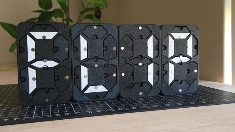
The seven-segment display is most well known in LED form, but the concept isn’t tied to that format. You can build a seven-segment display out of moving parts, too. [tin-foil-hat] has achieved just that with a remarkably elegant design.

As you might expect, the build relies heavily on 3D-printed components—produced in white and black plastic to create a high-contrast display. It’s a simple choice that makes the display easy to read in a wide variety of lighting conditions, and far less fussy than toying with LEDs and diffusers and all that.

Actuation of each display segment is achieved electromagnetically. Effectively, each segment behaves like a flip dot, with the orientation controlled by energizing one of two electromagnets per segment. Controlling the electromagnets is an ESP32, which is hooked up to the various segments via a Darlington transistor array, with multiplexing used to minimize the number of IO pins required. A shift register was also employed to let the microcontroller easily drive four of these electromechanical digits.

It’s a simple build, well explained—and the final result is aesthetically pleasing. We’ve seen a few builds along these lines before, albeit using altogether different techniques. Lots of different techniques, in fact! Video after the break.

[Thanks to Archivort for the tip!]

Using Audio Hardware To Drive Neopixels Super Fast

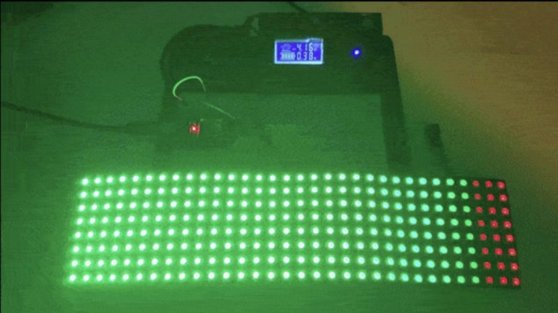
Here’s the thing about running large strings of Neopixels—also known as WS2812 addressable LEDs. You need to truck out a ton of data, and fast. There are a dozen different libraries out there to drive them already, but [Zorxx] decided to strike out with a new technique—using I2S hardware to get the job done. 

Fast!

Microcontrollers traditionally use I2S interfaces to output digital audio. However, I2s also just happens to be perfect for driving tons of addressable LEDs. At the lowest level, I2S hardware is really just flipping a serial data line really fast with a clock line and a word select line for good measure. If, instead of sound, you pipe a data stream for addressable LEDs to the I2S hardware, it will clock that data out just the same!

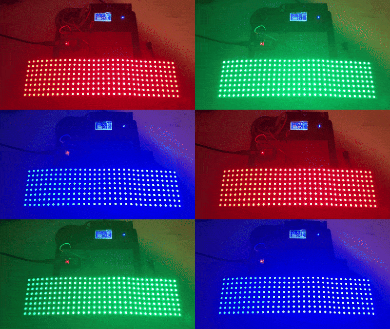
[Zorxx] figured that at with an ESP32 trucking out I2S data at a rate of 2.6 megabits per second on the ESP32,  it would be possible to update a string of 256 pixels in just 7.3 milliseconds. In other words, you could have a 16 by 16 grid updating at over 130 frames per second. Step up to 512 LEDs, and you can still run at almost 70 fps.

There’s some tricks to pulling this off, but it’s nothing you can’t figure out just by looking at the spec sheets for the WS2812B and the ESP32. Or, indeed, [Zorxx’s] helpful Github page. We’ve featured some other unorthodox methods of driving these LEDs before, too! Meanwhile, if you’ve got your own ideas on how to datablast at ever greater speeds, don’t hesitate to let us know!

Camera Slider Uses Repositionable Rail To Do Rotational Moves

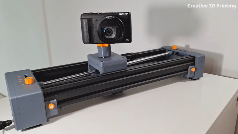
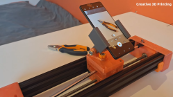
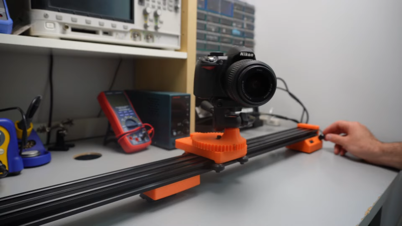
You can buy motorized camera sliders off-the-shelf, but they’re pretty costly. Alternatively, you can make one yourself, and it’s not even that hard if you’re kitted out with a 3D printer. [Creative 3D Printing] did just that with a nifty design that adds rotation into the mix. Check it out in the video below.

Why should a camera get all the fun? Try your phone.

The basic slider is built out of 3D-printed components and some good old aluminum extrusion. A small 12-volt motor trucks the camera cart back and forth using a leadscrew. It’s torquey enough and slow enough that there isn’t much need for more advanced control—the motor just does the job. There’s also a limit switch set up to trigger a neat auto-reverse function.

The neat part, though, is the rotational mechanism. A smooth steel rod is attached to the slider’s housing, which can be set up in a straight line or aligned diagonally if desired. In the latter case, it rotates the mounting on the camera cart via a crank, panning the camera as it moves along the slider’s trajectory.

It’s a mechanically sophisticated design and quite unlike most of the camera sliders we feature around these parts.

E-Paper Anniversary Counter Is A Charming Gift With Minimal Power Draw

[Lonyelon] wanted to build an anniversary gift for his girlfriend. He decided to say it with e-Paper, a wise choice given its persistence and longevity.

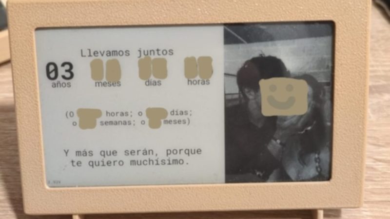
The project is an anniversary calendar. It displays a counter of the total time the couple has been together, measured in years, months, days, and hours—so it’s remarkably precise. [Lonyelon] also programmed it to display additional counters to create plenty of additional fun anniversaries—the couple can celebrate milestones like their 1000th day together, for example. It also cycles through a range of cute messages and displays photos of the couple together.

The code is on Github for the curious. The build is based around a LilyGO e-Paper display with an onboard ESP32 microcontroller. [Lonyelon] paired this with a 2,500 mAh battery. It lasts for ages because the device is programmed to update only every 20 minutes, spending the rest of its time in deep sleep. Since it’s an e-Paper display, it uses zero power when it’s not being updated, so it’s the perfect technology for this application.

It’s a simple project that comes from the heart—the core of any beautiful gift. In fact, some of the coolest projects we feature were built as gifts for romantic partners, family members, or even our fellow hackers. If you’ve been cooking up your own neat build, please let us know on the tipsline!

DIY Camera Slider Moves And Rotates For Slick Shots

Camera sliders are a popular project for makers—especially those who document their projects on video. They’re fun and accessible to build, and they can really create some beautiful shots. [Lechnology] set about to follow in this fine tradition and built a rather capable example of his own. Check it out in the video below.

The slider relies on V-slot rails, perhaps most familiar for their heavy use in modern 3D printers. The rails are paired with a 3D-printed camera carriage, which runs on smooth rubber rollers. A chunky stepper motor provides drive via a toothed belt. Trinamic motor controllers were chosen for their step interpolation feature, making the motion much smoother.

The slider doesn’t just move linearly, either. It can rotate the camera, too, since it has an additional motor in the carriage itself. In a nice retro touch, the wires for this motor are run with an old coiled telephone cable. It’s perfect for the job since it easily extends and retracts with the slider’s motion. Controlling everything is an Arduino, with speed and rotational modes set via a tiny screen and a rotary encoder control.

It’s a very complete build, and it performs well too. The video it produces is deliciously smooth. We’ve featured some other great camera sliders over the years, too. If you want to dig into Trinamic drivers, we can get you started.

3D Printed Forklift Is A Cute Desk Toy

Many of us grew up with dreams of piloting a forklift one day. Sadly, most warehouses take a dim view of horseplay with these machines, so few of us get to live out those fantasies. Playing with this desk-sized RC model from [ProfessorBoots] is probably a safer way to get those kicks instead. You can check it out in the video below.

The 3D-printed body of the forklift is the first thing you see. It’s great quality, and it instantly puts you in mind of the real thing. The build is true to the dynamics of a real forklift, too, with proper rear steering. Inside, there’s a custom circuit board hosting an ESP32 that serves as the brain of the operation. Its onboard wireless hardware allows remote control of the forklift via a smartphone app, PS4 controller, or many other options. It controls the drive motors and steering servo, along with another motor driving a threaded rod to move the forks up and down. The whole thing is powered by two Fenix 16340 batteries—small lithium-ion cells that can be recharged with an integral micro USB port.

The project video is very thorough about the design and build. It’s worth watching just to understand the specifics of how forklifts actually raise their forks up and down. It’s good stuff.

This forklift is just the latest RC build from [ProfessorBoots]. He’s done great work in this space before, like this charming skid steer and incredibly complex crane.

Vintage Audio Amp Gets LED Lighting Upgrade

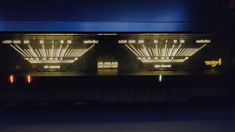
Vintage hi-fi gear can be very attractive, particularly compared to modern stuff. However, when this stuff starts getting into its third or fourth decade after production, things start to wear out. Chief among them—the little incandescent bulbs that light up the dials with such a beautiful glow. [Piffpaffpoltrie] was suffering just this problem on an old Technics amp, and decided to go for a more modern upgrade.

Replacing the original bulb with a like unit was undesirable—even if many last for decades, [Piffpaffpoltrie] didn’t want to have to tackle this job again in the future. Instead, an LED swap was the order of the day. A short strip of warm-white LEDs seemed to be the perfect solution, with three LEDs in series being just about right for the 11-volt supply used for the original bulbs. The only problem was that the stereo supplied the bulbs with AC, not DC. Thus, a quick bridge rectifier circuit was thrown in, along with some series resistors. This wrangled the voltage into a straighter line and delivered the right voltage level to drive the LEDs nicely and smoothly.

The result is a nicely-illuminated set of power meters on this vintage Technics amp. We’ve seen some neat LED swaps in the past, too, including this tricky motorcycle lamp upgrade. Meanwhile, if you’re slogging it out to bring your vintage gear more up to date, consider dropping us a note on the tipsline.

An LCD, Touch Sensor, USB-C, And A Microcontroller for a Buck

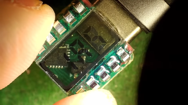
[CNLohr] has been tinkering with some fun parts of late. He’d found out that ordinary LCD screens could be used as simple touch sensors, and he had to try it for himself. He ended up building a little doohickey that combined USB C, an LCD display, and a touch interface, all for under a buck. You can check out the video below.

The key to this build was the CH32V003 CPU. It’s a RISC-V microcontroller that runs at a healthy 48 MHz, and it costs just 10 cents in reasonable quantities. A PCB etched to mate with a USB C cable eliminates the need for a connector.

[CNLohr] then gave the board a three-digit 7-segment LCD display from Aliexpress, which can be had for around 21 cents if you buy 100 or more. He then figured out how to drive the LCDs with a nifty trick that let the microcontroller use the display as a crude touch sensor. All in all, the total bill of materials for one of these things comes out somewhere under a dollar in quantity.

It’s mostly a random assemblage of tech glued together for a demo, but it’s a fun project. It’s worth checking out even if it’s just to learn how to create an integral USB C port on your own PCBs. The way it’s achieved with the etched contacts and milled-out tabs is pure elegance. Files are on Github for the curious.

We’ve featured a ton of [CNLohr’s] work over the years; the clear keytar was a glowing highlight, as were his early discoveries in the depths of the ESP8266.

Building A Custom Swiss Army Knife

The Swiss Army knife is the most well-known multitool, combining a bunch of functionality into a compact package. [Jeff Gough] decided to build a custom example featuring a selection of his favorite tools.

He documents the build in a video series on YouTube (see below). [Jeff] decided to take on the project as a gift for his mother after she’d mentioned she’d wanted a Swiss Army-style knife with a horse’s hoof tool and finished in the classic shade of British Racing Green.

[Jeff] starts by disassembling an existing knife, taking care not to damage it in the process. He then makes and installs multiple custom tools, including the aforementioned horse hoof tool and a RADAR/NKS key for opening disabled toilets in the UK. He even crafts a bespoke Philips head screwdriver, too. Finally, he assembles everything back together and gives the build a beautiful green finish.

A Swiss Army knife can be a neat gift, but it’s even nicer when it’s got a personal touch like this one. We’ve featured some other nifty multitools before, too. Not all Swiss Army knives actually contain a, you know, knife. No kidding.

3D Printing a Big LEGO Christmas Tree

LEGO make lots of neat floral arrangements these days, and even little Christmas trees, too. While they’re fun to build out of tiny little blocks, they’re a little small for use as your main Christmas tree. Sadly, a bigger version simply doesn’t exist in the LEGO catalog, so if that’s your desire, you’ll have to build your own—as [Ruth] and [Ellis] did!

The concept behind the build is as you’d expect. The duo effectively just 3D printed giant versions of LEGO pieces, with which they then assembled a large Christmas tree. It sounds very straightforward, but scaling an existing LEGO design up by six times tends to come with some complications. A tactical decision was made early on to ease proceedings—the original LEGO tree had a large brown base that would take lots of printing. This was eliminated in the hopes that it would speed the build significantly. The long plastic shafts that supported the original design were also replaced with steel shafts since printing them would have been incredibly difficult to do well.

The rest of the video demonstrates the huge amount of work that went into actually 3D printing and assembling this thing. It’s pretty great to watch, and you’ll learn a lot along the way.

We’ve seen other creators try similar projects, where they 3D print their own building blocks from scratch. It normally turns out much harder than expected! No surprise when you think about all the engineering that went into perfecting LEGO all those years ago.

Thanks to [Jonathan] for the tip!

Making a Mechanical Watch From Scratch Is Fine Work

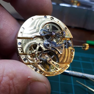
There are plenty of hard jobs out there, like founding your country’s nuclear program, or changing the timing chain on a BMW diesel. Making your own mechanical watch from scratch falls under that umbrella, too. And yet, [John Raffaelli] did just that, and prevailed!

That’s a lot of work.

Only a handful of components were purchased—[John] grabbed jewels, sapphire crystals, the strap, and the hairspring and mainspring off the shelf. Everything else, he made himself, using a fine touch, a sharp eye, and some deft work on his machine tools. If you’ve never worked at this scale before, it’s astounding to see—[John] steps through how he produced tiny pinions and balance wheels that exist at sub-fingertip scale. Even just assembling something this tiny would be a challenge, but [John] was able to craft it all from scratch and put it together into a functioning timepiece when he was done.

The final piece doesn’t just look great—we’re told it keeps good time as well. People like [John] don’t come along every day, though we do have one similar story in our deep archives from well over a decade ago. If you’re cooking up your own bespoke time pieces in your home workshop, don’t hesitate to drop your story on the tipsline!

Building a Diet Coke Button

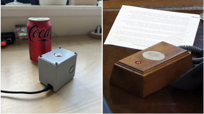
[mars91] had an interesting problem to solve—his girlfriend often requested Diet Coke, but yelling for one across the apartment was frustrating and impractical. A dedicated Diet Coke button seemed like the perfect solution, so that’s precisely what he built.

The Diet Coke Button is a relatively simple device. A small silver push-button activates an Adafruit Feather M0 to send out a signal via its RFM95 LoRa radio. That signal is picked up by the receiver device, which runs on an ESP32. It’s got an RFM95 LoRa module, which receives signals from the button and sounds an alarm to indicate the request for a Diet Coke. The ESP32 also hosts a basic website which allows Diet Coke requests to be submitted via the web, as well as general submissions of a textual nature. The latter are displayed on a small OLED display. If you’re feeling bold, you can even set up the ESP32 to be accessible from the outside Internet, with [mars91] explaining how to do so using a Cloudflare tunnel for your own protection.

The only problem is that delivering the Diet Coke is still something you have to do by hand. Perhaps a future upgrade would involve some kind of small apartment-spanning railway for the delivery of ice-cold cans to designated stations.

It’s a unique project, and one that recalls us of an interesting talk about a different type of call button.

Multimeter Gets Socket Upgrade To Use Nicer Probes

[Piffpaffpoltrie] had a problem. They found the InLine VA40R to be a perfectly usable multimeter, except for a couple of flaws. Most glaring among these were the tiny sockets for the test probes. These proved incompatible with the probes they preferred to use, so naturally, something had to be done. 

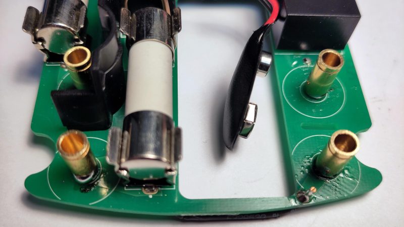
The desire was to see the multimeter work with [Piffpaffpoltrie]’s connector of choice: the 4 mm Multi Contact banana plug from Stäubli. Swiss-made, gold-plated, and highly reliable, nothing else would do. The original sockets on the multimeter were simply too small to properly accept these, so to make them work, they were machined down, drilled, tapped, and then fitted with a short M3 screw which was then soldered in place. This short length of thread then allowed the new sockets to bolt right into the PCB in place of the original sockets.

Ultimately, many would just buy a new multimeter. This hack is a fiddly and time-consuming one, but it’s kind of neat to see someone go to such lengths to customize their tools to their own satisfaction.

We don’t see a lot of multimeter hacks, because these tools usually get all the necessary features from the manufacturer. Still, the handful we’ve featured have proven most interesting. If you’re tinkering away at customizing your own test gear, don’t hesitate to drop us a line!

Old BBC Micro Gets Some Disk Help From A Raspberry Pi

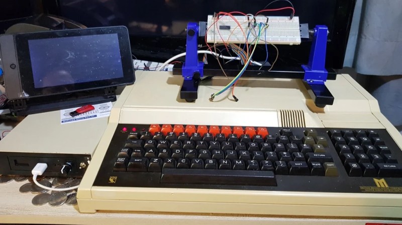
[Peter Mount] had a simple problem. He’d treated himself to a retro purchase in the form of a BBC Master 128—a faster sequel to the BBC Micro Model B. The only problem was he needed a way to get software on to it. Cue a creative hack using a Raspberry Pi Zero W.

When [Peter] received the machine, it already had a GoTek floppy emulator, which pulled disk images off a USB drive. However, he wanted an easier and quicker way to get disk images to and from the machine for development purposes. Swapping the USB drive to and from another machine seemed too tedious.

Instead, he decided to swap in a Pi Zero W for this purpose, setting it up to emulate a flash drive by following instructions from MagPi Magazine. This would allow him to use the SCP tool to copy disk images over to the Pi Zero W via its WiFi connection. Basically, the Pi Zero W was acting as a wirelessly-updated storage device hooked up to the GoTek floppy emulator.

It’s a nifty way of doing things. [Peter] could have set about creating his own floppy emulator from scratch with wireless capability included. However, there was no need. He just needed a wirelessly-accessible USB drive, and the Pi Zero W was more than happy to act in that role.

The BBC Micro is a beloved machine of many in the British Isles, and it had rather an extended family. If you’ve pulled off your own nifty hack on this classic machine, be sure to hit us up on the tipsline!

Getting Dial-Up To Work Over VOIP Isn’t Always Easy

Dial-up modems used to be the default way of accessing the Internet, but times have moved on. They’re now largely esoteric relics from a time gone by. With regular old phone lines rather hard to come by these days, [Peter Mount] decided to try getting a pair of dial-up modems working over VoIP instead.

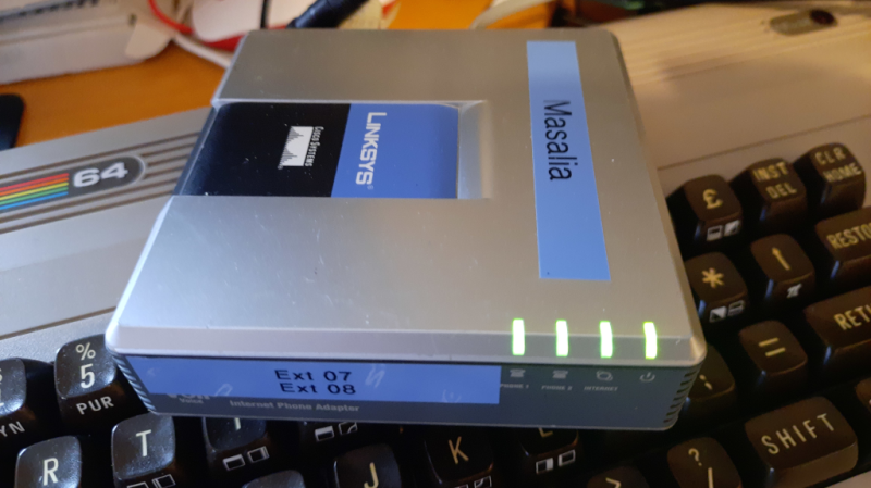
The build started with a pair of Linksys PAP2T VoIP phone adapters, which were originally designed for hooking regular phones up to VoIP systems. He paired each US Robotics modem with a PAP2T, and then hooked both into a VoIP Private Branch Exchange which he set up using 3cx on a Raspberry Pi 3B+. The Pi also acted as a server for the modems to connect to. It took a lot of fiddly configuration steps, but he found success in the end. On YouTube, he demonstrates the setup—with that glorious modem sound—communicating successfully at a rate of 9600 baud.

It’s nice to see this vintage hardware communicating in a what is effectively a simulated world created entirely within modern hardware. We’ve seen similar projects before, like this attempt to get dial-up going over Discord. If you’re doing your own odd-ball screechy communications experiments, don’t hesitate to drop us a line!

Fibonacci Clock Looks Like Beautiful Modern Art

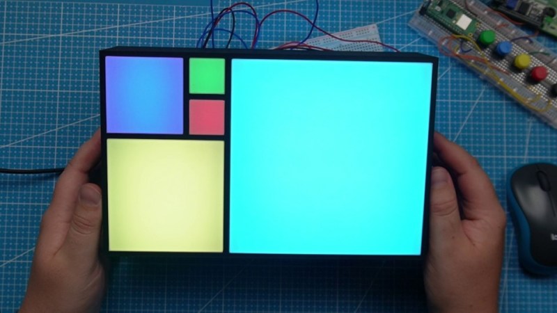
Don’t ask us why, but hackers and makers just love building clocks. Especially in the latter case, many  like to specialize in builds that don’t even look like traditional timepieces, and are difficult to read unless you know the trick behind them. [NerdCave] has brought us a pleasing example of such a thing, in the form of this gorgeous Fibonacci clock.

The build was inspired by an earlier Fibonacci clock that later became a Kickstarter project. Where that build used an Atmega328P, though, [NerdCage] landed on using a Raspberry Pi Pico W instead. The build throws the microcontroller board on a custom PCB, and sticks in inside an attractive 3D-printed enclosure. Black filmanet was used for the body, while white filament was used for the face of each square to act as a diffuser. Addressable RGB LEDs are used to illuminate the five square segments of the clock.

Obviously, you’re wondering how to read the clock. All you need to know is this. The first five numbers in the Fibonacci sequence are 1, 1, 2, 3, and 5. Each square on the clock represents one of these numbers—the side lengths of each square match these numbers. Red and green are used to represent hours and minutes, respectively, while a blue square is representing both. Basically, to get the hour, add up the values of red and blue squares, and to get the minutes, do the same with green and blue squares, but then multiply by 5. In the header image, the clock is displaying 8:55 PM… we think.

We’ve featured Fibonacci-themed clocks before, albeit ones with entirely different visual themes. Video after the break.

Learning About The Flume Water Monitor

The itch to investigate lurks within all us hackers. Sometimes, you just have to pull something apart to learn how it works. [Stephen Crosby] found himself doing just that when he got his hands on a Flume water monitor.

[Stephen] came by the monitor thanks to a city rebate, which lowered the cost of the Flume device. It consists of two main components: a sensor which is strapped to the water meter, and a separate “bridge” device that receives information from the sensor and delivers it to Flume servers via WiFi. There’s a useful API for customers, and it’s even able to integrate with a Home Assistant plugin. [Stephen] hoped to learn more about the device so he could scrape raw data himself, without having to rely on Flume’s servers.

Through his reverse engineering efforts, [Stephen] was able to glean how the system worked. He guides us through the basic components of the battery-powered magnetometer sensor, which senses the motion of metering components in the water meter. He also explains how it communicates with a packet radio module to the main “bridge” device, and elucidates how he came to decompile the bridge’s software.

When he sent this one in, [Stephen] mentioned the considerable effort that went into reverse engineering the system was “a very poor use” of his time — but we’d beg to differ. In our book, taking on a new project is always worthwhile if you learned something along the way. Meanwhile, if you’ve been pulling apart some weird esoteric commercial device, don’t hesitate to let us know what you found!

Why NASA Only Needs Pi To So Many Decimal Places

If you’re new to the world of circular math, you might be content with referring to pi as 3.14. If you’re getting a little more busy with geometry, science, or engineering, you might have tacked on a few extra decimal places in your usual calculations. But what about the big dogs? How many decimal places do NASA use?

NASA doesn’t need this many digits. It’s likely you don’t either. Image credits: NASA/JPL-Caltech

Thankfully, the US space agency has been kind enough to answer that question. For the highest precision calculations, which are used for interplanetary navigation, NASA uses 3.141592653589793 — that’s fifteen decimal places.

The reason why is quite simple, going into any greater precision is unnecessary. The article demonstrates this by calculating the circumference of a circle with a radius equal to the distance between Earth and our most distant spacecraft, Voyager 1. Using the formula C=2pir with fifteen decimal places of pi, you’d only be off on the true circumference of the circle by a centimeter or so. On solar scales, there’s no need to go further.

Ultimately, though, you can calculate pi to a much greater precision. We’ve seen it done to 10 trillion digits, an effort which flirts with the latest Marvel movies for the title of pure irrelevance. If you’ve done it better or faster, don’t hesitate to let us know!

❌