Vista de Lectura

Hay nuevos artículos disponibles. Pincha para refrescar la página.

Building Diode and Diode-Transistor Logic Gates

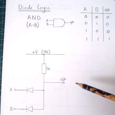
AND gate implemented as diode-resistor logic. (Credit: Anthony Francis-Jones)

The fun part about logic gates is that there are so many ways to make them, with each approach having its own advantages and disadvantages. Although these days transistor-transistor logic (TTL) is the most common, diode-transistor logic (DTL) once was a regular sight, as well as diode-resistor logic (DRL). These logic gates are the topic of a recent video by [Anthony Francis-Jones], covering a range of logic gates implemented using mostly diodes and resistors.

Of note is that there’s another class of logic gates: this uses resistors and transistors (RTL) and preceded DTL. While DRL can be used to implement AND and OR logic gates, some types of logic gates (e.g. NOT) require an active (transistor) element, which is where DTL comes into play.

In addition to the construction of a rather nifty demonstration system and explanation of individual logic gates, [Anthony] also shows off a range of DTL cards used in the Bendix G-15 and various DEC systems. Over time TTL would come to dominate as this didn’t have the diode voltage drop and other issues that prevented significant scaling. Although the rise of VLSI has rendered DRL and DTL firmly obsolete, they still make for a fascinating teaching moment and remind us of the effort over the decades to make the computing device on which you’re reading this possible.

Getting Started with ATtiny Configurable Custom Logic (CCL)

Configurable Custom Logic (CCL) Block Diagram.

In the Microchip tinyAVR 0-series, 1-series, and 2-series we see Configurable Custom Logic (CCL) among the Core Independent Peripherals (CIP) available on the chip. In this YouTube video [Grug Huhler] shows us how to make your own digital logic in hardware using the ATtiny CCL peripheral.

If you have spare pins on your tinyAVR micro you can use them with the CCL for “glue logic” and save on your bill of materials (BOM) cost. The CCL can do simple to moderately complex logic, and it does it without the need for support from the processor core, which is why it’s called a core independent peripheral. A good place to learn about the CCL capabilities in these tinyAVR series is Microchip Technical Brief TB3218: Getting Started with Configurable Custom Logic (CCL) or if you need more information see a datasheet, such as the ATtiny3226 datasheet mentioned in the video.

A tinyAVR micro will have one or two CCL peripherals depending on the series. The heart of the CCL hardware are two Lookup Tables (LUTs). Each LUT can map any three binary inputs into one binary output. This allows each LUT to be programmed with one byte as simple 2-input or 3-input logic, such as NOT, AND, OR, XOR, etc. Each LUT output can optionally be piped through a Filter/Sync function, an Edge Detector, and a Sequencer (always from the lower numbered LUT in the pair). It is also possible to mask-out LUT inputs.

In the source code that accompanies the video [Grug] includes a demonstration of a three input AND gate, an SR Latch using the sequencer, an SR Latch using feedback, and a filter/sync and edge detection circuit. The Arduino library [Grug] uses is Logic.h from megaTinyCore.

We have covered CIP and CCL technology here on Hackaday before, such as back when we showed you how to use an AVR microcontroller to make a switching regulator.

❌