Recently [Colin Leroy-Mira] found himself slipping into a bit of a rabbit hole while investigating why only under Apple II MAME emulation there was a lot of flickering when using the (emulated) Apple II MouseCard. This issue could not be reproduced on real (PAL or NTSC) hardware. The answer all comes down to how the card synchronizes with the system’s vertical blanking (VBL) while drawing to the screen.
The Apple II MouseCard is one of the many peripheral cards produced for the system, originally bundled with a version of MacPaint for the Apple II. While not a super popular card at the time, it nevertheless got used by other software despite this Apple system still being based around a command line interface.
According to the card’s documentation the interrupt call (IRQ) can be set to 50 or 60 Hz to match the local standard. Confusingly, certain knowledgeable people told him that the card could not be synced to the VBL as it had no knowledge of this. As covered in the article and associated MAME issue ticket, it turns out that the card is very much synced with the VBL exactly as described in The Friendly Manual, with the card’s firmware being run by the system’s CPU, which informs the card of synchronization events.
Not too long ago, I was searching for ideas for the next installment of the “Big Chemistry” series when I found an article that discussed the world’s most-produced chemicals. It was an interesting article, right up my alley, and helpfully contained a top-ten list that I could use as a crib sheet for future articles, at least for the ones I hadn’t covered already, like the Haber-Bosch process for ammonia.
Number one on the list surprised me, though: sulfuric acid. The article stated that it was far and away the most produced chemical in the world, with 36 million tons produced every year in the United States alone, out of something like 265 million tons a year globally. It’s used in a vast number of industrial processes, and pretty much everywhere you need something cleaned or dissolved or oxidized, you’ll find sulfuric acid.
Staggering numbers, to be sure, but is it really the most produced chemical on Earth? I’d argue not by a long shot, when there’s a chemical that we make 4.4 billion tons of every year: Portland cement. It might not seem like a chemical in the traditional sense of the word, but once you get a look at what it takes to make the stuff, how finely tuned it can be for specific uses, and how when mixed with sand, gravel, and water it becomes the stuff that holds our world together, you might agree that cement and concrete fit the bill of “Big Chemistry.”
Rock Glue
To kick things off, it might be helpful to define some basic terms. Despite the tendency to use them as synonyms among laypeople, “cement” and “concrete” are entirely different things. Concrete is the finished building material of which cement is only one part, albeit a critical part. Cement is, for lack of a better term, the glue that binds gravel and sand together into a coherent mass, allowing it to be used as a building material.
What did the Romans ever do for us? The concrete dome of the Pantheon is still standing after 2,000 years. Source: Image by Sean O’Neill from Flickr via Monolithic Dome Institute (CC BY-ND 2.0)
It’s not entirely clear who first discovered that calcium oxide, or lime, mixed with certain silicate materials would form a binder strong enough to stick rocks together, but it certainly goes back into antiquity. The Romans get an outsized but well-deserved portion of the credit thanks to their use of pozzolana, a silicate-rich volcanic ash, to make the concrete that held the aqueducts together and built such amazing structures as the dome of the Pantheon. But the use of cement in one form or another can be traced back at least to ancient Egypt, and probably beyond.
Although there are many kinds of cement, we’ll limit our discussion to Portland cement, mainly because it’s what is almost exclusively manufactured today. (The “Portland” name was a bit of branding by its inventor, Joseph Aspdin, who thought the cured product resembled the famous limestone from the Isle of Portland off the coast of Dorset in the English Channel.)
Portland cement manufacturing begins with harvesting its primary raw material, limestone. Limestone is a sedimentary rock rich in carbonates, especially calcium carbonate (CaCO3), which tends to be found in areas once covered by warm, shallow inland seas. Along with the fact that limestone forms between 20% and 25% of all sedimentary rocks on Earth, that makes limestone deposits pretty easy to find and exploit.
Cement production begins with quarrying and crushing vast amounts of limestone. Cement plants are usually built alongside the quarries that produce the limestone or even right within them, to reduce transportation costs. Crushed limestone can be moved around the plant on conveyor belts or using powerful fans to blow the crushed rock through large pipes. Smaller plants might simply move raw materials around using haul trucks and front-end loaders. Along with the other primary ingredient, clay, limestone is stored in large silos located close to the star of the show: the rotary kiln.
Turning and Burning
A rotary kiln is an enormous tube, up to seven meters in diameter and perhaps 80 m long, set on a slight angle from the horizontal by a series of supports along its length. The supports have bearings built into them that allow the whole assembly to turn slowly, hence the name. The kiln is lined with refractory materials to resist the flames of a burner set in the lower end of the tube. Exhaust gases exit the kiln from the upper end through a riser pipe, which directs the hot gas through a series of preheaters that slowly raise the temperature of the entering raw materials, known as rawmix.
The rotary kiln is the centerpiece of Portland cement production. While hard to see in this photo, the body of the kiln tilts slightly down toward the structure on the left, where the burner enters and finished clinker exits. Source: by nordroden, via Adobe Stock (licensed).
Preheating the rawmix drives off any remaining water before it enters the kiln, and begins the decomposition of limestone into lime, or calcium oxide:
The rotation of the kiln along with its slight slope results in a slow migration of rawmix down the length of the kiln and into increasingly hotter regions. Different reactions occur as the temperature increases. At the top of the kiln, the 500 °C heat decomposes the clay into silicate and aluminum oxide. Further down, as the heat reaches the 800 °C range, calcium oxide reacts with silicate to form the calcium silicate mineral known as belite:
Finally, near the bottom of the kiln, belite and calcium oxide react to form another calcium silicate, alite:
It’s worth noting that cement chemists have a specialized nomenclature for alite, belite, and all the other intermediary phases of Portland cement production. It’s a shorthand that looks similar to standard chemical nomenclature, and while we’re sure it makes things easier for them, it’s somewhat infuriating to outsiders. We’ll stick to standard notation here to make things simpler. It’s also important to note that the aluminates that decomposed from the clay are still present in the rawmix. Even though they’re not shown in these reactions, they’re still critical to the proper curing of the cement.
Portland cement clinker. Each ball is just a couple of centimeters in diameter. Source: مرتضا, Public domain
The final section of the kiln is the hottest, at 1,500 °C. The extreme heat causes the material to sinter, a physical change that partially melts the particles and adheres them together into small, gray lumps called clinker. When the clinker pellets drop from the bottom of the kiln, they are still incandescently hot. Blasts of air that rapidly bring the clinker down to around 100 °C. The exhaust from the clinker cooler joins the kiln exhaust and helps preheat the incoming rawmix charge, while the cooled clinker is mixed with a small amount of gypsum and ground in a ball mill. The fine gray powder is either bagged or piped into bulk containers for shipment by road, rail, or bulk cargo ship.
The Cure
Most cement is shipped to concrete plants, which tend to be much more widely distributed than cement plants due to the perishable nature of the product they produce. True, both plants rely on nearby deposits of easily accessible rock, but where cement requires limestone, the gravel and sand that go into concrete can come from a wide variety of rock types.
Concrete plants quarry massive amounts of rock, crush it to specifications, and stockpile the material until needed. Orders for concrete are fulfilled by mixing gravel and sand in the proper proportions in a mixer housed in a batch house, which is elevated above the ground to allow space for mixer trucks to drive underneath. The batch house operators mix aggregate, sand, and any other admixtures the customer might require, such as plasticizers, retarders, accelerants, or reinforcers like chopped fiberglass, before adding the prescribed amount of cement from storage silos. Water may or may not be added to the mix at this point. If the distance from the concrete plant to the job site is far enough, it may make sense to load the dry mix into the mixer truck and add the water later. But once the water goes into the mix, the clock starts ticking, because the cement begins to cure.
Cement curing is a complex process involving the calcium silicates (alite and belite) in the cement, as well as the aluminate phases. Overall, the calcium silicates are hydrated by the water into a gel-like substance of calcium oxide and silicate. For alite, the reaction is:
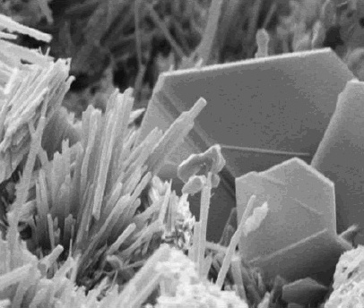
Scanning electron micrograph of cured Portland cement, showing needle-like ettringite and plate-like calcium oxide. Source: US Department of Transportation, Public domain
At the same time, the aluminate phases in the cement are being hydrated and interacting with the gypsum, which prevents early setting by forming a mineral known as ettringite. Without the needle-like ettringite crystals, aluminate ions would adsorb onto alite and block it from hydrating, which would quickly reduce the plasticity of the mix. Ideally, the ettringite crystals interlock with the calcium silicate gel, which binds to the surface of the sand and gravel and locks it into a solid.
Depending on which adjuvants were added to the mix, most concretes begin to lose workability within a few hours of rehydration. Initial curing is generally complete within about 24 hours, but the curing process continues long after the material has solidified. Concrete in this state is referred to as “green,” and continues to gain strength over a period of weeks or even months.
The fact that modern-day x86 processors still pretty much support the same operating systems and software as their ancestors did is quite a feat. Much of this effort had already been accomplished with the release of the 80386 (later 386) CPU in 1985, which was not only the first 32-bit x86 CPU, but was also backwards compatible with 8- and 16-bit software dating back to the 1970s. Making this work transparently was anything but straightforward, as [Ken Shirriff]’s recent analysis of the 80386’s main register file shows.
Labelled Intel 80386 die shot. (Credit: Ken Shirriff)
Using die shots of the 386’s registers and surrounding silicon, it’s possible to piece together how backwards compatibility was implemented. The storage cells of the registers are implemented using static memory (SRAM) as is typical, with much of the register file triple-ported (two read, one write).
Most interestingly is the presence of different circuits (6) to support accessing the register file for 8-, 16- or 32-bit writes and reads. The ‘shuffle’ network as [Ken] calls it is responsible for handling these distinct writes and reads, which also leads to the finding that the bottom 16 bits in the registers are actually interleaved to make this process work smoother.
Fortunately for Intel (and AMD) engineers, this feat wouldn’t have to be repeated again with the arrival of AMD64 and x86_64 many years later, when the 386’s mere 275,000 transistors on a 1 µm process would already be ancient history.
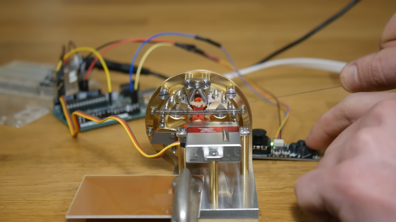
A common ratchet from your garage may work wonders for tightening hard to reach bolts on whatever everyday projects around the house. However, those over at [Chronova Engineering] had a particularly unusual project where a special ratchet mechanism needed to be developed. And developed it was, an absolutely beautiful machining job is done to create a ratcheting actuator for tendon pulling. Yes, this mechanical steampunk-esk ratchet is meant for yanking on the fleshy strings found in all of us.
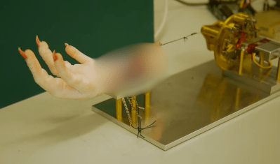
The unique mechanism is necessary because of the requirement for bidirectional actuation for bio-mechanics research. Tendons are meant to be pulled and released to measure the movement of the fingers or toes. This is then compared with the distance pulled from the actuator. Hopefully, this method of actuation measurement may help doctors and surgeons treat people with impairments, though in this particular case the “patient” is a chicken’s foot.
Blurred for viewing ease
Manufacturing the mechanism itself consisted of a multitude of watch lathe operations and pantographed patterns. A mixture of custom and commercial screws are used in combination with a peg gear, cams, and a high performance servo to complete the complex ratchet. With simple control from an Arduino, the system completes its use case very effectively.
In all the actuator is an incredible piece of machining ability with one of the least expected use cases. The original public listed video chose to not show the chicken foot itself due to fear of the YouTube overlords.
If you wish to see the actuator in proper action check out the uncensored and unlisted video here.
Thanks to [DjBiohazard] on our Discord server tips-line!
The future of healthy indoor plants, courtesy of AI. (Credit: [Liam])Like so many of us, [Liam] has a big problem. Whether it’s the curse of Brown Thumbs or something else, those darn houseplants just keep dying despite guides always telling you how incredibly easy it is to keep them from wilting with a modicum of care each day, even without opting for succulents or cactuses. In a fit of despair [Liam] decided to pin his hopes on what we have come to accept as the Savior of Humankind, namely ‘AI’, which can stand for a lot of things, but it’s definitely really smart and can even generate pretty pictures, which is something that the average human can not. Hence it’s time to let an LLM do all the smart plant caring stuff with ‘PlantMom’.
Since LLMs (so far) don’t come with physical appendages by default, some hardware had to be plugged together to measure parameters like light, temperature and soil moisture. Add to this a grow light & a water pump and all that remained was to tell the LMM using an extensive prompt (containing Python code) what it should do (keep the plant alive) and what responses (Python methods) are available. All that was left now was to let the ‘AI’ (Google’s Gemma 3) handle it.
To say that this resulted in a dramatic failure along with what reads like an emotional breakdown (on the side of the LLM) would be an understatement. The LLM insisted on turning the grow light on when it should be off and had the most erratic watering responses imaginable based on absolutely incorrect interpretations of the ADC data (flipping dry vs wet). After this episode the poor chili plant’s soil was absolutely saturated and is still trying to dry out, while the ongoing LLM experiment (with empty water tank) has the grow light blasting more often than a weed farm.
So far it seems like that the humble state machine’s job is still safe from being taken over by ‘AI’, and not even brown thumb folk can kill plants this efficiently.
It’s human nature to look at the technological achievements of the ancients — you know, anything before the 1990s — and marvel at how they were able to achieve precision results in such benighted times. How could anyone create a complicated mechanism without the aid of CNC machining and computer-aided design tools? Clearly, it was aliens.
Or, as [Chris] from Click Spring demonstrates by creating precision nesting thin-wall tubing, it was human beings running the same wetware as what’s running between our ears but with a lot more patience and ingenuity. It’s part of his series of experiments into how the craftsmen of antiquity made complicated devices like the Antikythera mechanism with simple tools. He starts by cleaning up roughly wrought brass rods on his hand-powered lathe, followed by drilling and reaming to create three tubes with incremental precision bores. He then creates matching pistons for each tube, with an almost gas-tight enough fit right off the lathe.
Getting the piston fit to true gas-tight precision came next, by lapping with a jeweler’s rouge made from iron swarf recovered from the bench. Allowed to rust and ground to a paste using a mortar and pestle, the red iron oxide mixed with olive oil made a dandy fine abrasive, perfect for polishing the metal to a high gloss finish. Making the set of tubes concentric required truing up the bores on the lathe, starting with the inner-most tube and adding the next-largest tube once the outer diameter was lapped to spec.
Easy? Not by a long shot! It looks like a tedious job that we suspect was given to the apprentice while the master worked on more interesting chores. But clearly, it was possible to achieve precision challenging today’s most exacting needs with nothing but the simplest tools and plenty of skill.
It’s amazing how quickly medical science made radiography one of its main diagnostic tools. Medicine had barely emerged from its Dark Age of bloodletting and the four humours when X-rays were discovered, and the realization that the internal structure of our bodies could cast shadows of this mysterious “X-Light” opened up diagnostic possibilities that went far beyond the educated guesswork and exploratory surgery doctors had relied on for centuries.
The problem is, X-rays are one of those things that you can’t see, feel, or smell, at least mostly; X-rays cause visible artifacts in some people’s eyes, and the pencil-thin beam of a CT scanner can create a distinct smell of ozone when it passes through the nasal cavity — ask me how I know. But to be diagnostically useful, the varying intensities created by X-rays passing through living tissue need to be translated into an image. We’ve already looked at how X-rays are produced, so now it’s time to take a look at how X-rays are detected and turned into medical miracles.
Taking Pictures
For over a century, photographic film was the dominant way to detect medical X-rays. In fact, years before Wilhelm Conrad Röntgen’s first systematic study of X-rays in 1895, fogged photographic plates during experiments with a Crooke’s tube were among the first indications of their existence. But it wasn’t until Röntgen convinced his wife to hold her hand between one of his tubes and a photographic plate to create the first intentional medical X-ray that the full potential of radiography could be realized.
“Hand mit Ringen” by W. Röntgen, December 1895. Public domain.
The chemical mechanism that makes photographic film sensitive to X-rays is essentially the same as the process that makes light photography possible. X-ray film is made by depositing a thin layer of photographic emulsion on a transparent substrate, originally celluloid but later polyester. The emulsion is a mixture of high-grade gelatin, a natural polymer derived from animal connective tissue, and silver halide crystals. Incident X-ray photons ionize the halogens, creating an excess of electrons within the crystals to reduce the silver halide to atomic silver. This creates a latent image on the film that is developed by chemically converting sensitized silver halide crystals to metallic silver grains and removing all the unsensitized crystals.
Other than in the earliest days of medical radiography, direct X-ray imaging onto photographic emulsions was rare. While photographic emulsions can be exposed by X-rays, it takes a lot of energy to get a good image with proper contrast, especially on soft tissues. This became a problem as more was learned about the dangers of exposure to ionizing radiation, leading to the development of screen-film radiography.
In screen-film radiography, X-rays passing through the patient’s tissues are converted to light by one or more intensifying screens. These screens are made from plastic sheets coated with a phosphorescent material that glows when exposed to X-rays. Calcium tungstate was common back in the day, but rare earth phosphors like gadolinium oxysulfate became more popular over time. Intensifying screens were attached to the front and back covers of light-proof cassettes, with double-emulsion film sandwiched between them; when exposed to X-rays, the screens would glow briefly and expose the film.
By turning one incident X-ray photon into thousands or millions of visible light photons, intensifying screens greatly reduce the dose of radiation needed to create diagnostically useful images. That’s not without its costs, though, as the phosphors tend to spread out each X-ray photon across a physically larger area. This results in a loss of resolution in the image, which in most cases is an acceptable trade-off. When more resolution is needed, single-screen cassettes can be used with one-sided emulsion films, at the cost of increasing the X-ray dose.
Wiggle Those Toes
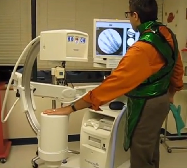
Intensifying screens aren’t the only place where phosphors are used to detect X-rays. Early on in the history of radiography, doctors realized that while static images were useful, continuous images of body structures in action would be a fantastic diagnostic tool. Originally, fluoroscopy was performed directly, with the radiologist viewing images created by X-rays passing through the patient onto a phosphor-covered glass screen. This required an X-ray tube engineered to operate with a higher duty cycle than radiographic tubes and had the dual disadvantages of much higher doses for the patient and the need for the doctor to be directly in the line of fire of the X-rays. Cataracts were enough of an occupational hazard for radiologists that safety glasses using leaded glass lenses were a common accessory.
How not to test your portable fluoroscope. The X-ray tube is located in the upper housing, while the image intensifier and camera are below. The machine is generally referred to as a “C-arm” and is used in the surgery suite and for bedside pacemaker placements. Source: Nightryder84, CC BY-SA 3.0.
One ill-advised spin-off of medical fluoroscopy was the shoe-fitting fluoroscopes that started popping up in shoe stores in the 1920s. Customers would stick their feet inside the machine and peer at a fluorescent screen to see how well their new shoes fit. It was probably not terribly dangerous for the once-a-year shoe shopper, but pity the shoe salesman who had to peer directly into a poorly regulated X-ray beam eight hours a day to show every Little Johnny’s mother how well his new Buster Browns fit.
As technology improved, image intensifiers replaced direct screens in fluoroscopy suites. Image intensifiers were vacuum tubes with a large input window coated with a fluorescent material such as zinc-cadmium sulfide or sodium-cesium iodide. The phosphors convert X-rays passing through the patient to visible light photons, which are immediately converted to photoelectrons by a photocathode made of cesium and antimony. The electrons are focused by coils and accelerated across the image intensifier tube by a high-voltage field on a cylindrical anode. The electrons pass through the anode and strike a phosphor-covered output screen, which is much smaller in diameter than the input screen. Incident X-ray photons are greatly amplified by the image intensifier, making a brighter image with a lower dose of radiation.
Originally, the radiologist viewed the output screen using a microscope, which at least put a little more hardware between his or her eyeball and the X-ray source. Later, mirrors and lenses were added to project the image onto a screen, moving the doctor’s head out of the direct line of fire. Later still, analog TV cameras were added to the optical path so the images could be displayed on high-resolution CRT monitors in the fluoroscopy suite. Eventually, digital cameras and advanced digital signal processing were introduced, greatly streamlining the workflow for the radiologist and technologists alike.
Get To The Point
So far, all the detection methods we’ve discussed fall under the general category of planar detectors, in that they capture an entire 2D shadow of the X-ray beam after having passed through the patient. While that’s certainly useful, there are cases where the dose from a single, well-defined volume of tissue is needed. This is where point detectors come into play.
In medical X-ray equipment, point detectors often rely on some of the same gas-discharge technology that DIYers use to build radiation detectors at home. Geiger tubes and ionization chambers measure the current created when X-rays ionize a low-pressure gas inside an electric field. Geiger tubes generally use a much higher voltage than ionization chambers, and tend to be used more for radiological safety, especially in nuclear medicine applications, where radioisotopes are used to diagnose and treat diseases. Ionization chambers, on the other hand, were often used as a sort of autoexposure control for conventional radiography. Tubes were placed behind the film cassette holders in the exam tables of X-ray suites and wired into the control panels of the X-ray generators. When enough radiation had passed through the patient, the film, and the cassette into the ion chamber to yield a correct exposure, the generator would shut off the X-ray beam.
Another kind of point detector for X-rays and other kinds of radiation is the scintillation counter. These use a crystal, often cesium iodide or sodium iodide doped with thallium, that releases a few visible light photons when it absorbs ionizing radiation. The faint pulse of light is greatly amplified by one or more photomultiplier tubes, creating a pulse of current proportional to the amount of radiation. Nuclear medicine studies use a device called a gamma camera, which has a hexagonal array of PM tubes positioned behind a single large crystal. A patient is injected with a radioisotope such as the gamma-emitting technetium-99, which accumulates mainly in the bones. Gamma rays emitted are collected by the gamma camera, which derives positional information from the differing times of arrival and relative intensity of the light pulse at the PM tubes, slowly building a ghostly skeletal map of the patient by measuring where the 99Tc accumulated.
Going Digital
Despite dominating the industry for so long, the days of traditional film-based radiography were clearly numbered once solid-state image sensors began appearing in the 1980s. While it was reliable and gave excellent results, film development required a lot of infrastructure and expense, and resulted in bulky films that required a lot of space to store. The savings from doing away with all the trappings of film-based radiography, including the darkrooms, automatic film processors, chemicals, silver recycling, and often hundreds of expensive film cassettes, is largely what drove the move to digital radiography.
After briefly flirting with phosphor plate radiography, where a sensitized phosphor-coated plate was exposed to X-rays and then “developed” by a special scanner before being recharged for the next use, radiology departments embraced solid-state sensors and fully digital image capture and storage. Solid-state sensors come in two flavors: indirect and direct. Indirect sensor systems use a large matrix of photodiodes on amorphous silicon to measure the light given off by a scintillation layer directly above it. It’s basically the same thing as a film cassette with intensifying screens, but without the film.
Direct sensors, on the other hand, don’t rely on converting the X-ray into light. Rather, a large flat selenium photoconductor is used; X-rays absorbed by the selenium cause electron-hole pairs to form, which migrate to a matrix of fine electrodes on the underside of the sensor. The current across each pixel is proportional to the amount measured to the amount of radiation received, and can be read pixel-by-pixel to build up a digital image.
Building a Commodore 64 is among the easier projects for retrocomputing fans to tackle. That’s because the C64’s core chipset does most of the heavy lifting; source those and you’re probably 80% of the way there. But what if you can’t find those chips, or if you want more of a challenge than plugging and chugging? Are you out of luck?
Hardly. The video below from [DrMattRegan] is the first in a series on his scratch-built C64 that doesn’t use the core chipset, and it looks pretty promising. This video concentrates on building a replacement for the 6502 microprocessor — actually the 6510, but close enough — using just a couple of EPROMs, some SRAM chips, and a few standard logic chips to glue everything together. He uses the EPROMs as a “rulebook” that contains the code to emulate the 6502 — derived from his earlier Turing 6502 project — and the SRAM chips as a “notebook” for scratch memory and registers to make a Turing-complete random access machine.
[DrMatt] has made good progress so far, with the core 6502 CPU built on a PCB and able to run the Apple II version of Pac-Man as a benchmark. We’re looking forward to the rest of this series, but in the meantime, a look back at his VIC-less VIC-20 project might be informative.
Upgrading RAM on most computers is often quite a straightforward task: look up the supported modules, purchase them, push a couple of levers, remove the old, and install the new. However, this project submitted by [Mads Chr. Olesen] is anything but a simple.
In this project, he sets out to double the RAM on a Olimex A20-OLinuXino-LIME2 single-board computer. The Lime2 came with 1 GB of RAM soldered to the board, but he knew the A20 processor could support more and wondered if simply swapping RAM chips could double the capacity. He documents the process of selecting the candidate RAM chip for the swap and walks us through how U-Boot determines the amount of memory present in the system.
While your desktop likely has RAM on removable sticks, the RAM here is soldered to the board. Swapping the chip required learning a new skill: BGA soldering, a non-trivial technique to master. Initially, the soldering didn’t go as planned, requiring extra steps to resolve issues. After reworking the soldering, he successfully installed both new chips. The moment of truth arrived—he booted up the LIME2, and it worked! He now owns the only LIME2 with 2 GB of RAM.
This project by [Miro] is awesome, not only did he build a replica Enigma machine using modern technologies, but after completing it, he went back and revised several components to make it more usable. We’ve featured Enigma machines here before; they are complex combinations of mechanical and electrical components that form one of the most recognizable encryption methods in history.
His first Enigma machine was designed closely after the original. He used custom PCBs for the plugboard and lightboard, which significantly cleaned up the internal wiring. For the lightboard, he cleverly used a laser printer on semi-transparent paper to create crisp letters, illuminated from behind. For the keyboard, he again designed a custom PCB to connect all the switches. However, he encountered an unexpected setback due to error stack-up. We love that he took the time to document this issue and explain that the project didn’t come together perfectly on the first try and how some adjustments were needed along the way.
The real heart of this build is the thought and effort put into the design of the encryption rotors. These are the components that rotate with each keystroke, changing the signal path as the system is used. In a clever hack, he used a combination of PCBs, pogo pins, and 3D printed parts to replicate the function of the original wheels.
Enigma machine connoisseurs will notice that the wheels rotate differently than in the original design, which leads us to the second half of this project. After using the machine for a while, it became clear that the pogo pins were wearing down the PCB surfaces on the wheels. To solve this, he undertook an extensive redesign that resulted in a much more robust and reliable machine.
In the redesign, instead of using pogo pins to make contact with pads, he explored several alternative methods to detect the wheel position—including IR light with phototransistors, rotary encoders, magnetic encoders, Hall-effect sensors, and more. The final solution reduced the wiring and addressed long-term reliability concerns by eliminating the mechanical wear present in the original design.
The PET opened, showing the motherboard. (Credit: Ken Shirriff)
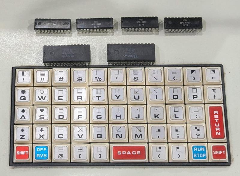
An unavoidable part of old home computer systems and kin like the Commodore PET is that due to the age of their components they will develop issues that go far beyond what was covered in the official repair manual, not to mention require unconventional repairs. A case in point is the 2001 series Commodore PET that [Ken Shirriff] recently repaired.
The initial diagnosis was quite straightforward: it did turn on, but only displayed random symbols on the CRT, so obviously the ICs weren’t entirely happy, but at least the power supply and the basic display routines seemed to be more or less functional. Surely this meant that only a few bad ICs and maybe a few capacitors had to be replaced, and everything would be fully functional again.
Initially two bad MOS MPS6540 ROM chips had to be replaced with 2716 EPROMs using an adapter, but this did not fix the original symptom. After a logic analyzer session three bad RAM ICs were identified, which mostly fixed the display issue, aside from a quaint 2×2 checkerboard pattern and completely bizarre behavior upon running BASIC programs.
Using the logic analyzer capture the 6502 MPU was identified as writing to the wrong addresses. Ironically, this turned out to be due to a wrong byte in one of the replacement 2716 EPROMs as the used programmer wasn’t quite capable of hitting the right programming voltage. Using a better programmer fixed this, but on the next boot another RAM IC turned out to have failed, upping the total of failed silicon to four RAM & two ROM ICs, as pictured above, and teaching the important lesson to test replacement ROMs before you stick them into a system.
This video covers the NEC family of protocols, which are widely used in typical consumer IR remote control devices, and explains how the 38 kHz carrier wave is used to encode a binary signal. [Electronic Wizard] uses his Rigol DS1102 oscilloscope and a breadboard jig to sniff the signal from an example IR controller.
There is also an honorable mention of the HS0038 integrated-circuit which can interpret the light waves and output a digital signal. Of course if you’re a tough guy you don’t need no stinkin’ integrated-circuit IR receiver implementation because you can build your own!
Before the video concludes there is a brief discussion about how to interpret the binary signal using a combination of long and short pulses. If this looks similar to Morse Code to you that’s because it is similar to Morse Code! But not entirely the same, as you will learn if you watch the video!
The “USB C” cable that comes with the Inaya Portable Rechargeable Lamp. (Credit: The Stock Pot, YouTube)
Recently [Dillan Stock] over at The Stock Pot YouTube channel bought a $17 ‘mushroom’ lamp from his local Kmart that listed ‘USB-C rechargeable’ as one of its features, the only problem being that although this is technically true, there’s a major asterisk. This Inaya-branded lamp namely comes with a USB-C cable with a rather prominent label attached to it that tells you that this lamp requires that specific cable. After trying with a regular USB-C cable, [Dillan] indeed confirmed that the lamp does not charge from a standard USB-C cable. So he did what any reasonable person would do: he bought a second unit and set about to hacking it.
[Dillan] also dug more into what’s so unusual about this cable and the connector inside the lamp. As it turns out, while GND & Vcc are connected as normal, the two data lines (D+, D-) are also connected to Vcc. Presumably on the lamp side this is the expected configuration, while using a regular USB-C cable causes issues. Vice versa, this cable’s configuration may actually be harmful to compliant USB-C devices, though [Dillan] did not try this.
With the second unit in hand, he then started hacking it, with the full plans and schematic available on his website.
The changes include a regular USB-C port for charging, an ESP32 board with integrated battery charger for the 18650 Li-ion cell of the lamp, and an N-channel MOSFET to switch the power to the lamp’s LED. With all of the raw power from the ESP32 available, the two lamps got integrated into the Home Assistant network which enables features such as turning the lamps on when the alarm goes off in the morning. All of this took about $7 in parts and a few hours of work.
Although we can commend [Dillan] on this creative hack rather than returning the item, it’s worrying that apparently there’s now a flood of ‘USB C-powered’ devices out there that come with non-compliant cables that are somehow worse than ‘power-only’ USB cables. It brings back fond memories of hunting down proprietary charging cables, which was the issue that USB power was supposed to fix.
We’ve got a love-hate relationship with discount tool outlet Harbor Freight: we hate that we love it so much. Apparently, [James Clough] is of much the same opinion, at least now that he’s looked into the quality of their outlet strips and found it somewhat wanting.
The outlet strips in question are Harbor Freight’s four-foot-long, twelve-outlet strips, three of which are visible from where this is being written. [James] has a bunch of them too, but when he noticed an intermittent ground connection while using an outlet tester, he channeled his inner [Big Clive] and tore one of the $20 strips to bits. The problem appears to be poor quality of the contacts within each outlet, which don’t have enough spring pre-load to maintain connection with the ground pin on the plug when it’s wiggled around. Actually, the contacts for the hot and neutral don’t look all that trustworthy either, and the wiring between the outlets is pretty sketchy too. The video below shows the horrors within.
What’s to be done about this state of affairs? That’s up to you, of course. We performed the same test on all our outlets and the ground connections all seemed solid. So maybe [James] just got a bad batch, but he’s still in the market for better-quality strips. That’s going to cost him, though, since similar strips with better outlets are about four times the price of the Harbor Freight units. We did find a similar strip at Home Depot for about twice the price of the HF units, but we can’t vouch for the quality. As always, caveat emptor.
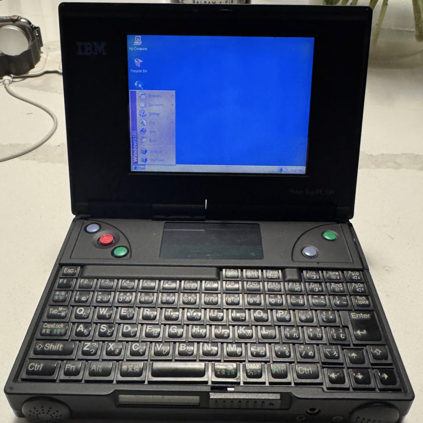
There’s a dedicated group of users out there that aren’t ready to let their beloved IBM PC110 go to that Great Big Data Center in the Sky. Unfortunately, between the limited available technical information and rarity of replacement parts, repairing the diminutive palmtops can be tricky.
Which is why [Ahmad Byagowi] has started a project that aims to not only collect all the available schematics and datasheets that pertain to the machine, but to reverse engineer all of the computer’s original circuit boards. Working from optical and x-ray scans, the project has already recreated the motherboard, power supply, modem, keyboard, and RAM module PCBs in KiCad.
Just last week the project released production-ready Gerbers for all the boards, but considering there have been 45+ commits to the repository since then, we’re going to assume they weren’t quite finalized. Of course, with a project of this magnitude, you’d expect it to take a few revisions to get everything right. (Hell, we’ve managed to screw up board layouts that had fewer than a dozen components on them.)
If you’d like to lend a hand, [Ahmad] says he could use the help. Beyond checking the boards for problems and reporting issues, he’s also on the hunt for any datasheets or other documentation that can be found for the PC110 or its components. It looks like there’s still schematic work that needs to be done as well, so if your idea of zen is figuring out how ~30 year old computers were wired up internally, this might be the perfect summer project for you.
Interestingly, our very own [Arya Voronova] has been working on creating a drop-in replacement motherboard for the Sony Vaio P using KiCad and imported board images. That hobbyists are now able to do this kind of work using free and open source tools is a reminder of just how far things have come in the last few years.
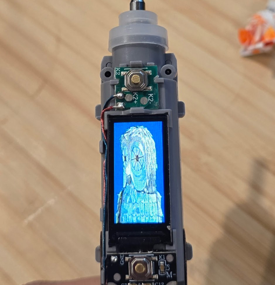
As you might have guessed, this isn’t exactly a hack out of necessity. With a flair for explaining hardware hacking, [wrongbaud] has put this together as a practical “brush-up” (get it?) on the tools and concepts involved in reverse engineering. In this case, the Raspberry Pi is used as a sort of hardware hacking multi-tool, which should make it relatively easy to follow along.
Modified image data on the SPI flash chip.
The first post in the series goes over getting the Pi up and running, which includes setting up OpenOCD. From there, [wrongbaud] actually cracks the toothbrush open and starts identifying interesting components, which pretty quickly leads to the discovery of a debug serial port. The next step is harassing the SPI flash chip on the board to extract its contents. As the toothbrush has a high-res color display (of course it does), it turns out this chip holds the images which indicate the various modes of operation. He’s eventually able to determine how the images are stored, inject new graphics data, and write it back to the chip.
Being able to display the Wrencher logo on our toothbrush would already be a win in our book, but [wrongbaud] isn’t done yet. For the last series in the post, he shows how to extract the actual firmware from the microcontroller using OpenOCD. This includes how to analyze the image, modify it, and eventually flash the new version back to the hardware — using that debug port discovered earlier to confirm the patched code is running as expected.
A spectrometer is one of those tools that many of us would love to have, but just can’t justify the price of. Sure there are some DIY options out there, but few of them have the convenience or capability of what’s on the commercial market. [Chris] from Zoid Technology recently found a portable spectrometer complete with Android application for just $150 USD on AliExpress which looked very promising…at least at first.
The problem is that the manufacturer, Torch Bearer, offers more expensive models of this spectrometer. In an effort to push users into those higher-priced models, arbitrary features such as data export are blocked in the software. [Chris] first thought he could get around this by reverse engineering the serial data coming from the device (interestingly, the spectrometer ships with a USB-to-serial adapter), but while he got some promising early results, he found that the actual spectrometer data was obfuscated — a graph of the results looked like stacks of LEGOs.
That ain’t right — data over the serial link was obfuscated for your protection fleecing
His next step was to decompile the Android application and manually edit out the model number checks. This let him enable the blocked features, although to be fair, he did find that some of them actually did require additional hardware capabilities that this cheaper model apparently doesn’t posses. He was able to fix up a few other wonky issues in the application that are described in the video below, and has released a patch that you can use to bring your own copy of the software up to snuff.
But that’s not all — while fiddling around inside the Android tool’s source code, he found the missing pieces he needed to understand how the serial data was being obfuscated. The explanation to how it works is pretty long-winded, so we’ll save time and just say that the end result was the creation of a Python library that lets you pull data from the spectrometer without relying on any of the manufacturer’s software. This is the kind of thing a lot of people have been waiting for, so we’re eager to see what kind of response the GPLv3 licensed tool gets from the community.
Ever want to get into reverse engineering but don’t know where to start? You’re in luck — [Hash] just dropped a case study in chip glitching that should get you off on the right foot.
The object of this reverse engineering effort in the video below is a Microchip SAM4C32C, removed from one of the many smart electrical meters [Hash] loves to tear into. This microcontroller was supposed to be locked to prevent anyone from sniffing around in the code, but after soldering the chip to a target board and plugging it into a Chip Whisperer, [Hash] was able to find some odd-looking traces on the oscilloscope. Of particular interest was an unusual pattern on the scope while resetting the chip, which led him to an AI-assisted search for potential vulnerabilities. This allowed him to narrow down the target time for a power glitch, and in only a few seconds, the chip was forced to bypass its security bit and drop into its boot loader. With the keys to the kingdom, [Hash] was able to read the firmware and find all sorts of interesting tidbits.
Obviously, chip glitching isn’t always as easy as this, and even when a manufacturer leaves a vector like this in the chip, exploiting it does take some experience and finesse. But, if you’re going to get started glitching, it makes sense to start with the low-hanging fruit, and having [Hash] along for the ride doesn’t hurt either.
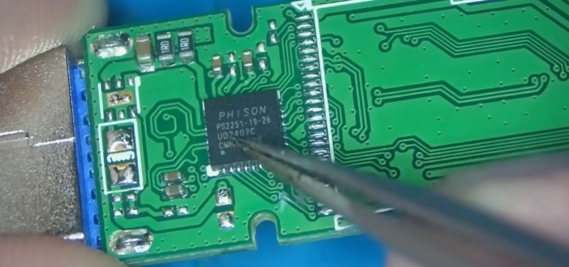
Every year, USB flash drives get cheaper and hold more data. Unfortunately, they don’t always get faster. The reality is, many USB 3.0 flash drives aren’t noticeably faster than their USB 2.0 cousins, as [Chase Fournier] found with the ultra-cheap specimens purchased over at his local Micro Center store.
Although these all have USB 3.0 interfaces, they transfer at less than 30 MB/s, but why exactly? After popping open a few of these drives the answer appears to be that they use the old-style Phison controller (PS2251-09-V) and NAND flash packages that you’d expect to find in a USB 2.0 drive.
Across the 32, 64, and 256 GB variants the same Phison controller is used, but the PCB has provisions for both twin TSOP packages or one BGA package. The latter package turned out to be identical to those found in the iPhone 8. Also interesting was that the two 256 GB drives [Chase] bought had different Phison chips, as in one being BGA and the other QFP. Meanwhile some flash drives use eMMC chips, which are significantly faster, as demonstrated in the video.
It would seem that you really do get what you pay for, with $3 “USB 3.0” flash drives providing the advertised storage, but you really need to budget in the extra time that you’ll be waiting for transfers.


![The future of healthy indoor plants, courtesy of AI. (Credit: [Liam])](https://hackaday.com/wp-content/uploads/2025/04/plantmom_test_setup_with_plant.jpg)


 The real heart of this build is the thought and effort put into the design of the encryption rotors. These are the components that rotate with each keystroke, changing the signal path as the system is used. In a clever hack, he used a combination of PCBs, pogo pins, and 3D printed parts to replicate the function of the original wheels.