Vista de Lectura

Hay nuevos artículos disponibles. Pincha para refrescar la página.

Unsolved Questions in Astronomy? Try Dark Matter!

A false colour image of the region of sky containing the CMZ.

Sometimes in fantasy fiction, you don’t want to explain something that seems inexplicable, so you throw your hands up and say, “A wizard did it.” Sometimes in astronomy, instead of a wizard, the answer is dark matter (DM). If you are interested in astronomy, you’ve probably heard that dark matter solves the problem of the “missing mass” to explain galactic light curves, and the motion of galaxies in clusters.

Now [Pedro De la Torre Luque] and others are proposing that DM can solve another pair of long-standing galactic mysteries: ionization of the central molecular zone (CMZ) in our galaxy, and mysterious 511 keV gamma-rays.

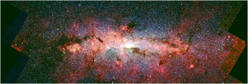
The Central Molecular Zone is a region near the heart of the Milky Way that has a very high density of interstellar gases– around sixty million times the mass of our sun, in a volume 1600 to 1900 light years across. It happens to be more ionized than it ought to be, and ionized in a very even manner across its volume. As astronomers cannot identify (or at least agree on) the mechanism to explain this ionization, the CMZ ionization is mystery number one.

Feynman diagram: Space-time vectors for electron-positron annihilation
Feynman diagram of electron-positron annihilation, showing the characteristic gamma-ray emission.

Mystery number two is a diffuse glow of gamma rays seen in the same part of the sky as the CMZ, which we know as the constellation Sagittarius. The emissions correspond to an energy of 515 keV, which is a very interesting number– it’s what you get when an electron annihilates with the antimatter version of itself. Again, there’s no universally accepted explanation for these emissions.

So [Pedro De la Torre Luque] and team asked themselves: “What if a wizard did it?” And set about trying to solve the mystery using dark matter. As it turns out, computer models including a form of light dark matter (called sub-GeV DM in the paper, for the particle’s rest masses) can explain both phenomena within the bounds of error.

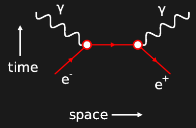
In the model, the DM particles annihilate to form electron-positron pairs. In the dense interstellar gas of the CMZ, those positrons quickly form electrons to produce the 511 keV gamma rays observed. The energy released from this annihilation results in enough energy to produce the observed ionization, and even replicate the very flat ionization profile seen across the CMZ. (Any other proposed ionization source tends to radiate out from its source, producing an uneven profile.) Even better, this sort of light dark matter is consistent with cosmological observations and has not been ruled out by Earth-side dark matter detectors, unlike some heavier particles.

Further observations will help confirm or deny these findings, but it seems dark matter is truly the gift that keeps on giving for astrophysicists. We eagerly await what other unsolved questions in astronomy can be answered by it next, but it leaves us wondering how lazy the universe’s game master is if the answer to all our questions is: “A wizard did it.”

We can’t talk about dark matter without remembering [Vera Rubin].

DIY Record Cutting Lathe is Really Groovy

Back in the day, one of the few reasons to prefer compact cassette tape to vinyl was the fact you could record it at home in very good fidelity. Sure, if you had the scratch, you could go out and get a small batch of records made from that tape, but the machinery to do it was expensive and not always easy to come by, depending where you lived. That goes double today, but we’re in the middle of a vinyl renaissance! [ronald] wanted to make records, but was unable to find a lathe, so decided to take matters into his own hands, and build his own vinyl record cutting lathe.

photograph of [ronald's] setup
[ronald’s] record cutting lathe looks quite professional.
It seems like it should be a simple problem, at least in concept: wiggle an engraving needle to scratch grooves in plastic. Of course for a stereo record, the wiggling needs to be two-axis, and for stereo HiFi you need that wiggling to be very precise over a very large range of frequencies (7 Hz to 50 kHz, to match the pros). Then of course there’s the question of how you’re controlling the wiggling of this engraving needle. (In this case, it’s through a DAC, so technically this is a CNC hack.) As often happens, once you get down to brass tacks (or diamond styluses, as the case may be) the “simple” problem becomes a major project.

The build log discusses some of the challenges faced–for example, [ronald] started with locally made polycarbonate disks that weren’t quite up to the job, so he has resigned himself to purchasing professional vinyl blanks. The power to the cutting head seems to have kept creeping up with each revision: the final version, pictured here, has two 50 W tweeters driving the needle.

That necessitated a better amplifier, which helped improve frequency response. So it goes; the whole project took [ronald] fourteen months, but we’d have to say it looks like it was worth it. It sounds worth it, too; [ronald] provides audio samples; check one out below.  Every garage band in Queensland is going to be beating a path to [ronald’s] door to get their jam sessions cut into “real” records, unless they agree that physical media deserved to die.


Despite the supposedly well-deserved death of physical media, this isn’t the first record cutter we have featured. If you’d rather copy records than cut them, we have that too. There’s also the other kind of vinyl cutter, which might be more your speed.


What’s Sixty Feet Across and Superconducting?

The central solenoid taking shape in the ITER assembly hall.

What’s sixty feet (18.29 meters for the rest of the world) across and superconducting? The International Thermonuclear Experimental Reactor (ITER), and probably not much else.

The last parts of the central solenoid assembly have finally made their way to France from the United States, making both a milestone in the slow development of the world’s largest tokamak, and a reminder that despite the current international turmoil, we really can work together, even if we can’t agree on the units to do it in.

A cutaway diagram of the ITER tokamak showing the central solenoid
The central solenoid is in the “doughnut hole” of the tokamak in this cutaway diagram. Image: US ITER.

The central solenoid is 4.13 m across (that’s 13′ 7″ for burger enthusiasts) sits at the hole of the “doughnut” of the toroidal reactor. It is made up of six modules, each weighing 110 t (the weight of 44 Ford F-150 pickup trucks), stacked to a total height of 59 ft (that’s 18 m, if you prefer). Four of the six modules have be installed on-site, and the other two will be in place by the end of this year.

Each module was produced ITER US, using superconducting material produced by ITER Japan, before being shipped for installation at the main ITER site in France — all to build a reactor based on a design from the Soviet Union. It doesn’t get much more international than this!

This magnet is, well, central to a the functioning of a tokamak. Indeed, the presence of a central solenoid is one of the defining features of this type, compared to other toroidal rectors (like the earlier stellarator or spheromak). The central solenoid provides a strong magnetic field (in ITER, 13.1 T) that is key to confining and stabilizing the plasma in a tokamak, and inducing the 15 MA current that keeps the plasma going.

When it is eventually finished (now scheduled for initial operations in 2035) ITER aims to produce 500 MW of thermal power from 50 MW of input heating power via a deuterium-tritium fusion reaction. You can follow all news about the project here.

While a tokamak isn’t likely something you can hack together in your back yard, there’s always the Farnsworth Fusor, which you can even built to fit on your desk.

Printed Perpetual Calendar Clock Contains Clever Cams

At Hackaday, it is always clock time, and clock time is a great time to check in with [shiura], whose 3D Printed Perpetual Calendar Clock is now at Version 2. A 3D printed calendar clock, well, no big deal, right? Grab a few steppers, slap in an ESP32 to connect to a time server, and you’re good. That’s where most of us would probably go, but most of us aren’t [shiura], who has some real mechanical chops.

The front face of the perpetual calendar clock.
There’s also a 24-hour dial, because why not?

This clock isn’t all mechanical. It probably could be, but at its core it uses a commercial quartz movement — you know, the cheap ones that take a single double-A battery. The only restriction is that the length of the hour axis must be twelve millimeters or more. Aside from that, a few self-tapping screws and an M8 nut, everything else is fully 3D printed.

From that simple quartz movement, [shiura]’s clock tracks not only the day of the week, the month and date — even in Febuary, and even compensating for leap years. Except for the inevitable drift (and battery changes) you should not have to adjust this clock until March 2100, assuming both you and the 3D printed mechanism live that long. Version one actually did all this, too, but somehow we missed it; version two has some improvements to aesthetics and usability. Take a tour of the mechanism in the video after the break.

We’ve featured several of [shiura]’s innovative clocks before, from a hybrid mechanical-analog display, to a splitless flip-clock, and a fully analog hollow face clock. Of course [shiura] is hardly our only clock-making contributor, because it it always clock time at Hackaday.


Non-planar Slicing is for the Birds

Benchy, printed upside down on [Josh's] Core R-Theta printer.

When we say non-planar slicing is for the birds, we mean [Joshua Bird], who demonstrates the versatility of his new non-planar S4-Slicer by printing a Benchy upside down with the “Core R-Theta” printer we have featured here before.

A benchy model, upside down, with the path from the end of the prow to the printbed highlighted.
S4 slicer uses the path from any point (here, Benchy’s prow) as its basis…

This non-planar slicer is built into a Jupyter notebook, which follows a relatively simple algorithm to automatically generate non-planar toolpaths for any model. It does this by first generating a tetrahedral mesh of the model and then calculating the shortest possible path through the model from any given tetrahedron to the print bed. Even with non-planar printing, you need to print from the print-bed up (or out).

Quite a lot of math is done to use these paths to calculate a deformation mesh, and we’ll leave that to [Joshua] to explain in his video below. After applying the deformation, he slices the resulting mesh in Cura, before the G-code goes back to Jupyter to be re-transformed, restoring the shape of the original mesh.

… to generate deformed models for slicing, like this.

So yes, it is G-code bending as others have demonstrated before, but in a reproducible, streamlined, and straightforward workflow. Indeed, [Josh] credits much of the work to earlier work on the S^3-Slicer, which inspired much of the logic and the name behind his S4 slicer. (Not S4 as in “more than S^3” but S4 as a contraction of “Simplified S^3”). Once again, open source allows for incremental innovation.

It is admittedly a computationally intensive process, and [Joshua] uses a simplified model of Benchy for this demo. This seems exactly the sort of thing we’d like to burn compute power on, though.

This sort of non-planar 3D printing is an exciting frontier, one which we have covered before. We’ve seen techniques for non-planar infill, or even to print overhangs on unmodified Cartesian printers,  but this is probably the first time we’ve seen Benchy given the non-planar treatment. You can try S4 slicer for yourself via GitHub, or just watch the non-planar magic in action after the break.


Will it Run Llama 2? Now DOS Can

Two laptops, side by side, running Llama2 in DOS.

Will a 486 run Crysis? No, of course not. Will it run a large language model (LLM)? Given the huge buildout of compute power to do just that, many people would scoff at the very notion. But [Yeo Kheng Meng] is not many people.

He has set up various DOS computers to run a stripped down version of the Llama 2 LLM, originally from Meta. More specifically, [Yeo Kheng Meng] is implementing [Andreq Karpathy]’s Llama2.c library, which we have seen here before, running on Windows 98.

Llama2.c is a wonderful bit of programming that lets one inference a trained Llama2 model in only seven hundred lines of C. It it is seven hundred lines of modern C, however, so porting to DOS 6.22 and the outdated i386 architecture took some doing. [Yeo Kheng Meng] documents that work, and benchmarks a few retrocomputers. As painful as it may be to say — yes, a 486 or a Pentium 1 can now be counted as “retro”.

The models are not large, of course, with TinyStories-trained  260 kB model churning out a blistering 2.08 tokens per second on a generic 486 box. Newer machines can run larger models faster, of course. Ironically a Pentium M Thinkpad T24 (was that really 21 years ago?) is able to run a larger 110 Mb model faster than [Yeo Kheng Meng]’s modern Ryzen 5 desktop. Not because the Pentium M is going blazing fast, mind you, but because a memory allocation error prevented that model from running on the modern CPU. Slow and steady finishes the race, it seems.

This port will run on any 32-bit i386 hardware, which leaves the 16-bit regime as the next challenge. If one of you can get an Llama 2 hosted locally on an 286 or a 68000-based machine, then we may have to stop asking “Does it run DOOM?” and start asking “Will it run an LLM?”

Robot Picks Fruit and Changes Light Bulbs with Measuring Tape

The GRIP-tape robot picking a lemon

How far can you stretch a measuring tape before it buckles? The answer probably depends more on the tape than the user, but it does show how sturdy the coiled spring steel rulers can be. [Gengzhi He et. al.] may have been playing that game in the lab at UC San Diego when they hit upon the idea for a new kind of low-cost robotic gripper.

An image of the GRIP-tape robot described in the article, showing the tape-loop fingers.
Four motors, four strips of measuring tape (doubled up)– one robot hand.

With the lovely backronym “GRIP-tape” — standing for Grasping and Rolling in Plane — you get a sense for what this effector can do. Its two “fingers” are each made of loops of doubled-up measuring tape bound together with what looks suspiciously like duck tape. With four motors total, the fingers can be lengthened or shortened by spooling the tape, allowing  a reaching motion, pivot closer or further apart for grasping, and move-in-place like conveyor belts, rotating the object in their grasp.

The combination means it can reach out, grab a light bulb, and screw it into a socket. Or open and decant a jar of spices. Another video shows the gripper reaching out to pick a lemon, and gently twist it off the tree. It’s quite a performance for a device with such modest components.

At the moment, the gripper is controlled via remote; the researchers plan on adding sensors and AI autonomous control. Read all the details in the preprint, or check below the fold to watch the robot in action.

This is hardly the first time we’ve highlighted a grabby robot. We’ve seen belts, we’ve seen origami — but this is the first time we’ve seen a measuring tape. Have you seen a cool robot? Toss us a tip. We’d love to hear from you.

Tip of the hat to reader [anonymouse] for pointing this one out.

D20-shaped Quasicrystal Makes High-Strength Alloy Printable

An electron microscope image of the aluminum alloy from the study.

When is a crystal not a crystal? When it’s a quasi-crystal, a paradoxical form of metal recently found in some 3D printed metal alloys by [A.D. Iams et al] at the American National Institute for Standards and Technology (NIST).

As you might remember from chemistry class, crystals are made up of blocks of atoms (usually called ‘unit cells’) that fit together in perfect repetition — baring dislocations, cracks, impurities, or anything else that might throw off a theoretically perfect crystal structure. There are only so many ways to tessellate atoms in 3D space; 230 of them, to be precise. A quasicrystal isn’t any of them. Rather than repeat endlessly in 3D space, a quasicrystal never repeats perfectly, like a 3D dimensional Penrose tile. The discovery of quasicrystals dates back to the 1980s, and was awarded a noble prize in 2011.

Penrose tiling of thick and thin rhombi
Penrose tiling– the pattern never repeats perfectly. Quasicrystals do this in 3D. (Image by Inductiveload, Public Domain)

Quasicrystals aren’t exactly common in nature, so how does 3D printing come into this? Well, it turns out that, quite accidentally, a particular Aluminum-Zirconium alloy was forming small zones of quasicrystals (the black spots in the image above) when used in powder bed fusion printing. Other high strength-alloys tended to be very prone to cracking, to the point of unusability, and this Al-Zr alloy, discovered in 2017, was the first of its class.

You might imagine that the non-regular structure of a quasicrystal wouldn’t propagate cracks as easily as a regular crystal structure, and you would be right! The NIST researchers obviously wanted to investigate why the printable alloy had the properties it does. When their crystallographic analysis showed not only five-fold, but also three-fold and two-fold rotational symmetry when examined from different angles, the researchers realized they had a quasicrystal on their hands. The unit cell is in the form of a 20-sided icosahedron, providing the penrose-style tiling that keeps the alloy from cracking.

You might say the original team that developed the alloy rolled a nat-20 on their crafting skill. Now that we understand why it works, this research opens up the doors for other metallic quasi-crystals to be developed on purpose, in aluminum and perhaps other alloys.

We’ve written about 3D metal printers before, and highlighted a DIY-able plastic SLS kit, but the high-power powder-bed systems needed for aluminum aren’t often found in makerspaces. If you’re building one or know someone who is, be sure to let us know.

Budget Schlieren Imaging Setup Uses 3D Printing to Reveal the Unseen

We’re suckers here for projects that let you see the unseeable, and [Ayden Wardell Aerospace] provides that on a budget with their $30 Schlieren Imaging Setup. The unseeable in question is differences in air density– or, more precisely, differences in the refractive index of the fluid the imaging set up makes use of, in this case air. Think of how you can see waves of “heat” on a warm day– that’s lower-density hot air refracting light as it rises. Schlieren photography weaponizes this, allowing to analyze fluid flows– for example, the mach cones in a DIY rocket nozzle, which is what got [Ayden Wardell Aerospace] interested in the technique.

Shock diamonds from a homemade rocket nozzle imaged by this setup.
Examining exhaust makes this a useful tool for [Aerospace].
This is a ‘classic’ mirror-and-lamp Schlieren set up.  You put the system you wish to film near the focal plane of a spherical mirror, and camera and light source out at twice the focal distance. Rays deflected by changes in refractive index miss the camera– usually one places a razor blade precisely to block them, but [Ayden] found that when using a smart phone that was unnecessary, which shocked this author.

While it is possible that [Ayden Wardell Aerospace] has technically constructed a shadowgraph, they claim that carefully positioning the smartphone allows the sharp edge of the case to replace the razor blade. A shadowgraph, which shows the second derivative of density, is a perfectly valid technique for flow visualization, and is superior to Schlieren photography in some circumstances– when looking at shock waves, for example.

Regardless, the great thing about this project is that [Ayden Wardell Aerospace] provides us with STLs for the mirror and smartphone mounting, as well as providing a BOM and a clear instructional video. Rather than arguing in the comments if this is “truly” Schlieren imaging, grab a mirror, extrude some filament, and test it for yourself!

There are many ways to do Schlieren images. We’ve highighted background-oriented techniques, and seen how to do it with a moiré pattern, or even a selfie stick. Still, this is the first time 3D printing has gotten involved and the build video below is quick and worth watching for those sweet, sweet Schlieren images.

Replica of 1880 Wireless Telephone is All Mirrors, No Smoke

Engraving of Alexander Graham Bell's photophone, showing the receiver and its optics

If we asked you to name Alexander Graham Bell’s greatest invention, you would doubtless say “the telephone”; it’s probably the only one of his many, many inventions most people could bring to mind. If you asked Bell himself, though, he would tell you his greatest invention was the photophone, and if the prolific [Nick Bild] doesn’t agree he’s at least intrigued enough to produce a replica of this 1880-vintage wireless telephone. Yes, 1880. As in, only four years after the telephone was patented.

It obviously did not catch on, and is not the sort of thing that comes to mind when we think “wireless telephone”. In contrast to the RF of the 20th century version, as you might guess from the name the photophone used light– sunlight, to be specific. In the original design, the transmitter was totally passive– a tube with a mirror on one end, mounted to vibrate when someone spoke into the open end of the tube. That was it, aside from the necessary optics to focus sunlight onto said mirror. [Nick Bild] skips this and uses a laser as a handily coherent light source, which was obviously not an option in 1880. As [Nick] points out, if it was, Bell certainly would have made use of it.

Bell's selenium-based photophone receiver.
The photophone receiver, 1880 edition. Speaker not pictured.

The receiver is only slightly more complex, in that it does have electronic components– a selenium cell in the original, and in [Nick’s] case a modern photoresistor in series with a 10,000 ohm resistor. There’s also an optical difference, with [Nick] opting for a lens to focus the laser light on his photoresistor instead of the parabolic mirror of the original. In both cases vibration of the mirror at the transmitter disrupts line-of-sight with the receiver, creating an AM signal that is easily converted back into sound with an electromagnetic speaker.

The photophone never caught on, for obvious reasons — traditional copper-wire telephones worked beyond line of sight and on cloudy days–but we’re greatful to [Nick] for dredging up the history and for letting us know about it via the tip line. See his video about this project below.

The name [Nick Bild] might look familiar to regular readers. We’ve highlighted a few of his projects on Hackaday before.

DIY scanning spectrometer is a bright idea

A photograph with labels showing the parts of a DIY scanning spectrometer.

Spectroscopy seems simple: split a beam of light into its constituent wavelengths with a prism or diffraction grating, and measure the intensity of each wavelength. The devil is in the details, though, and what looks simple is often much harder to pull of in practice. You’ll find lots of details in [Gary Boyd]’s write-up of his optical scanning spectrometer project, but no devils.

Schematic diagram of [Gary Boyd]'s spectrometer, showing optical elements and rays of light as well as major physical elements like the motor and linear stage.
Schematic diagram of [Gary Boyd]’s Czerny-Turner type scanning spectrometer.
A scanning spectrometer is opposed to the more usual camera-type spectrometer we see on these pages in that it uses a single-pixel sensor that sweeps across the spectrum, rather than spreading the spectrum across an imaging sensor.

Specifically, [Gary] has implemented a Czerny-Turner type spectrometer, which is a two-mirror design. The first concave mirror culminates the light coming into the spectrometer from its entrance slit, focusing it on a reflective diffraction grating. The second concave mirror focuses the various rays of light split by the diffraction grating onto the detector.

In this case [Gary] uses a cheap VEML 7700 ambient light sensor mounted to a small linear stage from amazon to achieve a very respectable 1 nm resolution in the range from 360 nm to 980 nm. That’s better than the human eye, so nothing to sneeze at — but [Gary] includes some ideas in his blog post to extend that even further. The whole device is controlled via an Arduino Uno that streams data to [Gary]’s PC.

[Gary] documents everything very well, from his optical mounts to the Arduino code used to drive the stepper motor and take measurements from the VEML 7700 sensor. The LED and laser “turrets” used in calibration are great designs as well. He also shares the spectra this device is capable of capturing– everything from the blackbody of a tungsten lamp used in calibration, to a cuvette of tea, to the sun itself as you can see here. If you have a couple minutes, [Gary]’s full writeup is absolutely worth a read.

This isn’t the first spectrometer we’ve highlighted– you might say we’ve shown a whole spectrum of them.

3D Printed Milling Machine is Solid as a Rock

An attractive orange CNC mill sitting ona bench.

There are no shortage of CNC machines in the DIY space these days, but sometimes you just need to do things your own way. That’s what [Chris Borges] decided when he put together this rock-solid, concrete-filled CNC milling machine.

The concrete body of this machine is housed inside a 3D printed shell, which makes for an attractive skin as well as a handy mold. Within the concrete is a steel skeleton, with the ‘rebar’ being made of threaded rods and a length of square tubing to hold the main column. You can see the concrete being poured in around the rebar in the image, or watch it happen in the build video embedded below.

An image of the main column of [Chris]'s CNC mill as the concrete is added. The steel reinforcement is clearly visible.
In goes the concrete, up goes the rigidity.
All three axes slide on linear rails, and are attached to lead screws driven by the omnipresent NEMA 17 steppers. The air-cooled spindle, apparently the weak-point of the design, is attached to a pivoting counterweight, but make no mistake: it is on rails. All-in-all, it looks like a very rigid, and very capable design — [Chris] shows it cutting through aluminum quite nicely.

Given that [Chris] has apparently never used a true mill before, this design came out remarkably well. Between the Bill of Materials and 45 page step-by-step assembly instructions, he’s also done a fantastic job documenting the build for anyone who wants to put one together for themselves.

This isn’t the first concrete-filled project we’ve highlighted from [Chris], you may remember seeing his lathe on these pages. It certainly isn’t the first CNC mill we’ve covered, either.

Vibe Check: False Packages a New LLM Security Risk?

A flowchart demonstrating the exploit described.

Lots of people swear by large-language model (LLM) AIs for writing code. Lots of people swear at them. Still others may be planning to exploit their peculiarities, according to [Joe Spracklen] and other researchers at USTA. At least, the researchers have found a potential exploit in ‘vibe coding’.

Everyone who has used an LLM knows they have a propensity to “hallucinate”– that is, to go off the rails and create plausible-sounding gibberish. When you’re vibe coding, that gibberish is likely to make it into your program. Normally, that just means errors. If you are working in an environment that uses a package manager, however (like npm in Node.js, or PiPy in Python, CRAN in R-studio) that plausible-sounding nonsense code may end up calling for a fake package.

A clever attacker might be able to determine what sort of false packages the LLM is hallucinating, and inject them as a vector for malicious code. It’s more likely than you think– while CodeLlama was the worst offender, the most accurate model tested (ChatGPT4) still generated these false packages at a rate of over 5%. The researchers were able to come up with a number of mitigation strategies in their full paper, but this is a sobering reminder that an AI cannot take responsibility. Ultimately it is up to us, the programmers, to ensure the integrity and security of our code, and of the libraries we include in it.

We just had a rollicking discussion of vibe coding, which some of you seemed quite taken with. Others agreed that ChatGPT is the worst summer intern ever.  Love it or hate it, it’s likely this won’t be the last time we hear of security concerns brought up by this new method of programming.

Special thanks to [Wolfgang Friedrich] for sending this into our tip line.

❌