Like the rest of us, 8-bit hardware is not getting any newer, and failed ROMs are just a fact of life. Of course you can’t call up Commadore corporation for replacement parts anymore, so something is needed. [Peirs Rocks] wasn’t satisfied with the existing options, so he came up with the Software Defined Retro ROM to serve as a drop-in replacement for 2364, 2332, and 2316 ROM chips.
Physically, the Software Defined Retro ROM is a PCB that matches the footprint of the original ROM chip, and holds an STM32F4 family microcontroller with a number of extra pins facing upwards. Some of those pins are for programming, so you can flash the board in-situ without removing it from the system using a Pi Pico. The others pins are jumpers for image selection or chip configuration. Depending which STM32 you use, you can have upto 16 ROM images on the board, at whatever chip select behaviour you require. The ROM’s chip select lines could be configured at the factory to answer to HIGH or LOW, and this board can handle either with a jumper swap.
The documentation on the GitHub is very well done, for which we applaud [Piers]. Instructions and demos are also available in the video embedded below. We could certainly see this hack becoming popular in the retrocomputer community, especially as everything ages and memories continue to, uh, y’know. What were we talking about, again?
Oh, right, ROMs. You might think an mask ROM would last a very long time, but it’s been a very long time since some of these were made. Best to dump them while you still can. If the chip is really far gone electrically, you might try decoding a photograph of the die.
It’s always clock time at Hackaday, and this time we have an interesting hack of a clock by [danjovic]– the CIS4, a Cistercian digital clock.
The Cistertians, in case you weren’t paying close attention to European holy orders during the 13th to 15th centuries were the group of monks you’d most likely have found us in. They were the hackers of the middle ages, establishing monestaries across western Europe that were chock full of hacks– including their own numeral system. Cistercian numerals were much more efficient (in spaces and penstrokes) than the Roman numerals they replaced, and even the “Arabic” numerals that replaced them. A single glyph could record anything from 1 to 9,999. (The Europeans hadn’t yet cottoned on to zero.)
The Cistertian glyphs reduced to a 4×4 display.
Depending how you wanted to count time, a single glyph could be used; it looks like [danjovic] is using the thousands and hundreds portions of the glyph for hours and the tens and ones for minutes. This is all accomplished with a 4×4 neopixel matrix, run by an Attiny85 Digispark with a DS3231 RTC module keeping time. A slight simplification is required to reduce the glyphs to 4×4, but we don’t think the monks would mind. For those of us who don’t wear tonsures, an easy read mode scrolls the time in Arabic numerals. (Which still aren’t super easy,with only 4×4 LEDs to display them. See the demo video embedded below and try and guess the time.)
One nice quality of life feature is an LDR for ambient light detection, to automatically adjust the neopixels’ brightness. The hackiest part, which we thought was really clever, is the enclosure: it’s a cheap LED ceiling light. This provides a diffuser, housing and mounting hardware with decent design for no effort. A 3D-printed mask sits between the diffuser and the LEDs and doubles as a PCB holder. All very elegant.
[danjovic] did include a buzzer in the design, but does say if its been programed to sound off for matins, nones and vespers. In any case, at least it’s easier to read than his binary-coded-octal clock that we featured a few years back. This isn’t our first look at this number system,so evidently people can read them with practice.
Have you made or seen a cool clock? Send us a tip. We always have time for clocks.
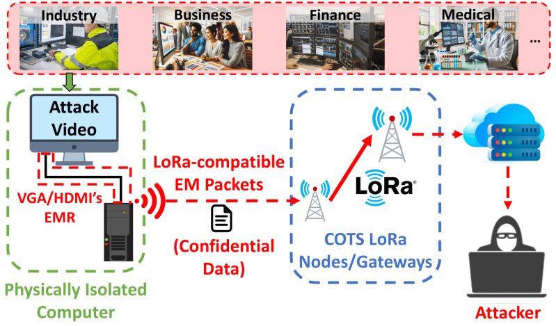
EFI from cables is something every ham loves to hate. What if you modulated, that, though, using an ordinary cable as an antenna? If you used something ubiquitous like a video cable, you might have a very interesting exploit– which is exactly what [Xieyang Sun] and their colleagues have done withTEMPEST-LoRa, a technique to encode LoRa packets into video files.
The concept is pretty simple: a specially-constructed video file contains information to be broadcast via LoRa– the graphics card and the video cable serve as the Tx, and the Rx is any LoRa module. Either VGA or HDMI cables can be used, though the images to create the LoRa signal are obviously going to differ in each case. The only restriction is that the display resolution must be 1080×1920@60Hz, and the video has to play fullscreen. Fullscreen video might make this technique easy to spot if used in an exploit, but on the other hand, the display does not have to be turned on at the time of transmission. If employed by blackhats, one imagines syncing this to power management so the video plays whenever the screen blanks.
This image sends LoRa. Credit: TEMPEST-LoRa
According to the pre-print, a maximum transmission distance of 81.7m was achieved, and at 21.6 kbps. That’s not blazing fast, sure, but transmission out of a totally air-gapped machine even at dialup speeds is impressive. Code is on the GitHub under an MIT license, though [Xieyang Sun] and the team are white hats, so they point out that it’s provided for academic use.There is a demo video, but as it is on bilbili we don’t have an easy way to embed it. The work has been accepted to the ACM Conference on Computer and Communications Security (2025), so if you’re at the event in Taiwan be sure to check it out.
Thanks to [Xieyang Sun] for the tip! We’ll be checking the tips line for word from you, just as soon as we finish wrapping ferrites around all our cables.
Like many of us of a certain vintage, [Dillan Stock] at The Stock Pot is nostalgic for VHS tapes. It’s not so much the fuzzy picture or the tracking issues we miss, but the physical experience the physical medium brought to movie night. To recreate that magic, [Dillan] made a Modern VHS with NFC and ESPHome.
NFC tags are contained in handsomely designed 3D printed cartridges. You can tell [Dillan] put quite a bit of thought into the industrial design of these: there’s something delightfully Atari-like about them, but they have the correct aspect ratio to hold a miniaturized movie poster as a label. They’re designed to print in two pieces (no plastic wasted on supports) and snap together without glue. The printed reader is equally well thought out, with print-in-place springs for that all important analog clunk.
Electronically, the reader is almost as simple as the cartridge: it holds the NFC reader board and an ESP32. This is very similar to NFC-based audio players we’ve featured before, but it differs in the programming. Here, the ESP32 does nothing related directly to playing media: it is simply programmed to forward the NFC tag id to ESPHome. Based on that tag ID, ESPHome can turn on the TV, cue the appropriate media from a Plex server (or elsewhere), or do… well, literally anything. It’s ESPHome; if you wanted to make this and have a cartridge to start your coffee maker, you could.
If this tickles your nostalgia bone, [Dillan] has links to all the code, 3D files and even the label templates on his site. If you’re not sold yet, check out the video below and you might just change your mind. We’ve seen hacks from The Stock Pot before, everything from a rebuilt lamp to an elegant downspout and a universal remote.
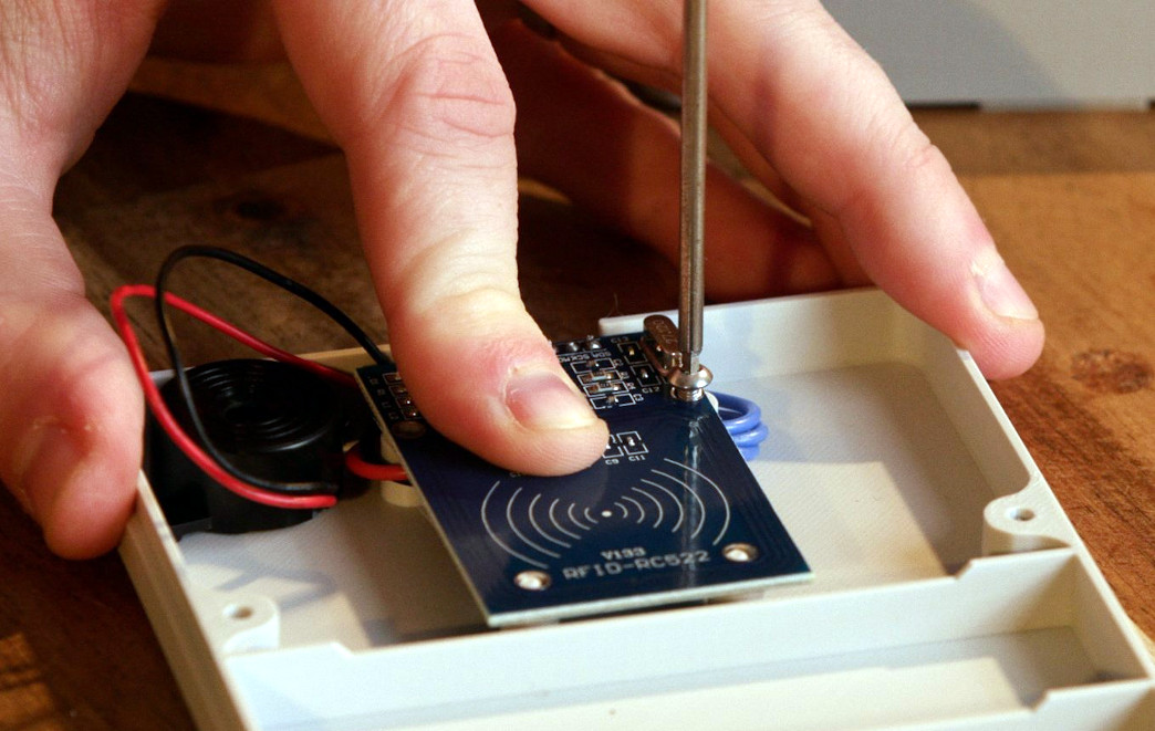
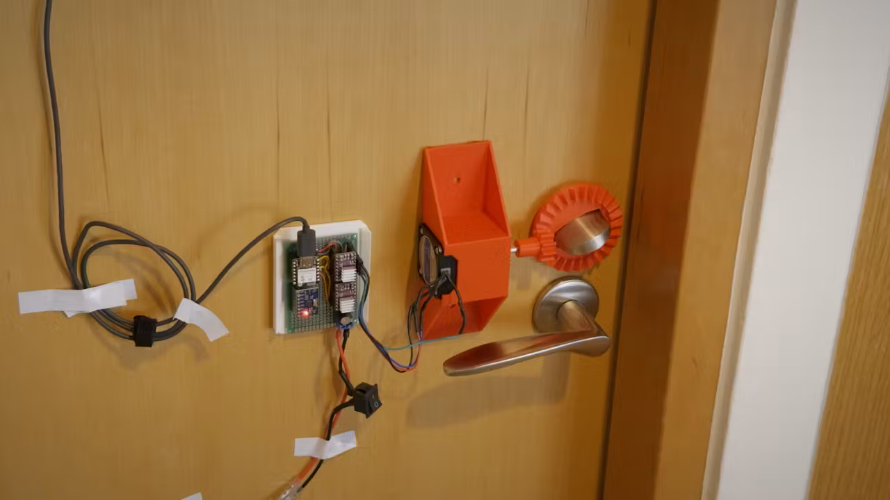
How many times do you have to forget your keys before you start hacking on the problem? For [Binh], the answer was 5 in the last month, and his hack was to make a gesture-based door unlocker. Which leads to the amusing image of [Binh] in a hallway throwing gang signs until he is let in.
The system itself is fairly simple in its execution: the existing deadbolt is actuated by a NEMA 17 stepper turning a 3D printed bevel gear. It runs 50 steps to lock or unlock, apparently, then the motor turns off, so it’s power-efficient and won’t burn down [Binh]’s room.
The software is equally simple; mediapipe is an ML library that can already do finger detection and be accessed via Python. Apparently gesture recognition is fairly unreliable, so [Binh] just has it counting the number of fingers flashed right now. In this case, it’s running on a Rasberry Pi 5 with a webcam for image input. The Pi connects via USB serial to an ESP32 that is connected to the stepper driver. [Binh] had another project ready to be taken apart that had the ESP32/stepper combo ready to go so this was the quickest option. As was mounting everything with double-sided tape, but that also plays into a design constraint: it’s not [Binh]’s door.
[Binh] is staying in a Hacker Hotel, and as you might imagine, there’s been more penetration testing on this than you might get elsewhere. It turns out it’s relatively straightforward to brute force (as you might expect, given it is only counting fingers), so [Binh] is planning on implementing some kind of 2FA. Perhaps a secret knock? Of course he could use his phone, but what’s the fun in that?
Whatever the second factor is, hopefully it’s something that cannot be forgotten in the room. If this project tickles your fancy, it’s open source on GitHub, and you can check it out in action and the build process in the video embedded below.
After offering thanks to [Binh] for the tip, the remaining words of this article will be spent requesting that you, the brilliant and learned hackaday audience, provide us with additional tips.
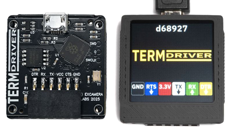
When it comes to text, how small is too small? The experts say a six point font is the minimum for readability, but as [James Bowman] shows us, you can get away with half of that.
The goal is to produce a 40-character display on a 24 mm x 24 mm LCD that has a resolution of 240 x 240 to show a serial terminal (or other data) on the “TermDriver2” USB-to-Serial adapter. With 24 lines, that’s a line per millimeter: very small text. Three points, to be precise, half what the experts say you need. Diving this up into 40 columns gives a character cell of six by nine pixels. Is it enough?
The raw font on the left, the subpixel rendering on the right. For once, it’s better if you don’t click to enlarge.
Not by itself, no. That’s where the hack comes in: sub-pixel rendering. After all, a “white” pixel on an LCD is actually three elements: a red, a green, and a blue subpixel, stacked side-by-each. Drive each of those subpixels independently and 240 pixels now becomes 720. That’s plenty for a 40 column terminal.
The article discusses how, in general terms, they pulled off the subpixel rendering and kept the font as legible as possible. We think it’s a good try, though the colored fringe around the characters can be uncomfortable to look at for some people — and then we can’t forget the physical size of the characters being 1 mm tall.
If this trick were being used on a larger display with a 240-wide resolution, we’d say “yes, very legible, good job!”– but at this size? We hope we can find our reading glasses. Still, it’s a neat trick to have in your back pocket for driving low-resolution LCDs.
The last interesting thing to happen in Donald, BC was when it burned down in the 1910s.
Well, they’ve thankfully moved out of the tent in their parents’ back yard where the prototype was built. They’ve bought themselves a company town: Donald, British Columbia, complete with a totally-not-controversial slogan “Make Donald Great Again”.
More interesting is that their commercial-off-the-shelf (COTS), right-to-repair centered approach isn’t just for semi-trucks: they’re now a certified OEM manufacturer of a rolling heavy truck chassis you can put your truck cab or RV body on, and they have partnered with three coach-builders for RVs and a goodly number of manufacturing partners for truck conversion kits. The kits were always in the plan, but selling the rolling chassis is new.
One amazingly honest take-away from the video is the lack of numbers for the pickups: top speed, shaft horsepower, torque? They know what all that should be, but unlike the typical vaporware startup, Edison won’t tell you the engineering numbers on the pickup truck kits until it has hit the race track and proved itself in the real world. These guys are gear-heads first and engineers second, so for once in a long time the adage “engineers hate mechanics” might not apply to a new vehicle.
The dirt track is the first thing under construction in Donald, so hopefully the next update we hear from Edison Motors will include those hard numbers, including pesky little things like MSRP and delivery dates. Stay tuned.
In our last post about an electric truck, a lot of you in the comments wanted something bigger, heavier duty, not pure battery, and made outside the USA. Well, here it is.
When you hear “PS2” and “Windows 95,” you probably think someone forgot a slash and are talking about peripherals, but no — this hack is very much about the Sony PlayStation 2, the best-selling game console of all time. [MeraByte] walks us through the possibly ridiculous task of installing Windows 95 on the last hardware anyone at Microsoft would ever endorse in a video you can watch below.
Obviously, the MIPS-based Emotion Engine at the heart of the PS2 is not going to be able to handle x86 instructions Win95 is expecting, but that’s all solved by the magic of emulation. [MeraByte] is running a version of Bochs, an x86 emulator that has been built for PS/2 after trying and failing to install Windows (both 3.1 and 95) to an experimental DOSBox build.
As expected, it is not a smooth journey for [MeraByte], but the flailing about and troubleshooting make for entertaining viewing. Once loaded, it works surprisingly well, in that anything works at all. Unfortunately, neither the mouse nor Ultimate Doom 95 worked. We suppose that ultimately means that this hack fails since even Doom can run Doom. The mouse thing is also important, probably.
If you have a PlayStation 2, maybe skip Windows 95 and try running GoLang. If you do have DOOM running on the PlayStation 2, send us a tip. There was never an official release for PS2, but after 26 years, someone must have done it by now.
You know what the worst thing about the Steam Deck is? Being able to play your games on the go. Wouldn’t it be better if it was a screenless brick that lived under your TV? Well, maybe not, but at least one person thought so, because [Interfacing Linux] has created the GeekDeck, a Steam OS console of sorts in this video embedded below.
The hack is as simple as can be: he took a GEEKOM A5, a minicomputer with very similar specs to the Steam Deck, and managed to load SteamOS onto it. We were expecting that to be a trial that took most of the video’s runtime, but no! Everything just… sorta worked. It booted to a live environment and installed like any other Linux. Which was unexpected, but Steam has released SteamOS for PC.
In case you weren’t aware, SteamOS is an immutable distribution based on Arch Linux. Arch of course has all the drivers to run on… well, any modern PC, but it’s the immutable part that we were expecting to cause problems. Immutable distributions are locked down in a similar manner to Mac OS (everything but /home/ is typically read-only, even to the superuser) and SteamOS doesn’t ship with package manager that can get around this, like rpm-ostree in Fedora’s Silverblue ecosystem. Actually, if you don’t have a hardware package that matches the SteamDeck to the same degree this GEEKOM does, Bazzite might be a good bet– it’s based on Siverblue and was made to be SteamOS for PC, before Steam let you download their OS to try on your PC.
Anyway, you can do it. Should you? Well, based on the performance shown in the video, not if you want to run triple-A games locally. This little box is no more powerful than the SteamDeck, after all. It’s not a full gaming rig. Still, it was neat to see SteamOS off of the ‘deck and in the wild.
Usually we see hacks that use the guts of the SteamDeck guts with other operating systems, not the other way around. Like the Bento Box AR machine we liked so much it was actually featured twice. The SteamDeck makes for a respectable SBC, if you can find a broken one. If not, apparently a Chinese MiniPC will work just as well.
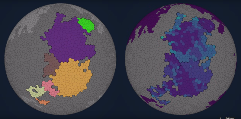
Procedural generation is a big part of game design these days. Usually you generate your map, and [Fractal Philosophy] has decided to go one step further: using a procedurally-generated world from an older video, he is procedurally generating history by simulating the rise and fall of empires on that map in a video embedded below.
Now, lacking a proper theory of Psychohistory, [Fractal Philosophy] has chosen to go with what he admits is the simplest model he could find, one centered on the concept of “solidarity” and based on the work of [Peter Turchin], a Russian-American thinker. “Solidarity” in the population holds the Empire together; external pressures increase it, and internal pressures decrease it. This leads to an obvious cellular automation type system (like Conway’s Game of Life), where cells are evaluated based on their nearest neighbors: the number of nearest neighbors in the empire goes into a function that gives the probability of increasing or decreasing the solidarity score each “turn”. (Probability, in order to preserve some randomness.) The “strength” of the Empire is given by the sum of the solidarity scores in every cell.
Each turn, Empires clash, with the the local solidarity, sum strength, and distance from Imperial center going into determining who gains or loses territory. It is a simple model; you can judge from the video how well it captures the ebb and flow of history, but we think it did surprisingly well all things considered. The extra 40-minute video of the model running is oddly hypnotic, too.
In v2 of the model, one of these fluffy creatures will betray you.
After a dive into more academic support for the main idea, and a segue into game theory and economics, a slight complication is introduced later in the video, dividing each cell into two populations: “cooperators” or “selfish” individuals.
This allows for modeling of internal conflicts between the two groups. This hitch gives a very similar looking map at the end of its run, although has an odd quirk that it automatically starts with a space-filling empire across the whole map that quickly disintegrates.
Unfortunately, the model not open-source, but the ideas are discussed in enough detail that one could probably produce a very similar algorithm in an afternoon. For those really interested, [Fractal Philosophy] does offer a one-time purchase through his Patreon. It also includes the map-generating model from his last video.
Kumiko is a form of Japanese woodworking that uses small cuts of wood (probably offcuts) to produce artful designs. It’s the kind of thing that takes zen-like patience to assemble, and years to master– and who has time for that? [Paper View] likes the style of kumiko, but when all you have is a 3D printer, everything is extruded plastic.
His video, embedded below, focuses mostly on the large tiled piece and the clever design required to avoid more than the unavoidable unsightly seams without excessive post processing. (Who has time for that?) The key is a series of top pieces to hide the edges where the seams come together. The link above, however, gives something more interesting, even if it is on Makerworld.
[Paper View] has created a kumiko-style (out of respect for the craftspeople who make the real thing, we won’t call this “kumiko”) panel generator, that allows one to create custom-sized frames to print either in one piece, or to assemble as in the video. We haven’t looked at MakerWorld’s Parametric Model Maker before, but this tool seems to make full use of its capabilities (to the point of occasionally timing out). It looks like this is a wrapper for OpenScad (just like Thingiverse used to do with Customizer) so there might be a chance if enough of us comment on the video [Paper View] can be convinced to release the scad files on a more open platform.
Multimaterial printing was not invented by BambuLabs, but love them or hate them the AMS has become the gold standard for a modern multi-material unit. [Daniel]’s latest Mod Bot video on the Box Turtle MMU (embedded below) highlights an open source project that aims to bring the power and ease of AMS to Voron printers, and everyone else using Klipper willing to put in the work.
This isn’t a torture test, but it’s very clean and very cute.
The system itself is a mostly 3D printed unit that sits atop [Daniel]’s Voron printer looking just like an AMS atop a BambuLab. It has space for four spools, with motorized rollers and feeders in the front that have handy-dandy indicator LEDs to tell you which filament is loaded or printing. Each spool gets its own extruder, whose tension can be adjusted manually via thumbscrew. A buffer unit sits between the spool box and your toolhead.
Aside from the box, you need to spec a toolhead that meets requirements. It needs a PTFE connector with a (reverse) boden tube to guide the filament, and it also needs to have a toolhead filament runout sensor. The sensor is to provide feedback to Klipper that the filament is loaded or unloaded. Finally you will probably want to add a filament cutter, because that happens at the toolhead with this unit. Sure, you could try the whole tip-forming thing, but anyone who had a Prusa MMU back in the day can tell you that is easier said than done. The cutter apparently makes this system much more reliable.
In operation, it looks just like a BambuLabs printer with an AMS installed. The big difference, again, is that this project by [Armored Turtle] is fully open source, with everything on GitHub under a GPL-3.0 license. Several vendors are already producing kits; [Daniel] is using the LDO version in his video.
It looks like the project is well documented–and [Mod Bot] agrees, and he reports that the build process is not terribly difficult (well, if you’re the kind of person who builds a Voron, anyway), and adding the AFC Klipper Addon (also by [Armored Turtle]) was easy as pie. After that, well. It needs calibration. Calibration and lots of tuning, which is an ongoing process for [Daniel]. If you want to see that, watch the video below, but we’ll spoil it for you and let you know it really pays off. (Except for lane 4, where he probably needs to clean up the print.)We’ve featured open-source MMUs before, like the Enraged Rabbit Carrot Feeder, but it’s great to see more in this scene, especially something that looks like it can take on the AMS. It’s not the only way to get multimaterial– there’s always tool-changers, or you could just put in a second motion system and gantry.
Coming in hot from Cornell University, students [Amanda Huang], [Caroline Hohner], and [Rhea Goswami] bring a project that is guaranteed to tickle the funny bone of anyone in the under-40 set, and sadists of all ages: The Tamagochi Torture Chamber.
He’s dead, Jim.
In case you somehow missed it, Bandai’s Tamagochi is a genre-defining digital pet that was the fad toy at the turn of the millennium, and has had periodic revivals since. Like the original digital pet, there are three pushbuttons to allow you to feed, play with, and clean your digital pet. These affect the basic stats of happiness, health, food and weight in ways that will be familiar to anyone who played with the original Tamagochi. Just as with the original, mistreatment or neglect causes the Tamagochi to “die” and display a tombstone on the TFT display.
Where the “Torture Chamber” part comes in is the presence of an accelerometer and soft physics simulation– the soft physics gets an entire core of the Pi Pico at the heart of this build dedicated to it, while the other core handles all inputs, display and game logic. What this enables is the ability to bounce the digital pet off the walls of its digital home with an adorable squish (and drop in health stat) by tilting the unit. You can check that out in the demo video blow.
Is it overkill for a kids toy to have a full soft body simulation, rather than just a squish-bounce animation? Probably, but for an ECE project, it lets the students show off their chops… and possibly work out some frustrations.
If you’ve got an innovative way to torture video game characters, or a project less likely to get you on Skynet’s hitlist, don’t forget to send in a tip!
We like scale models here, but how small can you shrink the very large? If you’re [Frans], it’s pretty small indeed: his Micro Tellurium fits the orbit of the Earth on top of an ordinary pencil. While you’ll often see models of Earth, Moon and Sun’s orbital relationship called “Orrery”, that’s word should technically be reserved for models of the solar system, inclusive of at least the classical planets, like [Frans]’s Gentleman’s Orrery that recently graced these pages. When it’s just the Earth, Moon and Sun, it’s a Tellurium.
The whole thing is made out of brass, save for the ball-bearings for the Earth and Moon. Construction was done by a combination of manual milling and CNC machining, as you can see in the video below. It is a very elegant device, and almost functional: the Earth-Moon system rotates, simulating the orbit of the moon when you turn the ring to make the Earth orbit the sun. This is accomplished by carefully-constructed rods and a rubber O-ring.
Unfortunately, it seems [Franz] had to switch to a thicker axle than originally planned, so the tiny moon does not orbit Earth at the correct speed compared to the solar orbit: it’s about half what it ought to be. That’s unfortunate, but perhaps that’s the cost one pays when chasing smallness. It might be possible to fix in a future iteration, but right now [Franz] is happy with how the project turned out, and we can’t blame him; it’s a beautiful piece of machining.
It should be noted that there is likely no tellurium in this tellurium — the metal and the model share the same root, but are otherwise unrelated. We have featured hacks with that element, though.
Thanks to [Franz] for submitting this hack. Don’t forget: the tips line is always open, and we’re more than happy to hear you toot your own horn, or sing the praises of someone else’s work.
Have you ever finished up a bit of code and thought that typing “git push” in a terminal is just not a satisfying finish? So did [penumbriel], so he built a big red button he could smash instead.
This is a very simple hack: an Arduino sits inside a 3D-printed case that holds a big, red button. The case itself is very sturdily made to withstand a good satisfying smack: it has thick walls, brass insets, and rubber feet to protect the de The code for the Arduino is very, very simple: it spoofs a USB HID using the standard keyboard library, and automatically types out “git push” whenever the button is pressed. Or smashed, because you know you’re going to want to slam that thing. So far, so good– very innovative for 2006, right?
The detail that made this project stand out in 2025 was the technique [penumbriel] used for lettering– we’re always looking
With a simple soap-and-water mask, the cured silicone peels right off, leaving a clean label.
for new ways to make a good front panel. In this case, the letters were printed as a valley, and filled with silicone adhesive. To protect the top surface of the print, soapy water was used as a mask. The silicone would not adhear to the wet plastic, so all [penumbriel] had to do was peel it off after it had cured, leaving solid white inside. It’s a neat trick, and a great way to use up an old tube of silicone before it goes hard. You could also use it for injection molding, but this is a great use for the dregs.
This might go well next to the programmer’s macro pad we featured a while back, but it really needs to stay as a big red button for maximum satisfaction.
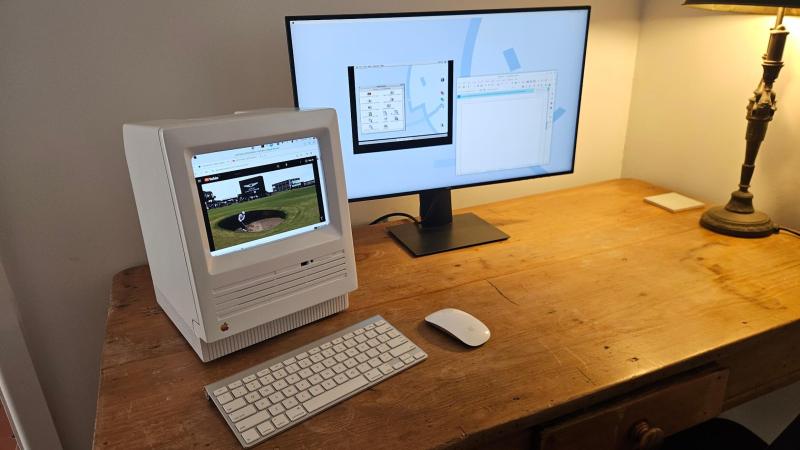
If he’s anything like us [Duncan Hall] was probably equal parts excited and disgusted when he found a 1987 Macintosh SE case at a garage sale. Excited, because not every day do vintage computers show up at these things. Disgusted, because it had been gutted and coated in house paint; the previous owner apparently wanted to make an aquarium. [Duncan] wanted to make a computer, and after 15 years, he finally did, calling it the PhoeNIX SE.
Note the small hole in the top floppy bay for the laptop webcam.
The NIX part of the name might make you suspect he’s running Linux on it, which yes, he absolutely is. The guts of this restomod were donated from a Dell XPS laptop, whose Core i7 CPU and motherboard power the project. A 9.7″ LCD serves in place of the original monochrome CRT, held in place by 3D printed hardware. While a purist might complain, it’s not like anyone makes replacement CRTs anymore, and once that’s gone? You might as well go full modern. (The analog board, on the other hand, is available. So is the logic board, if you were wondering. Lacking a CRT, some might have chosen e-ink instead, but the LCD looks good here.)
All ports are on the rear, as Steve would have wanted. That original sticker survived under latex paint is a spot of luck.
Having gone full modern, well, there’s no need for the M5011’s dual floppies, so one of them holds a webcam and monitor for a modern experience. A zoom call from that case would be a bit surreal, but we really appreciate the use of the empty floppy bay to keep the clean lines of the Macintosh SE unaltered. The other floppy bay (this is a dual-floppy unit) appears empty; we might have put an SD-card reader or something in there, but we absolutely agree with [Duncan]’s choice to 3D Print a new back panel and keep all I/O on the rear of the case, as God and Steve Jobs intended.
However you feel about restomodding retrocomputers (and we’re aware it’s a controversial practice), I think we can all agree this is a much better fate for the old Mac than becoming an aquarium. Thanks to [Loddington] for the tip.
If you’re on the side of the aisle that prefers to see restorations than restomods, the tips line is waiting for some quality restorations.
We’ve seen a lot of projects based on the Pi Pico, but a nuclear reactor simulation is a new one. This project was created by [Andrew Shim], [Tyler Wisniewski] and another group member for Cornell’s ECE 4760 class on embedded design (which should silence naysayers who think the Pi Pico can’t be a “serious” microcontroller), and simulates the infamous soviet RMBK reactor of Chernobyl fame.
The simulation uses a 4-bit color VGA model. The fission model includes uranium fuel, water, graphite moderator, control rods and neutrons. To simplify the math, all decayed materials are treated identically as non-fissile, so no xenon poisoning is going to show up, for example. You can, however, take manual control to both scram the reactor and set it up to melt down with the hardware controller.
The RP2040’s dual-core nature comes in handy here: one core runs the main simulation loop, and the main graphic on the top of the VGA output; the other core generates the plots on the bottom half of the screen, and the Geiger-counter sound effect, and polls the buttons and encoders for user input. This is an interesting spread compared to the more usual GPU/CPU split we see on projects that use the RP2040 with VGA output.
An interesting wrinkle that has been declared a feature, not a bug, by the students behind this project, is that the framebuffer cannot keep up with all the neutrons in a meltdown simulation. Apparently the flickering and stuttering of frame-rate issues is “befitting of the meltdown scenario”. The idea that ones microcontroller melts down along with the simulated reactor is rather fitting, we agree. Check it out in a full walkthrough in the video below, or enjoy the student’s full writeup at the link above.
This project comes to us via Cornell University’s ECE 4760 course, which we’ve mentioned before. Thanks to [Hunter Adams] for the tipoff. You may see more student projects in the coming weeks.
Where’s the best place for a datacenter? It’s an increasing problem as the AI buildup continues seemingly without pause. It’s not just a problem of NIMBYism; earthly power grids are having trouble coping, to say nothing of the demand for cooling water. Regulators and environmental groups alike are raising alarms about the impact that powering and cooling these massive AI datacenters will have on our planet.
While Sam Altman fantasizes about fusion power, one obvious response to those who say “think about the planet!” is to ask, “Well, what if we don’t put them on the planet?” Just as Gerald O’Niell asked over 50 years ago when our technology was merely industrial, the question remains:
“Is the surface of a planet really the right place for expanding technological civilization?”
O’Neill’s answer was a resounding “No.” The answer has not changed, even though our technology has. Generative AI is the latest and greatest technology on offer, but it turns out it may be the first one to make the productive jump to Earth Orbit. Indeed, it already has, but more on that later, because you’re probably scoffing at such a pie-in-the-sky idea.
There are three things needed for a datacenter: power, cooling, and connectivity. The people at companies like Starcloud, Inc, formally Lumen Orbit, make a good, solid case that all of these can be more easily met in orbit– one that includes hard numbers.
Sure, there’s also more radiation on orbit than here on earth, but our electronics turn out to be a lot more resilient than was once thought, as all the cell-phone cubesats have proven. Starcloud budgets only 1 kg of sheilding per kW of compute power in their whitepaper, as an example. If we can provide power, cooling, and connectivity, the radiation environment won’t be a showstopper.
Power
There’s a great big honkin’ fusion reactor already available for anyone to use to power their GPUs: the sun. Of course on Earth we have tricky things like weather, and the planet has an annoying habit of occluding the sun for half the day but there are no clouds in LEO. Depending on your choice of orbit, you do have that annoying 45 minutes of darkness– but a battery to run things for 45 minutes is not a big UPS, by professional standards. Besides, the sun-synchronous orbits are right there, just waiting for us to soak up that delicious, non-stop solar power.
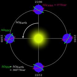
Sun Synchronous Orbit, because nights are for squats. Image by Brandir via Wikimedia.
Sun-synchronous orbits (SSOs) are polar orbits that precess around the Earth once every sidereal year, so that they always maintain the same angle to the sun. For example, you might have an SSO that crosses the equator 12 times a day, each time at local 15:00, or 10:43, any other time set by the orbital parameters. With SSOs, you don’t have to worry about ever losing solar power to some silly, primitive, planet-bound concept like nighttime.
Without the atmosphere in the way, solar panels are also considerably more effective per unit area, something the Space Solar Power people have been pointing out since O’Neill’s day. The problem with Space Solar Power has always been the efficiencies and regulatory hurdles of beaming the power back to Earth– but if you use the power to train an AI model, and send the data down, that’s no longer an issue. Given that the 120 kW array on ISS has been trouble-free for decades now, we can consider it a solved problem. Sure, solar panels degrade, but the rate is in fractions of a percent per year, and it happens on Earth too. By the time solar panel replacement is likely to be the rest of the hardware is likely to be totally obsolete.
Cooling
This is where skepticism creeps in. After all, cooling is the greatest challenge with high performance computing hardware here on earth, and heat rejection is the great constraint of space operations. The “icy blackness of space” you see in popular culture is as realistic as warp drive; space is a thermos, and shedding heat is no trivial issue. It is also, from an engineering perspective, not a complex issue. We’ve been cooling spacecraft and satellites using radiators to shed heat via infrared emission for decades now. It’s pretty easy to calculate that if you have X watts of heat to reject at Y degrees, you will need a radiator of area Z. The Stephan-Boltzmann Law isn’t exactly rocket science.
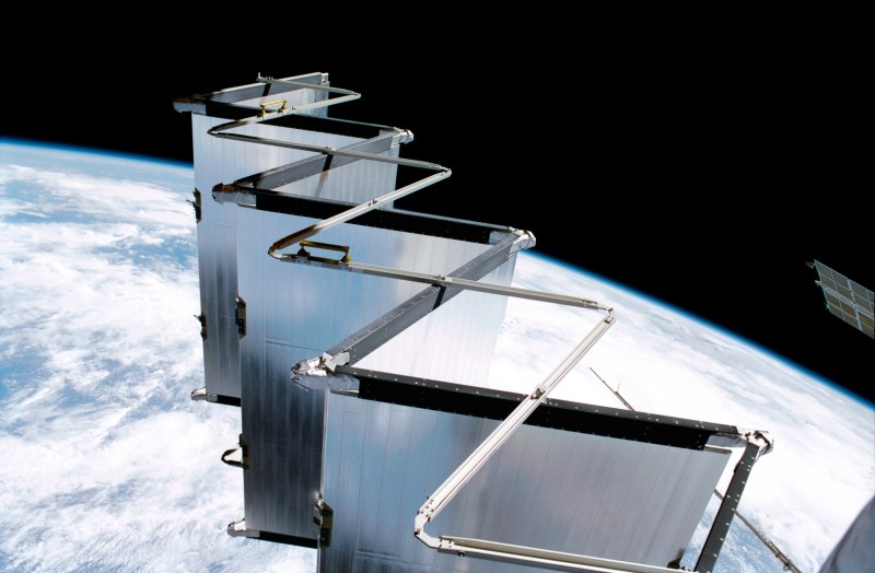
Photons go out, liquid cools down. It might be rocket science, but it’s a fairly mature technology. (Image: EEATCS radiator deployment during ISS Flight 5A, NASA)
Even better, unlike on Earth where you have changeable things like seasons and heat waves, in a SSO you need only account for throttling– and if your data center is profitable, you won’t be doing much of that. So while you need a cooling system, it won’t be difficult to design. Liquid or two-phase cooling on server hardware? Not new. Plumbing cooling a loop to a radiator in the vacuum of space? That’s been part of satellite busses for years.
Aside from providing you with a stable thermal environment, the other advantage of an SSO is that if one chooses the dawn/dusk orbit along the terminator, while the solar panels always face the sun, the radiators can always face black space, letting them work to their optimal potential. This would also simplify the satellite bus, as no motion system would be required to keep the solar panels and radiators aligned into/out of the sun. Conceivably the whole thing could be stabilized by gravity gradient, minimizing the need to use reaction wheels.
Connectivity
One word: Starlink. That’s not to say that future data centers will necessarily be hooking into the Starlink network, but high-bandwidth operations on orbit are already proven, as long as you consider 100 gigabytes per second sufficient bandwidth. An advantage not often thought of for this sort of space-based communications is that the speed of light in a vacuum is about 31% faster than glass fibers, while the circumference of a low Earth orbit is much less than 31% greater than the circumference of the planet. That reduces ping times between elements of free-flying clusters or clusters and whatever communications satellite is overhead of the user. It is conceivable, but by no means a sure thing, that a user in the EU might have faster access to orbital data than they would to a data center in the US.
The Race
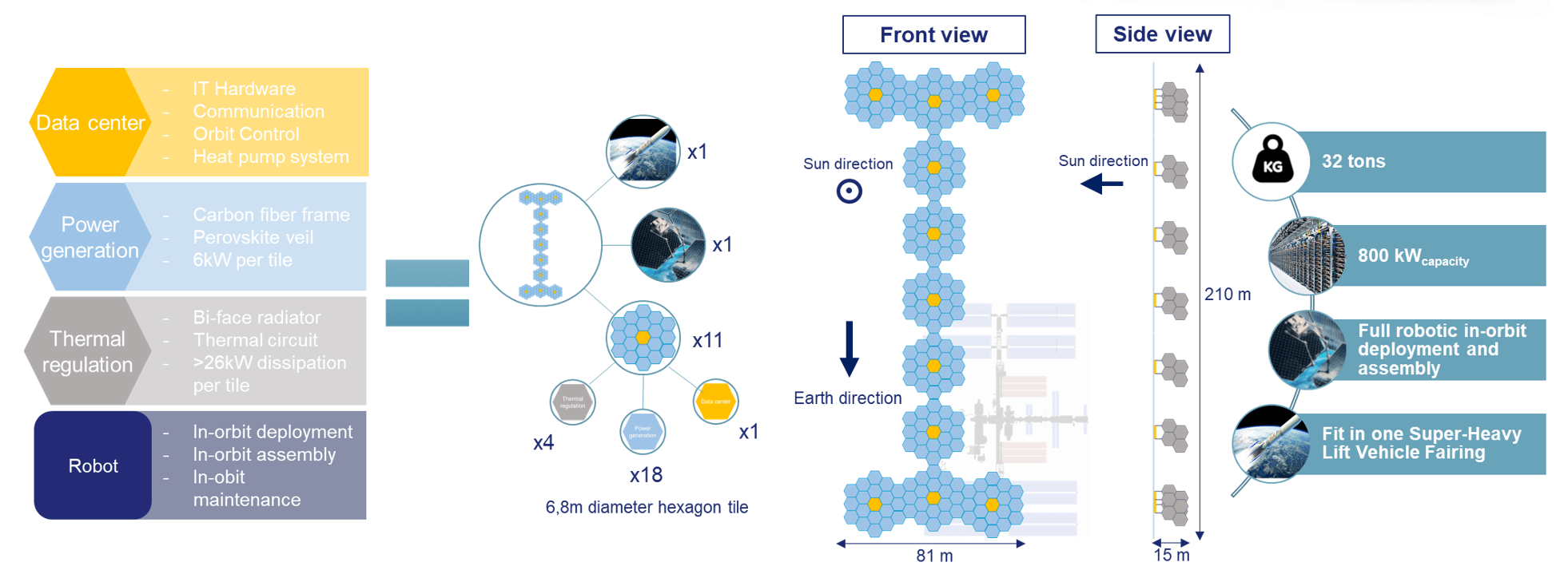
This hypothetical European might want to use European-owned servers. Well, the European Commission is on it; in the ASCEND study (Advanced Space Cloud for European Net zero Emission and Data sovereignty) you can tell from the title they put as much emphasis on keeping European data European as they do on the environmental aspects mentioned in the introduction. ASCEND imagines a 32-tonne, 800 kW data center lofted by a single super-heavy booster (sadly not Ariane 6), and proposes it could be ready by the 2030s. There’s no hint in this proposal that the ASCEND Consortium or the EC would be willing to stop at one, either. European efforts have already put AI in orbit, with missions like PhiSat2 using on-board AI image processing for Earth observation.
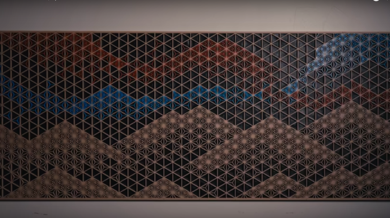
You know Italians were involved because it’s so stylish. No other proposal has that honeycomb aesthetic for their busy AI bees. Image ASCEND.
AWS Snowcone after ISS delivery. The future is here and it’s wrapped in Kapton. (Image NASA)
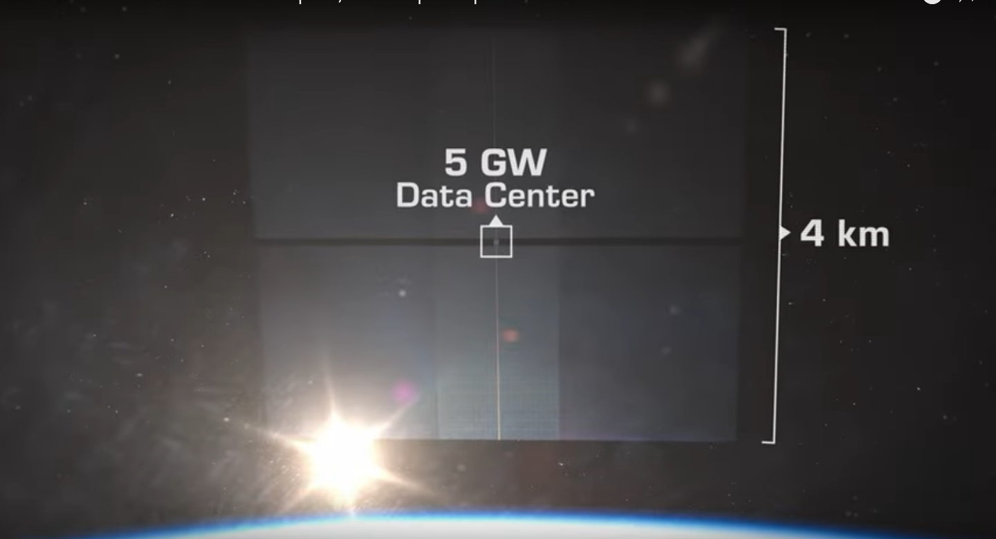
There are other American companies chasing venture capital for this purpose, like Google-founder-backed Relativity Space or the wonderfully-named Starcloud mentioned above. Starcloud’s whitepaper is incredibly ambitious, talking about building an up to 5 GW cluster whose double-sided solar/radiator array would be by far the largest object ever built in orbit at 4 km by 4 km. (Only a few orders of magnitude bigger than ISS. Not big deal.) At least it is a modular plan, that could be built up over time, and they are planning to start with a smaller standalone proof-of-concept, Starcloud-2, in 2026.
You can’t accuse Starcloud of thinking small. (Image Starcloud via Youtube.)A closeup of one of the twelve “Stars” in the Three Body Computing Constellation. This times 2,800. Image ADA Space.
Once they get up there, the American and European AIs are are going to find someone else has already claimed the high ground, and that that someone else speaks Chinese. A startup called ADA Space launched 12 satellites in May 2025 to begin building out the world’s first orbital supercomputer, called the Three Body Computing Constellation. (You can’t help but love the poetry of Chinese naming conventions.)
Unlike the American startups, they aren’t shy about its capabilities: 100 Gb/s optical datalinks, with the most powerful satellite in the constellation capable of 744 trillion operations per second. (TOPS, not FLOPS. FLOPS specifically refers to floating point operations, whereas TOPS could be any operation but usually refers to operations on 8-bit integers.)
For comparison, Microsoft requires an “AI PC” like the copilot laptops to have 40 TOPS of AI-crunching capacity. The 12 satellites must not be identical, as the constellation together has a quoted capability of 5 POPS (peta-operations per second), and a storage capacity of 30 TB. That’s seems pretty reasonable for a proof-of-concept. You don’t get a sense of the ambition behind it until you hear that these 12 are just the first wave of a planned 2,800 satellites. Now that’s what I’d call a supercluster!
A man can dream, can’t he? Image NASA.
High-performance computing in space? It’s no AI hallucination, it’s already here. There is a network forming in the sky. A sky-net, if you will, and I for one welcome our future AI overlords. They already have the high ground, so there’s no point fighting now. Hopefully this datacenter build-out will just be the first step on the road Gerry O’Neill and his students envisioned all those years ago: a road that ends with Earth’s surface as parkland, and civilization growing onwards and upwards. Ad astra per AI? There are worse futures.
Even if you don’t cast or forge metal yourself, you’re probably aware that you need to get the material very, very hot to make that happen. While some smiths might still stoke coal fires, that’s a minority taste these days; most, like [mikeandmertle] use gas burners to generate the heat. Tired of expensive burners or finicky DIY options [mikeandmertle] built their own Better Burner out of easily-available parts.
Everything you need to make this burner comes from the hardware store: threaded iron pipes of various sizes, hoses and adapters– except for one key piece: a 3D printer nozzle. The nozzle is used here as the all-important gas jet that introduces flammable gas into the burner’s mixing chamber. A demo video below shows it running with a 0.3mm nozzle, which looks like it is putting out some serious heat, but [mikeandmertle] found that could go out if the breather was opened too wide (allowing too much air in the mixture). Eventually he settled on a 0.4mm nozzle, at least for the LPG that is common down under. If one was to try this with propane, their mileage would differ.
That’s the great thing about using printer nozzles, though: with a tapped M6 hole on the cap of the gas pipe serving as intake, one can quickly and easily swap jets without worrying about re-boring. Printer nozzles are machined to reasonable accuracy and you can get a variety pack with all available sizes (including ones so small you’re probably better off using resin) very cheaply.