It’s fair to say that QR codes are a technology that has finally come of age. A decade or more ago they were a little over-hyped and sometimes used in inappropriate or pointless ways, but now they are an accepted and useful part of life.
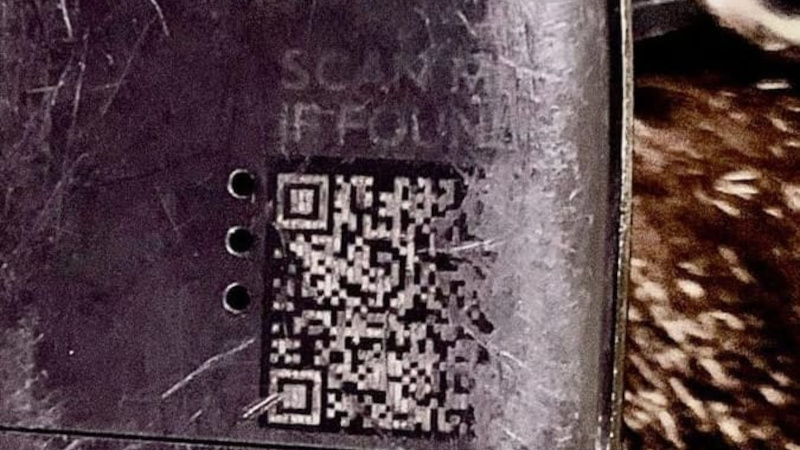
They’re not without their faults though, one of which is that despite four increasingly redundant levels of error correction, there comes a point at which a degraded QR code can no longer be read. [HumanQR] is soliciting these broken QR codes for research purposes and inclusion in an eventual open-source database, and they’ll even have a shot at repairing your submissions for you.
It’s a problem inherent to all digital media, that once the limit of whatever error correction they contain has been reached, they arrive at a cliff-edge at which they go immediately from readability to non readability. The example given in the linked article is a locator tag on a stray cat, it had been rubbed away in part. Improving its contrast, sharply defining its edges, and improving the definition of its fiducials was able to revive it, we hope leading to the cat being returned home.
The idea is that by studying enough damaged codes it should be possible to identify the means by which they become degraded, and perhaps come up with a way to inform some repair software. Meanwhile if you are interested, you might want to learn more about how they work, the hard way.
LTSpice is a tool that every electronics nerd should have at least a basic knowledge of. Those of us who work professionally in the analog and power worlds rely heavily on the validity of our simulations. It’s one of the basic skills taught at college, and essential to truly understand how a circuit behaves. [Mano] has quite a collection of videos about the tool, and here is a great video explanation of how a bootstrap circuit works, enabling a high-side driver to work in the context of driving a simple buck converter. However, before understanding what a bootstrap is, we need to talk a little theory.
Bootstrap circuits are very common when NMOS (or NPN) devices are used on the high side of a switching circuit, such as a half-bridge (and by extension, a full bridge) used to drive a motor or pump current into a power supply.
A simple half-bridge driving illustrates the high-side NMOS driving problem.
From a simplistic viewpoint, due to the apparent symmetry, you’d want to have an NMOS device at the bottom and expect a PMOS device to be at the top. However, PMOS and PNP devices are weaker, rarer and more expensive than NMOS, which is all down to the device physics; simply put, the hole mobility in silicon and most other semiconductors is much lower than the electron mobility, which results in much less current. Hence, NMOS and NPN are predominant in power circuits.
As some will be aware, to drive a high-side switching transistor, such as an NPN bipolar or an NMOS device, the source end will not be at ground, but will be tied to the switching node, which for a power supply is the output voltage. You need a way to drive the gate voltage in excess of the source or emitter end by at least the threshold voltage. This is necessary to get the device to fully turn on, to give the lowest resistance, and to cause the least power dissipation. But how do you get from the logic-level PWM control waveform to what the gate needs to switch correctly?
The answer is to use a so-called bootstrap capacitor. The idea is simple enough: during one half of the driving waveform, the capacitor is charged to some fixed voltage with respect to ground, since one end of the capacitor will be grounded periodically. On the other half cycle, the previously grounded end, jumps up to the output voltage (the source end of the high side transistor) which boosts the other side of the capacitor in excess of the source (because it got charged already) providing a temporary high-voltage floating supply than can be used to drive the high-side gate, and reliably switch on the transistor. [Mano] explains it much better in a practical scenario in the video below, but now you get the why and how of the technique.
The world’s militaries have always been at the forefront of communications technology. From trumpets and drums to signal flags and semaphores, anything that allows a military commander to relay orders to troops in the field quickly or call for reinforcements was quickly seized upon and optimized. So once radio was invented, it’s little wonder how quickly military commanders capitalized on it for field communications.
Radiotelegraph systems began showing up as early as the First World War, but World War II was the first real radio war, with every belligerent taking full advantage of the latest radio technology. Chief among these developments was the ability of signals in the high-frequency (HF) bands to reflect off the ionosphere and propagate around the world, an important capability when prosecuting a global war.
But not long after, in the less kinetic but equally dangerous Cold War period, military planners began to see the need to move more information around than HF radio could support while still being able to do it over the horizon. What they needed was the higher bandwidth of the higher frequencies, but to somehow bend the signals around the curvature of the Earth. What they came up with was a fascinating application of practical physics: meteor burst communications.
Blame It on Shannon
In practical terms, a radio signal that can carry enough information to be useful for digital communications while still being able to propagate long distances is a bit of a paradox. You can thank Claude Shannon for that, after he developed the idea of channel capacity from the earlier work of Harry Nyquist and Ralph Hartley. The resulting Hartley-Shannon Theorem states that the bit rate of a channel in a noisy environment is directly related to the bandwidth of the channel. In other words, the more data you want to stuff down a channel, the higher the frequency needs to be.
Unfortunately, that runs afoul of the physics of ionospheric propagation. Thanks to the physics of the interaction between radio waves and the charged particles between about 50 km and 600 km above the ground, the maximum frequency that can be reflected back toward the ground is about 30 MHz, which is the upper end of the HF band. Beyond that is the very-high frequency (VHF) band from 30 MHz to 300 MHz, which has enough bandwidth for an effective data channel but to which the ionosphere is essentially transparent.
Luckily, the ionosphere isn’t the only thing capable of redirecting radio waves. Back in the 1920s, Japanese physicist Hantaro Nagaoka observed that the ionospheric propagation of shortwave radio signals would change a bit during periods of high meteoric activity. That discovery largely remained dormant until after World War II, when researchers picked up on Nagoka’s work and looked into the mechanism behind his observations.
Every day, the Earth sweeps up a huge number of meteoroids; estimates range from a million to ten billion. Most of those are very small, on the order of a few nanograms, with a few good-sized chunks in the tens of kilograms range mixed in. But the ones that end up being most interesting for communications purposes are the particles in the milligram range, in part because there are about 100 million such collisions on average every day, but also because they tend to vaporize in the E-level of the ionosphere, between 80 and 120 km above the surface. The air at that altitude is dense enough to turn the incoming cosmic debris into a long, skinny trail of ions, but thin enough that the free electrons take a while to recombine into neutral atoms. It’s a short time — anywhere between 500 milliseconds to a few seconds — but it’s long enough to be useful.
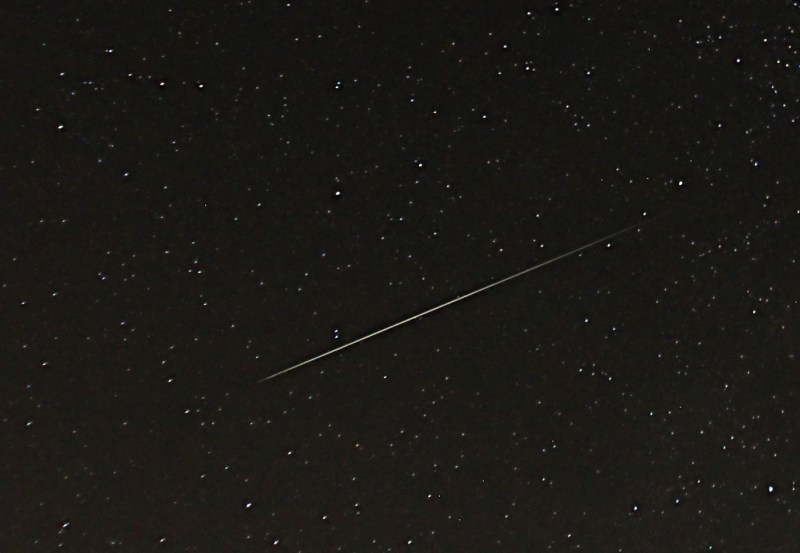
A meteor trail from the annual Perseid shower, which peaks in early August. This is probably a bit larger than the optimum for MBC, but beautiful nonetheless. Source: John Flannery, CC BY-ND 2.0.
The other aspect of meteor trails formed at these altitudes that makes them useful for communications is their relative reflectivity. The E-layer of the ionosphere normally has on the order of 107 electrons per cubic meter, a density that tends to refract radio waves below about 20 MHz. But meteor trails at this altitude can have densities as high as 1011 to 1012 electrons/m3. This makes the trails highly reflective to radio waves, especially at the higher frequencies of the VHF band.
In addition to the short-lived nature of meteor trails, daily and seasonal variations in the number of meteors complicate their utility for communications. The rotation of the Earth on its axis accounts for the diurnal variation, which tends to peak around dawn local time every day as the planet’s rotation and orbit are going in the same direction and the number of collisions increases. Seasonal variations occur because of the tilt of Earth’s axis relative to the plane of the ecliptic, where most meteoroids are concentrated. More collisions occur when the Earth’s axis is pointed in the direction of travel around the Sun, which is the second half of the year for the northern hemisphere.
Learning to Burst
Building a practical system that leverages these highly reflective but short-lived and variable mirrors in the sky isn’t easy, as shown by several post-war experimental systems. The first of these was attempted by the National Bureau of Standards in 1951. They set up a system between Cedar Rapids, Iowa, and Sterling, Virginia, a path length of about 1250 km. Originally built to study propagation phenomena such as forward scatter and sporadic E, the researchers noticed significant effects on their tests by meteor trails. This made them switch their focus to meteor trails, which caught the attention of the US Air Force. They were in the market for a four-channel continuous teletype link to their base in Thule, Greenland. They got it, but only just barely, thanks to the limited technology of the time. The NBS system also used the Iowa to Virginia system to study higher data rates by pointing highly directional rhombic antennas at each end of the connection at the same small patch of sky. They managed a whopping data rate of 3,200 bits per second with this system, but only for the second or so that a meteor trail happened to appear.
The successes and failures of the NBS system made it clear that a useful system based on meteor trails would need to operate in burst mode, to jam data through the link for as long as it existed and wait for the next one. The NBS tested a burst-mode system in 1958 that used the 50-MHz band and offered a full-duplex link at 2,400 bits per second. The system used magnetic tape loops to buffer data and transmitters at both ends of the link that operated continually to probe for a path. Whenever the receiver at one end detected a sufficiently strong probe signal from the other end, the transmitter would start sending data. The Canadians got in on the MBC action with their JANET system, which had a similar dedicated probing channel and tape buffer. In 1954 they established a full-duplex teletype link between Ottawa and Nova Scotia at 1,300 bits per second with an error rate of only 1.5%
In the late 1950s, Hughes developed a single-channel air-to-ground MBC system. This was a significant development since not only had the equipment gotten small enough to install on an airplane but also because it really refined the burst-mode technology. The ground stations in the Hughes system periodically transmitted a 100-bit interrogation signal to probe for a path to the aircraft. The receiver on the ground listened for an acknowledgement from the plane, which turned the channel around and allowed the airborne transmitter to send a 100-bit data burst. The system managed a respectable 2,400 bps data rate, but suffered greatly from ground-based interference for TV stations and automotive ignition noise.
The SHAPE of Things to Come
Supreme HQ Allied Powers Europe (SHAPE), NATO’s European headquarters in the mid-60s. The COMET meteor-bounce system kept NATO commanders in touch with member-nation HQs via teletype. Source: NATO
The first major MBC system fielded during the Cold War was the Communications by Meteor Trails system, or COMET. It was used by the North Atlantic Treaty Organization (NATO) to link its far-flung outposts in member nations with Supreme Headquarters Allied Powers Europe, or SHAPE, located in Belgium. COMET took cues from the Hughes system, especially its error detection and correction scheme. COMET was a robust and effective MBC system that provided between four and eight teletype circuits depending on daily and seasonal conditions, each handling 60 words per minute.
COMET was in continuous use from the mid-1960s until well after the official end of the Cold War. By that point, secure satellite communications were nowhere near as prohibitively expensive as they had been at the beginning of the Space Age, and MBC systems became less critical to NATO. They weren’t retired, though, and COMET actually still exists, although rebranded as “Compact Over-the-Horizon Mobile Expeditionary Terminal.” These man-portable systems don’t use MBC; rather, they use high-power UHF and microwave transmitters to scatter signals off the troposphere. A small amount of the signal is reflected back to the ground, where high-gain antennas pick up the vanishingly weak signals.
Although not directly related to Cold War communications, it’s worth noting that there was a very successful MBC system fielded in the civilian space in the United States: SNOTEL. We’ve covered this system in some depth already, but briefly, it’s a network of stations in the western part of the USA with the critical job of monitoring the snowpack. A commercial MBC system connected the solar-powered monitoring stations, often in remote and rugged locations, to two different central bases. Taking advantage of diurnal meteor variations, each morning the master station would send a polling signal out to every remote, which would then send back the previous day’s data once a return path was opened. The system could collect data from 180 remote sites in just 20 minutes. It operated successfully from the mid-1970s until just recently, when pervasive cell technology and cheap satellite modems made the system obsolete.
This is a "pre-publication" version has confused a few copyright law experts. It seems that the office released this because of numerous inquiries from members of Congress.
But making commercial use of vast troves of copyrighted works to produce expressive content that competes with them in existing markets, especially where this is accomplished through illegal access, goes beyond established fair use boundaries.
I’ve been spending a lot of time with HiDream illustration LoRAs, but the last couple nights I’ve started digging into photorealistic ones. This LoRA is based on some 1980s photography and still frames from random 80s films.
After a lot of trial and error with training setup and learning to spot over/undertraining, I’m finally starting to see the style come through.
Now I’m running into what feels like a ceiling with photorealism—whether I’m using a LoRA or not. Whenever there’s anything complicated like chains, necklaces, or detailed patterns, the model seems to give up early in the diffusion process and starts hallucinating stuff.
These were made using deis/sgm_uniform with dpm_2/beta in three passes...some samplers work better than others but never as consistently as with Flux. I’ve been using that 3 pass method for a while, especially with Flux (even posted a workflow about it back then), and it usually worked great.
I know latent upscaling will always be a little unpredictable but the visual gibberish comes through even without upscaling. I feel like images need at least two passes with HiDream or they're too smooth or unfinished in general.
I’m wondering if anyone else is experimenting with photorealistic LoRA training or upscaling — are you running into the same frustrations?
Feels like I’m right on the edge of something that works and looks good, but it’s always just a bit off and I can’t figure out why. There's like an unappealing digital noise in complex patterns and textures that I'm seeing in a lot of photo styles with this model in posts from other users too. Doesn't seem like a lot of people are sharing much about training or diffusion with this one and it's a bummer because I'd really like to see this model take off.
Has anyone here tried using AI tools that let you virtually change outfits in photos? Which ones have the most realistic results? Are there any that accurately handle different body types and poses? What about pricing - are any of the good ones available for free or with reasonable subscription costs? Would you actually use these for online shopping decisions, or are they just fun to play with?
The files attached to the article include 8 XY plots. Each of the plots begins with a control image, and then has 60 tests. This makes for 480 artist tags from danbooru tested. I wanted to highlight a variety of character types, lighting, and styles. The plots came out way too big to upload here, so they're available to review in the attachments, of the linked article. I've also included an image which puts all 480 tests on the same page. Additionally, there's a text file for you to use in wildcards with the artists used in this tests is included.
model: BarcNoobMix v2.0 sampler: euler a, normal steps: 20 cfg: 5.5 seed: 88662244555500 negatives: 3d, cgi, lowres, blurry, monochrome. ((watermark, text, signature, name, logo)). bad anatomy, bad artist, bad hands, extra digits, bad eye, disembodied, disfigured, malformed. nudity.
Prompt 1:
(artist:__:1.3), solo, male focus, three quarters profile, dutch angle, cowboy shot, (shinra kusakabe, en'en no shouboutai), 1boy, sharp teeth, red eyes, pink eyes, black hair, short hair, linea alba, shirtless, black firefighter uniform jumpsuit pull, open black firefighter uniform jumpsuit, blue glowing reflective tape. (flame motif background, dark, dramatic lighting)
(artist:__:1.3), solo, from above, perspective, dutch angle, cowboy shot, (souryuu asuka langley, neon genesis evangelion), 1girl, blue eyes, hair between eyes, long hair, orange hair, two side up, medium breasts, plugsuit, plugsuit, pilot suit, red bodysuit. (halftone background, watercolor background, stippling)
Prompt 4:
(artist:__:1.3), solo, profile, medium shot, (monika (doki doki literature club)), brown hair, very long hair, ponytail, sidelocks, white hair bow, white hair ribbon, panic, (), naked apron, medium breasts, sideboob, convenient censoring, hair censor, farmhouse kitchen, stove, cast iron skillet, bad at cooking, charred food, smoke, watercolor smoke, sunrise. (rough sketch, thick lines, watercolor texture:1.35)
NVIDIA can bring to us the 3d motion capture quality that we only can achieve with expensive 3d motion tracking suits! open they realease to open source community!
I'm still pretty new to Stable Diffusion and just getting the hang of ComfyUI (loving the node-based workflow so far!). I've been browsing CivitAI and other sites, but it's kinda overwhelming with how many models are out there.
So I thought I'd ask the pros: What are your favorite models to use with ComfyUI and why? Whether you're into hyper-realism, stylized anime, fantasy art, or something niche—I’d love to hear it.
A few things I’d love to know:
Model name + where to find it
What it’s best for (realism, anime, etc.)
Why you personally like it
Any tips for getting the best results with it in ComfyUI?
I’m especially interested in hearing what you’re using for portraits, characters, and cool styles. Bonus points if you’ve got example images or a quick workflow to share 😄
Thanks in advance for helping a noob out. You guys are awesome
I've been dealing with the style transfer from anime character to realism for a while and it been constantly bugging me how the small details often lose during a style transition. So, I decide to get a chance with doing upscale to get as much detail out as I could then I've hit with another reality wall: most upscaling method are extremely slow, still lack tons of details, huge vae decode and use custom nodes/models that are very difficult to improvise on.
Up until last week, I've try to figure out what could possibly be best method to upscale and avoiding as much problem I got above and here I have it. Just upscale, segments them to have some overlap, refine each segments like normal and blend the pixel between upscaled frames. And my gosh it works really wonder.
Right now most of my testing are SDXL since there still tons of finetune SDXL out thereand it doesn't help that I stuck with 6800XT. The detail would be even better with Flux/Hidream, although may need some change with the tagging method (currently using booru tag for each segments) to help with long prompts. Video may also work too but most likely need a complicate loop to keep bunch of frames together. But I figure it probably just better release workflow to everyone so people can find out better way doing it.
Just focus on the left side of workflow for all config and noise tuning. The 9 middle groups are just bunch of calculation for cropping segments and mask for blending. The final Exodiac combo is at the right.


![[link]](https://i.redd.it/pvlab0f0j90f1.jpeg)
![[link]](https://i.redd.it/8d9abijqo90f1.png)
![[link]](https://i.redd.it/icvsug5gxc0f1.png)