Vista Normal

Hay nuevos artículos disponibles. Pincha para refrescar la página.
Ayer — 16 Septiembre 2024Salida Principal

Usagi Electric’s Paper Tape Reader is Ready to Hop With the Tube Computer

Por: Maya Posch
16 Septiembre 2024 at 08:00

After previously working out a suitable approach to create a period-correct paper tape reader for his tube-based, MC14500B processor-inspired computer, [David Lovett] over at the Usagi Electric farm is back with a video on how he made a working tape reader.

The assembled paper tape reader as seen from the front with tape inserted. (Credit: David Lovett, Usage Electric, YouTube)

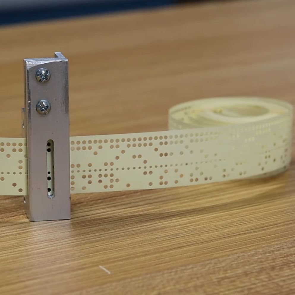
The tape reader’s purpose is to feed data into the tube-based computer, which for this computer system with its lack of storage memory means that the instructions are fed into the system directly, with the tape also providing the clock signal with a constant row of holes in the tape.

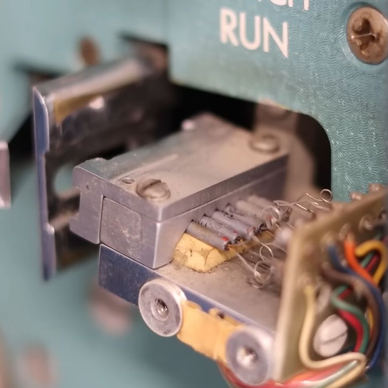
Starting the tape reader build, [David] opted to mill the structural part out of aluminum, which is where a lot of machining relearning takes place. Ultimately he got the parts machined to the paper design specs, with v-grooves for the photodiodes to fit into and a piece to clamp them down. On top of this is placed a part with holes that line up with the photodiodes.

Another alignment piece is added to hold the tape down on the reader while letting light through onto the tape via a slot. After a test assembly [David] was dismayed that due to tolerance issues he cracked two photodiodes within the v-groove clamp, which was a hard lesson with these expensive (and rare) photodiodes.

Although tolerances were somewhat off, [David] is confident that this aluminum machined reader will work once he has it mounted up. Feeding the tape is a problem that is still to be solved.  [David] is looking for ideas and suggestions for a good approach within the limitations that he’s working with. At the video’s end, he mentions learning FreeCAD and 3D printing parts in the future.  That would probably not be period-correct in this situation, but might be something he could get away with for some applications within the retrocomputing space.

We covered the first video and the thought process behind picking small (1.8 mm diameter) photodiodes as a period-correct tape hole sensor for a 1950s-era computing system, like the 1950s Bendix G-15 that [David] is currently restoring.

AnteayerSalida Principal

Building a Paper Tape Reader To Read Bytes

Por: Maya Posch
19 Agosto 2024 at 11:00

Over at the [Usagi Electric] farm, [David Lovett]’s custom 1-bit, vacuum tube-based computer (UEVTC for short) has been coming along well the past years, matching and exceeding the Motorola MC14500B 1-bit industrial control unit (ICU) that it is heavily inspired by. What is still missing, however, is a faster way to get data into the computer than manually toggling switches. The obvious choice is to make a (punched) paper tape reader, but how does one go about this, and what options exist here? With a few historical examples as reference and the tape reader on the impressive 1950s Bendix G-15 which [David] happens to have lounging around, [David] takes us in a new video through the spiraling complexity of what at first glance seems like a simple engineering challenge.

Photodiodes in the tape reader of the Bendix G-15. (Credit: David Lovett, Usagi Electric)

Punched paper tape saw significant use alongside punched paper cards and magnetic tape, and despite their low bit density, if acid-free paper (or e.g. mylar) is used, rolls of paper tape should remain readable for many decades. So how to read these perforations in the paper? This can be done mechanically, or optically, with in both case the feedrate an important consideration. Right off the bat the idea of a mechanical reader was tossed out due to tape wear, with [David] digging into his stack of photodetector tubes. After looking at a few rather clunky approaches involving such tubes, the photodiodes in the Bendix G-15’s tape reader were instead used as inspiration for a design. These are 1.8 mm diameter photodiodes, which aren’t super common, but have the nice property that they align exactly with the holes in the paper tape.

This left building a proof-of-concept on a breadboard with some incandescent bulbs and one of the photodiode to demonstrate that a valid logic signal could be produced. This turned out to be the case, clearing the construction of the actual tape reader, which will feature in upcoming videos.

❌
❌