Building a Discrete 14-Bit String DAC
How easy is it to build your own Digital to Analog Converter (DAC)? Although you can readily purchase a wide variety of DACs these days, building your own can be very instructive, as the [Sine Lab] on YouTube explores in a recent video with the construction of a discrete 14-bit DAC. First there are the different architectures you can pick for a DAC, which range from R-2R (resistor ladder) to delta-sigma versions, each having its own level of complexity and providing different response times, accuracy and other characteristics.
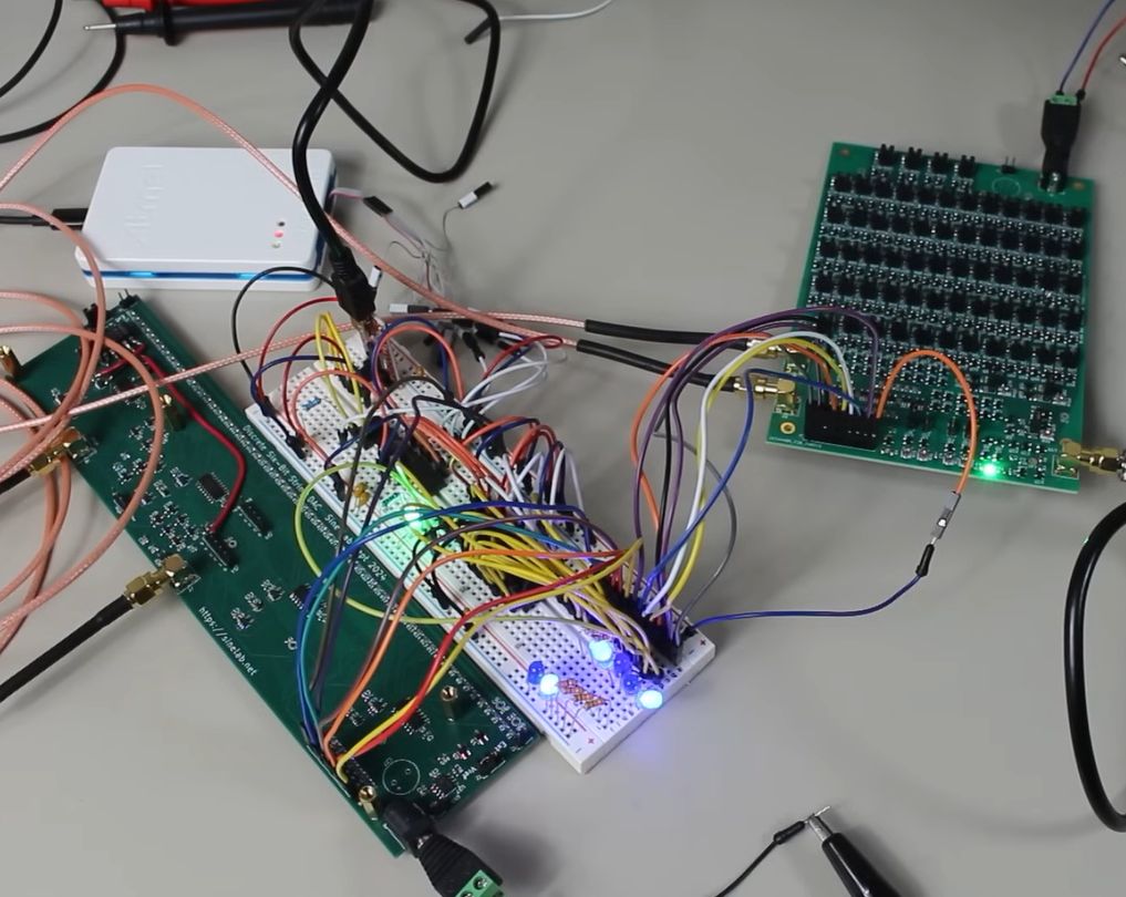
The architecture that the [Sine Lab] picked was a String DAC with interpolator. The String type DAC has the advantage of having inherently monotonic output voltage and better switching-induced glitch performance than the R-2R DAC. At its core it still uses resistors and switches (transistors), with the latter summing up the input digital value. This makes adding more bits to the DAC as easy as adding more of these same resistors and switches, the only question is how many. In the case of a String DAC that’d be 2N, which implies that you want to use multiple strings, as in the above graphic.
Scaling this up to 16-bit would thus entail 65,536 resistors/switches in the naive approach, or with 2 8-bit strings 513 switches, 512 resistors and 2 buffers. In the actual design in the video both MOSFETs and 74HCT4051 multiplexers were used, which also necessitated creating two buses per string to help with the input decoding. This is the part where things get serious in the video, but the reasoning for each change and addition is explained clearly as the full 6-bit DAC with interpolator is being designed and built.
One big issue with discrete DACs comes when you have to find matching MOSFETs and similar, which is where LSI DACs are generally significantly more precise. Even so, this discrete design came pretty close to a commercial offering, which is pretty impressive.