Ethernet From First Principles
For someone programming in a high-level language like Python, or even for people who interact primarily with their operating system and the software running on it, it can seem like the computer hardware is largely divorced from the work. Yes, the computer has to be physically present to do something like write a Hackaday article, but most of us will not understand the Assembly language, machine code, or transistor layout well enough to build up to what makes a browser run. [Francis Stokes] is a different breed, though, continually probing these mysterious low-level regions of our computerized world where he was recently able to send an Ethernet packet from scratch.
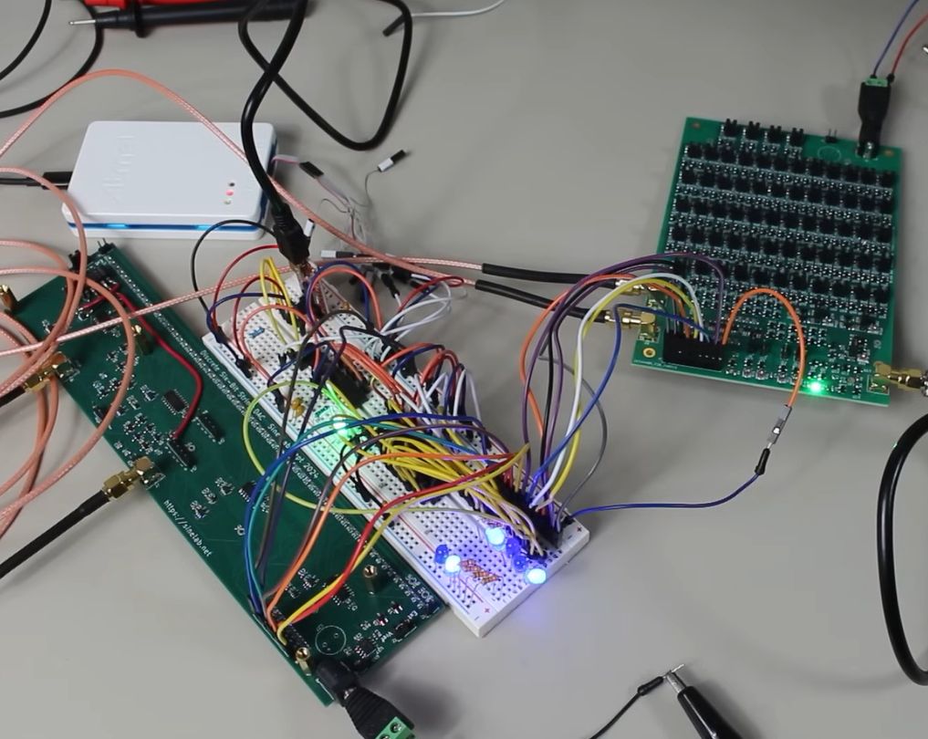
[Francis] is using an STM32F401 development board for his networking experiments, but even with this powerful microcontroller, Ethernet is much more resource-hungry than we might imagine given its ubiquity in the computing world. Most will turn to a dedicated hardware ASIC to get the Ethernet signals out on the wires rather than bit-banging the protocol, so [Francis] armed himself with a W5100 chip to handle this complex task. Since the W5100 was on a board meant for an Arduino, there were a few kinks to work out, including soldering some wires to the chip, and then there were a few more issues with the signaling, including a bug in the code, which was writing too many times to the same memory, causing the received packet to be enormous while also completely full of garbage.
In the end, [Francis] was able to remove all of the bugs from his code, reliably send an Ethernet packet from his development board, and decode it on a computer. This is an excellent deep dive into the world of signalling and networking from the bottom up. He’s done plenty of these types of investigations before as well, including developing his own AES cryptography from scratch.
We’ve looked deeply into Ethernet, too. You can even make it work on an FPGA.