Vista Normal

Hay nuevos artículos disponibles. Pincha para refrescar la página.
AnteayerSalida Principal

About Right

18 Mayo 2024 at 14:00

I really enjoyed reading Anne Ogborn’s piece on making simple DIY measurement devices for physical quantities like force, power, and torque. It is full of food for thought, if you’re building something small with motors and need to figure out how to spec them out.

A Push Stick

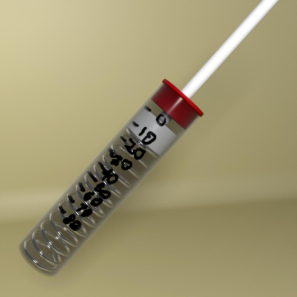
Aside from a few good examples, what I really took home from this piece is how easy it can be to take approximate measurements. Take the push stick, which is a spring-loaded plunger in a transparent barrel. You use it to measure force by, well, squeezing the spring and reading off how far it deflects. That’s obvious, but the real trick is in calibration by pushing it into a weighing scale and marking divisions on the barrel. That quickly and easily turns “it’s pressing this hard” into an actual numerical force measurement.

The accuracy and precision of the push stick are limited by the quality of your scale and the fineness of the pen tip that you use to mark the barrel. But when you’re just looking to choose among two servo motors, this kind of seat-of-the-pants measure is more than enough to buy the right part. Almost any actual measurement is better than a wild-ass guess, so don’t hold yourself to outrageous standards or think that improvised quantitative measurement devices aren’t going to get the job done.

Al Williams quoted a teacher of his as saying that the soul of metrology is “taking something you know and using it to find something you don’t know”, and that sums up this piece nicely. But it’s also almost a hacker manifesto: “take something you can do and use it to do something that you can’t (yet)”.

Got any good measurement hacks you’d like to share?

This article is part of the Hackaday.com newsletter, delivered every seven days for each of the last 200+ weeks. It also includes our favorite articles from the last seven days that you can see on the web version of the newsletter. Want this type of article to hit your inbox every Friday morning? You should sign up!

Flexures Keep This Printed Displacement Sensor In Line

18 Mayo 2024 at 11:00

When the job at hand is measuring something with micron-range precision, thoughts generally turn to a tool with a Mitutoyo or Starrett nameplate. But with a clever design and a little electronics know-how, it turns out you can 3D print a displacement sensor for measuring in the micron range for only about $10.

While the tool that [BubsBuilds] came up with isn’t as compact as a dial indicator and probably won’t win any industrial design awards, that doesn’t detract from its usefulness. And unlike a dial indicator — at least the analog type — this sensor outputs an easily digitized signal. That comes courtesy of a simple opto-interrupter sensor, which measures the position of a fine blade within its field of view. The blade is attached to a flexure that constrains its movement to a single plane; the other end of the flexure has a steel ball acting as a stylus. In use, any displacement of the stylus results in more or less light being received by the phototransistor in the opto-interrupter; the greater the deflection, the less light and the lower the current through the transistor. In addition to the sensor itself, [Bub] printed a calibration jig that allows precision gauge blocks or simple feeler gauges to be inserted in front of the stylus. The voltage across the emitter resistor for these known displacements is then used to create a calibration curve.

[Bub] says he’s getting 5-micron repeatability with careful calibration and multiple measurements of each gauge block, which seems pretty impressive to us. If you don’t need the digital output, this compliant mechanism dial indicator might be helpful too.

Thanks to [Bub]’s friend [Ethan] for the tip.

❌
❌