Modern fertilizer manufacturing uses the Haber-Bosch and Ostwald processes to fix aerial nitrogen as ammonia, then oxidize the ammonia to nitric acid. Having already created a Haber-Bosch reactor for ammonia production, [Markus Bindhammer] took the obvious next step and created an Ostwald reactor to make nitric acid.
[Markus]’s first step was to build a sturdy frame for his apparatus, since most inexpensive lab stands are light and tip over easily – not a good trait in the best of times, but particularly undesirable when working with nitrogen dioxide and nitric acid. Instead, [Markus] built a frame out of aluminium extrusion, T-nuts, threaded rods, pipe clamps, and a few cut pieces of aluminium.
Once the frame was built, [Markus] mounted a section of quartz glass tubing above a gas burner intended for camping, and connected the output of the quartz tube to a gas washing bottle. The high-temperature resistant quartz tube held a mixture of alumina and platinum wool (as we’ve seen him use before), which acted as a catalyst for the oxidation of ammonia. The input to the tube was connected to a container of ammonia solution, and the output of the gas washing bottle fed into a solution of universal pH indicator. A vacuum ejector pulled a mixture of air and ammonia vapors through the whole system, and a copper wool flashback arrestor kept that mixture from having explosive side reactions.
After [Markus] started up the ejector and lit the burner, it still took a few hours of experimentation to get the conditions right. The issue seems to be that even with catalysis, ammonia won’t oxidize to nitrogen oxides at too low a temperature, and nitrogen oxides break down to nitrogen and oxygen at too high a temperature. Eventually, though, he managed to get the flow rate right and was rewarded with the tell-tale brown fumes of nitrogen dioxide in the gas washing bottle. The universal indicator also turned red, further confirming that he had made nitric acid.
Thanks to the platinum catalyst, this reactor does have the advantage of not relying on high voltages to make nitric acid. Of course, you’ll still need get ammonia somehow.
For a world covered in oceans, getting a drink of water on Planet Earth can be surprisingly tricky. Fresh water is hard to come by even on our water world, so much so that most sources are better measured in parts per million than percentages; add together every freshwater lake, river, and stream in the world, and you’d be looking at a mere 0.0066% of all the water on Earth.
Of course, what that really says is that our endowment of saltwater is truly staggering. We have over 1.3 billion cubic kilometers of the stuff, most of it easily accessible to the billion or so people who live within 10 kilometers of a coastline. Untreated, though, saltwater isn’t of much direct use to humans, since we, our domestic animals, and pretty much all our crops thirst only for water a hundred times less saline than seawater.
While nature solved the problem of desalination a long time ago, the natural water cycle turns seawater into freshwater at too slow a pace or in the wrong locations for our needs. While there are simple methods for getting the salt out of seawater, such as distillation, processing seawater on a scale that can provide even a medium-sized city with a steady source of potable water is definitely a job for Big Chemistry.
Biology Backwards
Understanding an industrial chemistry process often starts with a look at the feedstock, so what exactly is seawater? It seems pretty obvious, but seawater is actually a fairly complex solution that varies widely in composition. Seawater averages about 3.5% salinity, which means there are 35 grams of dissolved salts in every liter. The primary salt is sodium chloride, with potassium, magnesium, and calcium salts each making a tiny contribution to the overall salinity. But for purposes of acting as a feedstock for desalination, seawater can be considered a simple sodium chloride solution where sodium anions and chloride cations are almost completely dissociated. The goal of desalination is to remove those ions, leaving nothing but water behind.
While thermal desalination methods, such as distillation, are possible, they tend not to scale well to industrial levels. Thermal methods have their place, though, especially for shipboard potable water production and in cases where fuel is abundant or solar energy can be employed to heat the seawater directly. However, in most cases, industrial desalination is typically accomplished through reverse osmosis RO, which is the focus of this discussion.
In biological systems, osmosis is the process by which cells maintain equilibrium in terms of concentration of solutes relative to the environment. The classic example is red blood cells, which if placed in distilled water will quickly burst. That’s because water from the environment, which has a low concentration of solutes, rushes across the semi-permeable cell membrane in an attempt to dilute the solutes inside the cell. All that water rushing into the cell swells it until the membrane can’t take the pressure, resulting in hemolysis. Conversely, a blood cell dropped into a concentrated salt solution will shrink and wrinkle, or crenellate, as the water inside rushes out to dilute the outside environment.
Water rushes in, water rushes out. Either way, osmosis is bad news for red blood cells. Reversing the natural osmotic flow of a solution like seawater is the key to desalination by reverse osmosis. Source: Emekadecatalyst, CC BY-SA 4.0.
Reverse osmosis is the opposite process. Rather than water naturally following a concentration gradient to equilibrium, reverse osmosis applies energy in the form of pressure to force the water molecules in a saline solution through a semipermeable membrane, leaving behind as many of the salts as possible. What exactly happens at the membrane to sort out the salt from the water is really the story, and as it turns out, we’re still not completely clear how reverse osmosis works, even though we’ve been using it to process seawater since the 1950s.
Battling Models
Up until the early 2020s, the predominant model for how reverse osmosis (RO) worked was called the “solution-diffusion” model. The SD model treated RO membranes as effectively solid barriers through which water molecules could only pass by first diffusing into the membrane from the side with the higher solute concentration. Once inside the membrane, water molecules would continue through to the other side, the permeate side, driven by a concentration gradient within the membrane. This model had several problems, but the math worked well enough to allow the construction of large-scale seawater RO plants.
The new model is called the “solution-friction” model, and it better describes what’s going on inside the membrane. Rather than seeing the membrane as a solid barrier, the SF model considers the concentrate and permeate surfaces of the membrane to communicate through a series of interconnected pores. Water is driven across the membrane not by concentration but by a pressure gradient, which drives clusters of water molecules through the pores. The friction of these clusters against the walls of the pores results in a linear pressure drop across the membrane, an effect that can be measured in the lab and for which the older SD model has no explanation.
As for the solutes in a saline solution, the SF model accounts for their exclusion from the permeate by a combination of steric hindrance (the solutes just can’t fit through the pores), the Donnan effect (which says that ions with the opposite charge of the membrane will get stuck inside it), and dielectric exclusion (the membrane presents an energy barrier that makes it hard for ions to enter it). The net result of these effects is that ions tend to get left on one side of the membrane, while water molecules can squeeze through more easily to the permeate side.
Turning these models into a practical industrial process takes a great deal of engineering. A seawater reverse osmosis or SWRO, plant obviously needs to be located close to the shore, but also needs to be close to supporting infrastructure such as a municipal water system to accept the finished product. SWRO plants also use a lot of energy, so ready access to the electrical grid is a must, as is access to shipping for the chemicals needed for pre- and post-treatment.
Pores and Pressure
Seawater processing starts with water intake. Some SWRO plants use open intakes located some distance out from the shoreline, well below the lowest possible tides and far from any potential source of contamination or damage, such a ship anchorages. Open intakes generally have grates over them to exclude large marine life and debris from entering the system. Other SWRO plants use beach well intakes, with shafts dug into the beach that extend below the water table. Seawater filters through the sand and fills the well; from there, the water is pumped into the plant. Beach wells have the advantage of using the beach sand as a natural filter for particulates and smaller sea critters, but do tend to have a lower capacity than open intakes.
Aside from the salts, seawater has plenty of other unwanted bits, all of which need to come out prior to reverse osmosis. Trash racks remove any shells, sea life, or litter that manage to get through the intakes, and sand bed filters are often used to remove smaller particulates. Ultrafiltration can be used to further clarify the seawater, and chemicals such as mild acids or bases are often used to dissolve inorganic scale and biofilms. Surfactants are often added to the feedstock, too, to break up heavy organic materials.
By the time pretreatment is complete, the seawater is remarkably free from suspended particulates and silt. Pretreatment aims to reduce the turbidity of the feedstock to less than 0.5 NTUs, or nephelometric turbidity units. For context, the US Environmental Protection Agency standard for drinking water is 0.3 NTUs for 95% of the samples taken in a month. So the pretreated seawater is almost as clear as drinking water before it goes to reverse osmosis.
SWRO cartridges have membranes wound into spirals and housed in pressure vessels. Seawater under high pressure enters the membrane spiral; water molecules migrate across the membrane to a center permeate tube, leaving a reject brine that’s about twice as saline as the feedstock. Source: DuPont Water Solutions.
The heart of reverse osmosis is the membrane, and a lot of engineering goes into it. Modern RO membranes are triple-layer thin-film composites that start with a non-woven polyester support, a felt-like material that provides the mechanical strength to withstand the extreme pressures of reverse osmosis. Next comes a porous support layer, a 50 μm-thick layer of polysulfone cast directly onto the backing layer. This layer adds to the physical strength of the backing and provides a strong yet porous foundation for the active layer, a cross-linked polyamide layer about 100 to 200 nm thick. This layer is formed by interfacial polymerization, where a thin layer of liquid monomer and initiators is poured onto the polysulfone to polymerize in place.
An RO rack in a modern SWRO desalination plant. Each of the white tubes is a pressure vessel containing seven or eight RO membrane cartridges. The vessels are plumbed in parallel to increase flow through the system. Credit: Elvis Santana, via Adobe Stock.
Modern membranes can flow about 35 liters per square meter every hour, which means an SWRO plant needs to cram a lot of surface area into a little space. This is accomplished by rolling the membrane up into a spiral and inserting it into a fiberglass pressure vessel, which holds seven or eight cartridges. Seawater pumped into the vessel soaks into the backing layer to the active layer, where only the water molecules pass through and into a collection pipe at the center of the roll. The desalinated water, or permeate, exits the cartridge through the center pipe while rejected brine exits at the other end of the pressure vessel.
The pressure needed for SWRO is enormous. The natural osmotic pressure of seawater is about 27 bar (27,000 kPa), which is the pressure needed to halt the natural flow of water across a semipermeable membrane. SWRO systems must pressurize the water to at least that much plus a net driving pressure (NPD) to overcome mechanical resistance to flow through the membrane, which amounts to an additional 30 to 40 bar.
Energy Recovery
To achieve these tremendous pressures, SWRO plants use multistage centrifugal pumps driven by large, powerful electric motors, often 300 horsepower or more for large systems. The electricity needed to run those motors accounts for 60 to 80 percent of the energy costs of the typical SWRO plant, so a lot of effort is put into recovering that energy, most of which is still locked up in the high-pressure rejected brine as hydraulic energy. This energy used to be extracted by Pelton-style turbines connected to the shaft of the main pressure pump; the high-pressure brine would spin the pump shaft and reduce the mechanical load on the pump, which would reduce the electrical load. Later, the brine’s energy would be recovered by a separate turbo pump, which would boost the pressure of the feed water before it entered the main pump.
While both of these methods were capable of recovering a large percentage of the input energy, they were mechanically complex. Modern SWRO plants have mostly moved to isobaric energy recovery devices, which are mechanically simpler and require much less maintenance. Isobaric ERDs have a single moving part, a cylindrical ceramic rotor. The rotor has a series of axial holes, a little like the cylinder of an old six-shooter revolver. The rotor is inside a cylindrical housing with endcaps on each end, each with an inlet and an outlet fitting. High-pressure reject brine enters the ERD on one side while low-pressure seawater enters on the other side. The slugs of water fill the same bore in the rotor and equalize at the same pressure without much mixing thanks to the different densities of the fluids. The rotor rotates thanks to the momentum carried by the incoming water streams and inlet fittings that are slightly angled relative to the axis of the bore. When the rotor lines up with the outlet fittings in each end cap, the feed water and the brine both exit the rotor, with the feed water at a higher pressure thanks to the energy of the reject brine.
For something with only one moving part, isobaric ERDs are remarkably effective. They can extract about 98% of the energy in the reject brine, pressuring the feed water about 60% of the total needed. An SWRO plant with ERDs typically uses 5 to 6 kWh to produce a cubic meter of desalinated water; ERDs can slash that to just 2 to 3 kWh.
Isobaric energy recovery devices can recover half of the electricity used by the typical SWRO plant by using the pressure of the reject brine to pressurize the feed water. Source: Flowserve.
Finishing Up
Once the rejected brine’s energy has been recovered, it needs to be disposed of properly. This is generally done by pumping it back out into the ocean through a pipe buried in the seafloor. The outlet is located a considerable distance from the inlet and away from any ecologically sensitive areas. The brine outlet is also generally fitted with a venturi induction head, which entrains seawater from around the outlet to partially dilute the brine.
As for the permeate that comes off the RO racks, while it is almost completely desalinated and very clean, it’s still not suitable for distribution into the drinking water system. Water this clean is highly corrosive to plumbing fixtures and has an unpleasantly flat taste. To correct this, RO water is post-processed by passing it over beds of limestone chips. The RO water tends to be slightly acidic thanks to dissolved CO2, so it partially dissolves the calcium carbonate in the limestone. This raises the pH closer to neutral and adds calcium ions to the water, which increases its hardness a bit. The water also gets a final disinfection with chlorine before being released to the distribution network.
You probably do not need us to tell you that Arsenic is not healthy stuff. This wasn’t always such common knowledge, as for a time in the 19th century a chemical variously known as Paris or Emerald Green, but known to chemists as copper(II) acetoarsenite was a very popular green pigment. While this pigment is obviously not deadly on-contact, given that it’s taken 200 years to raise the alarm about these books (and it used to be used in candy (!)), arsenic is really not something you want in your system. Libraries around the world have been quarantining vintage green books ̶f̶o̶r̶ ̶f̶e̶a̶r̶ ̶b̶i̶b̶l̶i̶o̶p̶h̶i̶l̶i̶es ̶m̶i̶g̶h̶t̶ ̶b̶e̶ ̶t̶e̶m̶p̶t̶e̶d̶ ̶t̶o̶ ̶l̶i̶c̶k̶ ̶t̶h̶e̶m̶ out of an abundance of caution, but researchers at The University of St. Andrews have found a cheaper method to detect the poison pigment than XRF or Raman Spectroscopy previously employed.
The hack is simple, and in retrospect, rather obvious: using a a hand-held vis-IR spectrometer normally used by geologists for mineral ID, they analyzed the spectrum of the compound on book covers. (As an aside, Emerald Green is similar in both arsenic content and color to the mineral conichalcite, which you also should not lick.) The striking green colour obviously has a strong response in the green range of the spectrum, but other green pigments can as well. A second band in the near-infrared clinches the identification.
A custom solution was then developed, which sadly does not seem to have been documented as of yet. From the press release it sounds like they are using LEDs and photodetectors for color detection in the green and IR at least, but there might be more to it, like a hacked version of common colour sensors that put filters on the photodetectors.
While toxic books will still remain under lock and key, the hope is that with quick and easy identification tens of thousands of currently-quarantined texts that use safer green pigments can be returned to circulation.
Tip of the hat to [Jamie] for the tip off, via the BBC.
[ProjectsInFlight] has been on a mission to make his own semiconductors for about a year now, and recently shared a major step toward that goal: homemade spin-on dopants. Doping semiconductors has traditionally been extremely expensive, requiring either ion-implantation equipment or specialized chemicals for thermal diffusion. [ProjectsInFlight] wanted to use thermal diffusion doping, but first had to formulate a cheaper dopant.
Thermal diffusion doping involves placing a source of dopant atoms (phosphorus or boron in this case) on top of the chip to be doped, heating the chip, and letting the dopant atoms diffuse into the silicon. [ProjectsInFlight] used spin-on glass doping, in which an even layer of precursor chemicals is spin-coated onto the chip. Upon heating, the precursors decompose to leave behind a protective film of glass containing the dopant atoms, which diffuse out of the glass and into the silicon.
After trying a few methods to create a glass layer, [ProjectsInFlight] settled on a composition based on tetraethyl orthosilicate, which we’ve seen used before to create synthetic opals. After finding this method, all he had to do was find the optimal reaction time, heating, pH, and reactant proportions. Several months of experimentation later, he had a working solution.
After some testing, he found that he could bring silicon wafers from their original light doping to heavy doping. This is particularly impressive when you consider that his dopant is about two orders of magnitude cheaper than similar commercial products.
Of course, after doping, you still need to remove the glass layer with an oxide etchant, which we’ve covered before. If you prefer working with lasers, we’ve also seen those used for doping.
It was such an innocent purchase, a slightly grubby and scuffed grey plastic box with the word “P O L A R O I D” intriguingly printed along its top edge. For a little more than a tenner it was mine, and I’d just bought one of Edwin Land’s instant cameras. The film packs it takes are now a decade out of production, but my Polaroid 104 with its angular 1960s styling and vintage bellows mechanism has all the retro-camera-hacking appeal I need. Straight away I 3D printed an adapter and new back allowing me to use 120 roll film in it, convinced I’d discover in myself a medium format photographic genius.
But who wouldn’t become fascinated with the film it should have had when faced with such a camera? I have form on this front after all, because a similar chance purchase of a defunct-format movie camera a few years ago led me into re-creating its no-longer-manufactured cartridges. I had to know more, both about the instant photos it would have taken, and those film packs. How did they work?
A Print, Straight From The Camera
An instant photograph reveals itself. Akos Burg, courtesy of One Instant.
In conventional black-and-white photography the film is exposed to the image, and its chemistry is changed by the light where it hits the emulsion. This latent image is rolled up with all the others in the film, and later revealed in the developing process. The chemicals cause silver particles to precipitate, and the resulting image is called a negative because the silver particles make it darkest where the most light hit it. Positive prints are made by exposing a fresh piece of film or photo paper through this negative, and in turn developing it. My Polaroid camera performed this process all-in-one, and I was surprised to find that behind what must have been an immense R&D effort to perfect the recipe, just how simple the underlying process was.
My dad had a Polaroid pack film camera back in the 1970s, a big plastic affair that he used to take pictures of the things he was working on. Pack film cameras weren’t like the motorised Polaroid cameras of today with their all-in-one prints, instead they had a paper tab that you pulled to release the print, and a peel-apart system where after a time to develop, you separated the negative from the print. I remember as a youngster watching this process with fascination as the image slowly appeared on the paper, and being warned not to touch the still-wet print or negative when it was revealed. What I was looking at wasn’t a negative printing process as described in the previous paragraph but something else, one in which the unexposed silver halide compounds which make the final image are diffused onto the paper from the less-exposed areas of the negative, forming a positive image of their own when a reducing agent precipitates out their silver crystals. Understanding the subtleties of this process required a journey back to the US Patent Office in the middle of the 20th century.
It’s All In The Diffusion
The illustration from Edwin Land’s patent US2647056.
It’s in US2647056 that we find a comprehensive description of the process, and the first surprise is that the emulsion on the negative is the same as on a contemporary panchromatic black-and-white film. The developer and fixer for this emulsion are also conventional, and are contained in a gel placed in a pouch at the head of the photograph. When the exposed film is pulled out of the camera it passes through a set of rollers that rupture this pouch, and then spread the gel in a thin layer between the negative and the coated paper. This gel has two functions: it develops the negative, but over a longer period it provides a wet medium for those unexposed silver halides to diffuse through into the now-also-wet coating of the paper which will become the print. This coating contains a reducing agent, in this case a metalic sulphide, which over a further period precipitates out the silver that forms the final visible image. This is what gives Polaroid photographs their trademark slow reveal as the chemistry does its job.
I’ve just described the black and white process; the colour version uses the same diffusion mechanism but with colour emulsions and dye couplers in place of the black-and-white chemistry. Meanwhile modern one-piece instant processes from Polaroid and Fuji have addressed the problem of making the image visible from the other side of the paper, removing the need for a peel-apart negative step.
Given that the mechanism and chemistry are seemingly so simple, one might ask why we can no longer buy two-piece Polaroid pack or roll film except for limited quantities of hand-made packs from One Instant. The answer lies in the complexity of the composition, for while it’s easy to understand how it works, it remains difficult to replicate the results Polaroid managed through a huge amount of research and development over many decades. Even the Impossible Project, current holders of the Polaroid brand, faced a significant effort to completely replicate the original Polaroid versions of their products when they brought the last remaining Polaroid factory to production back in 2010 using the original Polaroid machinery. So despite it retaining a fascination among photographers, it’s unlikely that we’ll see peel-apart film for Polaroid cameras return to volume production given the small size of the potential market.
Hacking A Sixty Year Old Camera
Five minutes with a Vernier caliper and openSCAD, and this is probably the closest I’ll get to a pack film of my own.
So having understood how peel-apart pack film works and discovered what is available here in 2025, what remains for the camera hacker with a Land camera? Perhaps the simplest idea would be to buy one of those One Instant packs, and use it as intended. But we’re hackers, so of course you will want to print that 120 conversion kit I mentioned, or find an old pack film cartridge and stick a sheet of photographic paper or even a Fuji Instax sheet in it. You’ll have to retreat to the darkroom and develop the film or run the Instax sheet through an Instax camera to see your images, but it’s a way to enjoy some retro photographic fun.
Further than that, would it be possible to load Polaroid 600 or i-Type sheets into a pack film cartridge and somehow give them paper tabs to pull through those rollers and develop them? Possibly, but all your images would be back to front. Sadly, rear-exposing Instax Wide sheets wouldn’t work either because their developer pod lies along their long side. If you were to manage loading a modern instant film sheet into a cartridge, you’d then have to master the intricate paper folding arrangement required to ensure the paper tabs for each photograph followed each other in turn. I have to admit that I’ve become fascinated by this in considering my Polaroid camera. Finally, could you make your own film? I would of course say no, but incredibly there are people who have achieved results doing just that.
My Polaroid 104 remains an interesting photographic toy, one I’ll probably try a One Instant pack in, and otherwise continue with the 3D printed back and shoot the occasional 120 roll film. If you have one too, you might find my 3D printed AAA battery adapter useful. Meanwhile it’s the cheap model without the nice rangefinder so it’ll never be worth much, so I might as well just enjoy it for what it is. And now I know a little bit more about his invention, admire Edwin Land for making it happen.
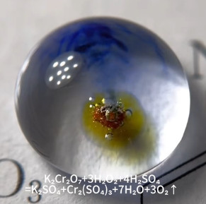
If you’re like us and you’ve been wondering where those viral videos of single water drop chemical reactions are coming from, we may have an answer. [yu3375349136], a scientist from Guangdong, has been producing some high quality microchemistry videos that are worth a watch.
While some polyglots out there won’t be phased, we appreciate the captioning for Western audiences using the elemental symbols we all know and love in addition to the Simplified Chinese. Reactions featured are typically colorful, but simple with a limited number of reagents. Being able to watch diffusion of the chemicals through the water drop and the results in the center when more than one chemical is used are mesmerizing.
We do wish there was a bit more substance to the presentation, and we’re aware not all readers will be thrilled to point their devices to Douyin (known outside of China as TikTok) to view them, but we have to admit some of the reactions are beautiful.