Vista Normal

Hay nuevos artículos disponibles. Pincha para refrescar la página.
Hoy — 24 Mayo 2025Salida Principal

LED Matrix Built For M.2 Interface

Por: Lewin Day
24 Mayo 2025 at 08:00

The M.2 slot is usually used for solid-state storage devices. However, [bitluni] had another fun idea for how to use the interface. He built an M.2 compatible LED matrix that adds a little light to your motherboard.

[bitluni] built a web tool for sending images to the matrix.
[bitluni] noted that the M.2 interface is remarkably flexible, able to offer everything from SATA connections to USB, PCI Express, and more. For this project, he elected to rely on PCI Express communication, using a WCH CH382 chip to translate from that interface to regular old serial communication.

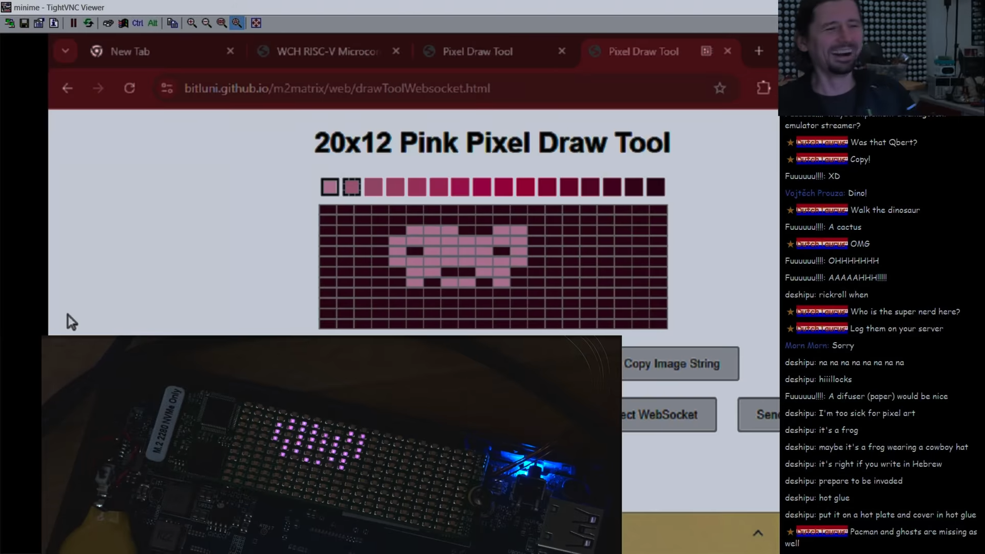
He then hooked up the serial interface to a CH32V208 microcontroller, which was tasked with driving a 12×20 monochrome LED matrix. Even better, he was even able to set the microcontroller up to make it programmable upon first plugging it into a machine, thanks to its bootloader supporting serial programming out of the box. Some teething issues required rework and modification, but soon enough, [bitluni] had the LEDs blinking with the best of them. He then built a web-based drawing tool that could send artwork over serial direct to the matrix.

While most of us are using our M.2 slots for more traditional devices, it’s neat to see this build leverage them for another use. We could imagine displays like this becoming a neat little add-on to a blingy computer build for those with a slot or two to spare. Meanwhile, if you want to learn more about M.2, we’ve dived into the topic before.

AnteayerSalida Principal

A Delay Line Memory Demo Board

Por: Lewin Day
4 Mayo 2025 at 11:00

Delay line memory is a technology from yesteryear, but it’s not been entirely forgotten. [P-Lab] has developed a demo board for delay-line memory, which shows how it worked in a very obvious way with lots of visual aids.

If you’re unfamiliar with the technology, it’s a form of memory that was used in classic computers like the Univac-I and the Olivetti Programma 101. It’s a sequential-access technology, where data is stored as pulses in some kind of medium, and read out in order. Different forms of the technology exist, such as using acoustic pulses in mercury or torsional waves passing through coiled nickel wire.

In this case, [P-Lab] built a solid state delay line using TTL ICs, capable of storing a full 64 bits of information and running at speeds of up to 150 kHz. It also features a write-queuing system to ensure bits are written at the exact correct time — the sequential-access nature of the technology means random writes and reads aren’t actually possible. The really cool thing is that [P-Lab] paired the memory with lots of LEDs to show how it works. There are lights to indicate the operation of the clock, and the read and write cycles, as well as individual LEDs indicating the status of each individual bit as they roll around the delay line. Combined with the hexadecimal readouts, it makes it easy to get to grips with this old-school way of doing things.

We’ve seen previous work from[P-Lab] in this regard using old-school core rope memory, too.

[Thanks to Giuseppe for the tip!]

RP2040 Spins Right ‘Round inside POV Display

26 Abril 2025 at 05:00

Sometimes, a flat display just won’t cut it. If you’re looking for something a little rounder, perhaps your vision could persist in in looking at [lhm0]’s rotating LED sphere RP2040 POV display.

As you might have guessed from that title, this persistence-of-vision display uses an RP2040 microcontroller as its beating (or spinning, rather) heart. An optional ESP01 provides a web interface for control. Since the whole assembly is rotating at high RPM, rather than slot in dev boards (like Pi Pico) as is often seen, [lhm0] has made custom PCBs to hold the actual SMD chips. Power is wireless, because who wants to deal with slip rings when they do not have to?

The LED-bending jig is a neat hack-within-a-hack.

[lhm0] has also bucked the current trend for individually-addressable LEDs, opting instead to address individual through-hole RGB LEDs via a 24-bit shift-register. Through the clever use of interlacing, those 64 LEDs produce a 128 line display. [lhm0] designed and printed an LED-bending jig to aid mounting the through-hole LEDs to the board at a perfect 90 degree angle.

What really takes this project the extra mile is that [lhm0] has also produced a custom binary video/image format for his display, .rs64, to encode images and video at the 128×256 format his sphere displays. That’s on github,while a seperate library hosts the firmware and KiCad files for the display itself.

This is hardly the first POV display we’ve highlighted, though admittedly it isn’t the cheapest one. There are even other spherical displays, but none of them seem to have gone to the trouble of creating a file format.

If you want to see it in action and watch construction, the video is embedded below.

Trekulator: A Reproduction of the 1977 Star Trek Themed Calculator

21 Abril 2025 at 20:00

A recent project over on Hackaday.io from [Michael Gardi] is Trekulator – Where No Maker Has Gone Before.

This is a fun build and [Michael] has done a very good job of emulating the original device. [Michael] used the Hackaday.io logging feature to log his progress. Starting in September 2024 he modeled the case, got his original hardware working, got the 7-segment display working, added support for sound, got the keypad working and mounted it, added the TFT display and mounted it, wired up the breadboard implementation, designed and implemented the PCBs, added some finishing touches, installed improved keys, and added a power socket back in March.

It is perhaps funny that where the original device used four red LEDs, [Michael] has used an entire TFT display. This would have been pure decadence by the standards of 1977. The software for the ESP32 microcontroller was fairly involved. It had to support audio, graphics, animations, keyboard input, the 7-segment display, and the actual calculations.

The calculations are done using double-precision floating-point values and eight positions on the display so this code will do weird things in some edge cases. For instance if you ask it to sum two eight digit numbers as 90,000,000 and 80,000,000, which would ordinarily sum to the nine digit value 170,000,000, the display will show you a different value instead, such as maybe 17,000,000 or 70,000,000. Why don’t you put one together and let us know what it actually does! Also, can you find any floating-point precision bugs?

This was a really fun project, thanks to [Michael] for writing it up and letting us know via the tips line!

❌
❌