Taking delivery of a new vehicle from a dealership is an emotional mixed bag. On the one hand, you’ve had to endure the sales rep’s hunger to close the deal, the tedious negotiations with the classic “Let me run that by my manager,” and the closer who tries to tack on ridiculous extras like paint sealer and ashtray protection. On the other hand, you’re finally at the end of the process, and now you get to play with the Shiny New Thing in your life while pretending it hasn’t caused your financial ruin. Wouldn’t it be nice to skip all those steps in the run-up and just cut right to the delivery? That’s been Tesla’s pitch for a while now, and they finally made good on the promise with their first self-driving delivery.
The Model Y sedan drove itself from its birthplace at the Texas Gigafactory to its new owner, a 30-minute trip that covered a variety of driving situations. The fully autonomous EV did quite well over its journey, except for at the very end, where it blatantly ignored the fire lane outside its destination and parked against the red-painted curb. While some are trying to make hay of Tesla openly flaunting the law, we strongly suspect this was a “closed course” deal, at least for that last bit of the trip. So the production team probably had permission to park there, but it’s not a good look, especially with a parking lot just a few meters to the left. But it’s pretty cool that the vehicle was on the assembly line just a half-hour before. Betcha the owner still had to pay for dealer prep and delivery, though.
How much space does a million dollars take up? According to the Federal Reserve Bank of Chicago, a million one-dollar bills will fit into a cube about 50 inches (1.27 m) on a side, and they even built one as a display for their museum. Putting aside for the moment the fact that the Federal Reserve Bank of Chicago feels that they have enough public appeal to support a museum — we’d love to see the gift shop — would a million bucks really fit into a little more than a cubic meter? Not according to Calvin Liang, who took it upon himself to determine the real number of semolians on display. To do so, he built an app called Dot Counter, which lets users count items in an image by clicking on them. It turns out that the cube holds more like $1.55 million, at least assuming there are no voids inside. He also works through the math on what it would take to make an actual million-dollar cube; turns out that the 2.53:1 aspect ratio of a dollar bill makes it tough to manage anything other than a cuboid slightly smaller than the display cube holding $1.008 million. All of that really doesn’t matter, though, since Dot Counter is sure to help us win every “Guess the number of jelly beans in the jar” contest we see.
Even for the smallest of jobs, driving a truck is a hard job. And the job just keeps getting harder as the load gets bigger, as a driver in Maryland can attest to after a bizarre accident last week during the transport of a wind turbine blade. It’s a little hard to tell exactly what happened from the published stories, and the stills from the traffic-potato aren’t much help either. But it looks like the steerable rear wheels on the mega-long trailer used to move the blade, which looks to be at least 50 meters long, decided to take the eastbound lane of I-70 while the rest of the truck was going west. The pucker factor for the driver must have been off the charts as the blade crossed the highway median. Luckily, traffic was light at 5:00 AM when the accident happened, but even still, one injury was reported, and the ensuing mayhem as the blade remained lodged across both lanes as the Monday rush started must have been one for the books.
A couple of weeks ago, we featured a story on a great collection of Telnet games and demos, some of which are so accomplished that it really blows the mind. One that didn’t make that list is this fantastic ASCII moon-phase tracker. It uses ASCII art to depict the current phase of the moon visually, and yes, you can copy and paste the characters. True, it’s web-based, which probably accounts for it not appearing on the Telnet games list, but the source code is available, so making it work over Telnet might be a fun project for someone.
And finally, we’ve heard about “Netflix and chill,” but is “NASA and chill” about to be a thing? Apparently so, since NASA+, the US space agency’s media outlet, made a deal with Netflix to offer its live programming on the streaming service. This is fantastic news for Netflix subscribers, who instead of watching live launches and such for free on YouTube can pay be the privilege of watching the same content on Netflix, complete with extra ads thrown in. That’s one giant leap for mankind right there.
In today’s episode of “AI Is Why We Can’t Have Nice Things,” we feature the Hertz Corporation and its new AI-powered rental car damage scanners. Gone are the days when an overworked human in a snappy windbreaker would give your rental return a once-over with the old Mark Ones to make sure you hadn’t messed the car up too badly. Instead, Hertz is fielding up to 100 of these “MRI scanners for cars.” The “damage discovery tool” uses cameras to capture images of the car and compares them to a model that’s apparently been trained on nothing but showroom cars. Redditors who’ve had the displeasure of being subjected to this thing report being charged egregiously high damage fees for non-existent damage. To add insult to injury, if renters want to appeal those charges, they have to argue with a chatbot first, one that offers no path to speaking with a human. While this is likely to be quite a tidy profit center for Hertz, their customers still have a vote here, and backlash will likely lead the company to adjust the model to be a bit more lenient, if not outright scrapping the system.
Have you ever picked up a flashlight and tried to shine it through your hand? You probably have; it’s just a thing you do, like the “double tap” every time you pick up a power drill. We’ve yet to find a flashlight bright enough to sufficiently outline the bones in our palm, although we’ve had some luck looking through the flesh of our fingers. While that’s pretty cool, it’s quite a bit different from shining a light directly through a human head, which was recently accomplished for the first time at the University of Glasgow. The researchers blasted a powerful pulsed laser against the skull of a volunteer with “fair skin and no hair” and managed to pick up a few photons on the other side, despite an attenuation factor of about 1018. We haven’t read the paper yet, so it’s unclear if the researchers controlled for the possibility of the flesh on the volunteer’s skull acting like a light pipe and conducting the light around the skull rather than through it, but if the laser did indeed penetrate the skull and everything within it, it’s pretty cool. Why would you do this, especially when we already have powerful light sources that can easily penetrate the skull and create exquisitely detailed images of the internal structures? Why the hell wouldn’t you?!
TIG welding aluminum is a tough process to master, and just getting to the point where you’ve got a weld you’re not too embarrassed of would be so much easier if you could just watch someone who knows what they’re doing. That’s a tall order, though, as the work area is literally a tiny pool of molten metal no more than a centimeter in diameter that’s bathed in an ultra-bright arc that’s throwing off cornea-destroying UV light. Luckily, Aaron over at 6061.com on YouTube has a fantastic new video featuring up-close and personal shots of him welding up some aluminum coupons. He captured them with a Helios high-speed welding camera, and the detail is fantastic. You can watch the weld pool forming and see the cleaning action of the AC waveform clearly. The shots make it clear exactly where and when you should dip your filler rod into the pool, the effect of moving the torch smoothly and evenly, and how contaminants can find their way into your welds. The shots make it clear what a dynamic environment the weld pool is, and why it’s so hard to control.
And finally, the title may be provocative, but “The Sensual Wrench” is a must-see video for anyone even remotely interested in tools. It’s from the New Mind channel on YouTube, and it covers the complete history of wrenches. Our biggest surprise was learning how relatively recent an invention the wrench is; it didn’t really make an appearance in anything like its modern form until the 1800s. The video covers everything from the first adjustable wrenches, including the classic “monkey” and “Crescent” patterns, through socket wrenches with all their various elaborations, right through to impact wrenches. Check it out and get you ugga-dugga on.
A lot of people complain that driving across the United States is boring. Having done the coast-to-coast trip seven times now, I can’t agree. Sure, the stretches through the Corn Belt get a little monotonous, but for someone like me who wants to know how everything works, even endless agriculture is fascinating; I love me some center-pivot irrigation.
One thing that has always attracted my attention while on these long road trips is the weigh stations that pop up along the way, particularly when you transition from one state to another. Maybe it’s just getting a chance to look at something other than wheat, but weigh stations are interesting in their own right because of everything that’s going on in these massive roadside plazas. Gone are the days of a simple pull-off with a mechanical scale that was closed far more often than it was open. Today’s weigh stations are critical infrastructure installations that are bristling with sensors to provide a multi-modal insight into the state of the trucks — and drivers — plying our increasingly crowded highways.
All About the Axles
Before diving into the nuts and bolts of weigh stations, it might be helpful to discuss the rationale behind infrastructure whose main function, at least to the casual observer, seems to be making the truck driver’s job even more challenging, not to mention less profitable. We’ve all probably sped by long lines of semi trucks queued up for the scales alongside a highway, pitying the poor drivers and wondering if the whole endeavor is worth the diesel being wasted.
The answer to that question boils down to one word: axles. In the United States, the maximum legal gross vehicle weight (GVW) for a fully loaded semi truck is typically 40 tons, although permits are issued for overweight vehicles. The typical “18-wheeler” will distribute that load over five axles, which means each axle transmits 16,000 pounds of force into the pavement, assuming an even distribution of weight across the length of the vehicle. Studies conducted in the early 1960s revealed that heavier trucks caused more damage to roadways than lighter passenger vehicles, and that the increase in damage is proportional to the fourth power of axle weight. So, keeping a close eye on truck weights is critical to protecting the highways.
Just how much damage trucks can cause to pavement is pretty alarming. Each axle of a truck creates a compression wave as it rolls along the pavement, as much as a few millimeters deep, depending on road construction and loads. The relentless cycle of compression and expansion results in pavement fatigue and cracks, which let water into the interior of the roadway. In cold weather, freeze-thaw cycles exert tremendous forces on the pavement that can tear it apart in short order. The greater the load on the truck, the more stress it puts on the roadway and the faster it wears out.
The other, perhaps more obvious reason to monitor axles passing over a highway is that they’re critical to truck safety. A truck’s axles have to support huge loads in a dynamic environment, and every component mounted to each axle, including springs, brakes, and wheels, is subject to huge forces that can lead to wear and catastrophic failure. Complete failure of an axle isn’t uncommon, and a driver can be completely unaware that a wheel has detached from a trailer and become an unguided missile bouncing down the highway. Regular inspections of the running gear on trucks and trailers are critical to avoiding these potentially catastrophic occurrences.
Ways to Weigh
The first thing you’ll likely notice when driving past one of the approximately 700 official weigh stations lining the US Interstate highway system is how much space they take up. In contrast to the relatively modest weigh stations of the past, modern weigh stations take up a lot of real estate. Most weigh stations are optimized to get the greatest number of trucks processed as quickly as possible, which means constructing multiple lanes of approach to the scale house, along with lanes that can be used by exempt vehicles to bypass inspection, and turnout lanes and parking areas for closer inspection of select vehicles.
In addition to the physical footprint of the weigh station proper, supporting infrastructure can often be seen miles in advance. Fixed signs are usually the first indication that you’re getting near a weigh station, along with electronic signboards that can be changed remotely to indicate if the weigh station is open or closed. Signs give drivers time to figure out if they need to stop at the weigh station, and to begin the process of getting into the proper lane to negotiate the exit. Most weigh stations also have a net of sensors and cameras mounted to poles and overhead structures well before the weigh station exit. These are monitored by officers in the station to spot any trucks that are trying to avoid inspections.
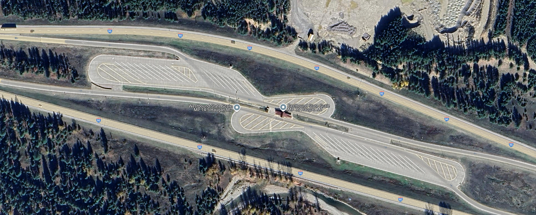
Overhead view of a median weigh station on I-90 in Haugan, Montana. Traffic from both eastbound and westbound lanes uses left exits to access the scales in the center. There are ample turnouts for parking trucks that fail one test or another. Source: Google Maps.
Most weigh stations in the US are located off the right side of the highway, as left-hand exit ramps are generally more dangerous than right exits. Still, a single weigh station located in the median of the highway can serve traffic from both directions, so the extra risk of accidents from exiting the highway to the left is often outweighed by the savings of not having to build two separate facilities. Either way, the main feature of a weigh station is the scale house, a building with large windows that offer a commanding view of the entire plaza as well as an up-close look at the trucks passing over the scales embedded in the pavement directly adjacent to the structure.
Scales at a weigh station are generally of two types: static scales, and weigh-in-motion (WIM) systems. A static scale is a large platform, called a weighbridge, set into a pit in the inspection lane, with the surface flush with the roadway. The platform floats within the pit, supported by a set of cantilevers that transmit the force exerted by the truck to electronic load cells. The signal from the load cells is cleaned up by signal conditioners before going to analog-to-digital converters and being summed and dampened by a scale controller in the scale house.
The weighbridge on a static scale is usually long enough to accommodate an entire semi tractor and trailer, which accurately weighs the entire vehicle in one measurement. The disadvantage is that the entire truck has to come to a complete stop on the weighbridge to take a measurement. Add in the time it takes for the induced motion of the weighbridge to settle, along with the time needed for the driver to make a slow approach to the scale, and each measurement can add up to significant delays for truckers.
Weigh-in-motion sensor. WIM systems measure the force exerted by each axle and calculate a total gross vehicle weight (GVW) for the truck while it passes over the sensor. The spacing between axles is also measured to ensure compliance with state laws. Source: Central Carolina Scales, Inc.
To avoid these issues, weigh-in-motion systems are often used. WIM systems use much the same equipment as the weighbridge on a static scale, although they tend to use piezoelectric sensors rather than traditional strain-gauge load cells, and usually have a platform that’s only big enough to have one axle bear on it at a time. A truck using a WIM scale remains in motion while the force exerted by each axle is measured, allowing the controller to come up with a final GVW as well as weights for each axle. While some WIM systems can measure the weight of a vehicle at highway speed, most weigh stations require trucks to keep their speed pretty slow, under five miles per hour. This is obviously for everyone’s safety, and even though the somewhat stately procession of trucks through a WIM can still plug traffic up, keeping trucks from having to come to a complete stop and set their brakes greatly increases weigh station throughput.
Another advantage of WIM systems is that the spacing between axles can be measured. The speed of the truck through the scale can be measured, usually using a pair of inductive loops embedded in the roadway around the WIM sensors. Knowing the vehicle’s speed through the scale allows the scale controller to calculate the distance between axles. Some states strictly regulate the distance between a trailer’s kingpin, which is where it attaches to the tractor, and the trailer’s first axle. Trailers that are not in compliance can be flagged and directed to a parking area to await a service truck to come by to adjust the spacing of the trailer bogie.
Keep It Moving, Buddy
A PrePass transponder reader and antenna over Interstate 10 near Pearlington, Mississippi. Trucks can bypass a weigh station if their in-cab transponder identifies them as certified. Source: Tony Webster, CC BY-SA 2.0.
Despite the increased throughput of WIM scales, there are often too many trucks trying to use a weigh station at peak times. To reduce congestion further, some states participate in automatic bypass systems. These systems, generically known as PrePass for the specific brand with the greatest market penetration, use in-cab transponders that are interrogated by transmitters mounted over the roadway well in advance of the weigh station. The transponder code is sent to PrePass for authentication, and if the truck ID comes back to a company that has gone through the PrePass certification process, a signal is sent to the transponder telling the driver to bypass the weigh station. The transponder lights a green LED in this case, which stays lit for about 15 minutes, just in case the driver gets stopped by an overzealous trooper who mistakes the truck for a scofflaw.
PrePass transponders are just one aspect of an entire suite of automatic vehicle identification (AVI) systems used in the typical modern weigh station. Most weigh stations are positively bristling with cameras, some of which are dedicated to automatic license plate recognition. These are integrated into the scale controller system and serve to associate WIM data with a specific truck, so violations can be flagged. They also help with the enforcement of traffic laws, as well as locating human traffickers, an increasingly common problem. Weigh stations also often have laser scanners mounted on bridges over the approach lanes to detect unpermitted oversized loads. Image analysis systems are also used to verify the presence and proper operation of required equipment, such a mirrors, lights, and mudflaps. Some weigh stations also have systems that can interrogate the electronic logging device inside the cab to verify that the driver isn’t in violation of hours of service laws, which dictate how long a driver can be on the road before taking breaks.
Sensors Galore
IR cameras watch for heat issues on trucks at a Kentucky weigh station. Heat signatures can be used to detect bad tires, stuck brakes, exhaust problems, and even illicit cargo. Source: Trucking Life with Shawn
Another set of sensors often found in the outer reaches of the weigh station plaza is related to the mechanical status of the truck. Infrared cameras are often used to scan for excessive heat being emitted by an axle, often a sign of worn or damaged brakes. The status of a truck’s tires can also be monitored thanks to Tire Anomaly and Classification Systems (TACS), which use in-road sensors that can analyze the contact patch of each tire while the vehicle is in motion. TACS can detect flat tires, over- and under-inflated tires, tires that are completely missing from an axle, or even mismatched tires. Any of these anomalies can cause a tire to quickly wear out and potentially self-destruct at highway speeds, resulting in catastrophic damage to surrounding traffic.
Trucks with problems are diverted by overhead signboards and direction arrows to inspection lanes. There, trained truck inspectors will closely examine the flagged problem and verify the violation. If the problem is relatively minor, like a tire inflation problem, the driver might be able to fix the issue and get back on the road quickly. Trucks that can’t be made safe immediately might have to wait for mobile service units to come fix the problem, or possibly even be taken off the road completely. Only after the vehicle is rendered road-worthy again can you keep on trucking.
We haven’t seen any projects from serial experimenter [Les Wright] for quite a while, and honestly, we were getting a little worried about that. Turns out we needn’t have fretted, as [Les] was deep into this exploration of the Pockels Effect, with pretty cool results.
If you’ll recall, [Les]’s last appearance on these pages concerned the automated creation of huge, perfect crystals of KDP, or potassium dihydrogen phosphate. KDP crystals have many interesting properties, but the focus here is on their ability to modulate light when an electrical charge is applied to the crystal. That’s the Pockels Effect, and while there are commercially available Pockels cells available for use mainly as optical switches, where’s the sport in buying when you can build?
As with most of [Les]’s projects, there are hacks galore here, but the hackiest is probably the homemade diamond wire saw. The fragile KDP crystals need to be cut before use, and rather than risk his beauties to a bandsaw or angle grinder, [Les] threw together a rig using a stepper motor and some cheap diamond-encrusted wire. The motor moves the diamond wire up and down while a weight forces the crystal against it on a moving sled. Brilliant!
The cut crystals are then polished before being mounted between conductive ITO glass and connected to a high-voltage supply. The video below shows the beautiful polarization changes induced by the electric field, as well as demonstrating how well the Pockels cell acts as an optical switch. It’s kind of neat to see a clear crystal completely block a laser just by flipping a switch.
It’s an inconvenient fact that most of Earth’s largesse of useful minerals is locked up in, under, and around a lot of rock. Our little world condensed out of the remnants of stars whose death throes cooked up almost every element in the periodic table, and in the intervening billions of years, those elements have sorted themselves out into deposits that range from the easily accessed, lying-about-on-the-ground types to those buried deep in the crust, or worse yet, those that are distributed so sparsely within a mineral matrix that it takes harvesting megatonnes of material to find just a few kilos of the stuff.
Whatever the substance of our desires, and no matter how it is associated with the rocks and minerals below our feet, almost every mining and refining effort starts with wresting vast quantities of rock from the Earth’s crust. And the easiest, cheapest, and fastest way to do that most often involves blasting. In a very real way, explosives make the world work, for without them, the minerals we need to do almost anything would be prohibitively expensive to produce, if it were possible at all. And understanding the chemistry, physics, and engineering behind blasting operations is key to understanding almost everything about Mining and Refining.
First, We Drill
For almost all of the time that we’ve been mining minerals, making big rocks into smaller rocks has been the work of strong backs and arms supplemented by the mechanical advantage of tools like picks, pry bars, and shovels. The historical record shows that early miners tried to reduce this effort with clever applications of low-energy physics, such as jamming wooden plugs into holes in the rocks and soaking them with liquid to swell the wood and exert enough force to fracture the rock, or by heating the rock with bonfires and then flooding with cold water to create thermal stress fractures. These methods, while effective, only traded effort for time, and only worked for certain types of rock.
Mining productivity got a much-needed boost in 1627 with the first recorded use of gunpowder for blasting at a gold mine in what is now Slovakia. Boreholes were stuffed with powder that was ignited by a fuse made from a powder-filled reed. The result was a pile of rubble that would have taken weeks to produce by hand, and while the speed with which the explosion achieved that result was probably much welcomed by the miners, in reality, it only shifted their efforts to drilling the boreholes, which generally took a five-man crew using sledgehammers and striker bars to pound deep holes into the rock. Replacing that manual effort with mechanical drilling was the next big advance, but it would have to wait until the Industrial Revolution harnessed the power of steam to run drills capable of boring deep holes in rock quickly and with much smaller crews.
The basic principles of rock drilling developed in the 19th century, such as rapidly spinning a hardened steel bit while exerting tremendous down-pressure and high-impulse percussion, remain applicable today, although with advancements like synthetic diamond tooling and better methods of power transmission. Modern drills for open-cast mining fall into two broad categories: overburden drills, which typically drill straight down or at a slight angle to vertical and can drill large-diameter holes over 100 meters deep, and quarry drills, which are smaller and more maneuverable rigs that can drill at any angle, even horizontally. Most drill rigs are track-driven for greater mobility over rubble-strewn surfaces, and are equipped with soundproofed, air-conditioned cabs with safety cages to protect the operator. Automation is a big part of modern rigs, with automatic leveling systems, tool changers that can select the proper bit for the rock type, and fully automated drill chain handling, including addition of drill rod to push the bit deeper into the rock. Many drill rigs even have semi-autonomous operation, where a single operator can control a fleet of rigs from a single remote control console.
Proper Prior Planning
While the use of explosives seems brutally chaotic and indiscriminate, it’s really the exact opposite. Each of the so-called “shots” in a blasting operation is a carefully controlled, highly engineered event designed to move material in a specific direction with the desired degree of fracturing, all while ensuring the safety of the miners and the facility.
To accomplish this, a blasting plan is put together by a mining engineer. The blasting plan takes into account the mechanical characteristics of the rock, the location and direction of any pre-existing fractures or faults, and proximity to any structures or hazards. Engineers also need to account for the equipment used for mucking, which is the process of removing blasted material for further processing. For instance, a wheeled loader operating on the same level, or bench, that the blasting took place on needs a different size and shape of rubble pile than an excavator or dragline operating from the bench above. The capabilities of the rock crushing machinery that’s going to be used to process the rubble also have to be accounted for in the blasting plan.
Most blasting plans define a matrix of drill holes with very specific spacing, generally with long rows and short columns. The drill plan specifies the diameter of each hole along with its depth, which usually goes a little beyond the distance to the next bench down. The mining engineer also specifies a stem height for the hole, which leaves room on top of the explosives to backfill the hole with drill tailings or gravel.
Prills and Oil
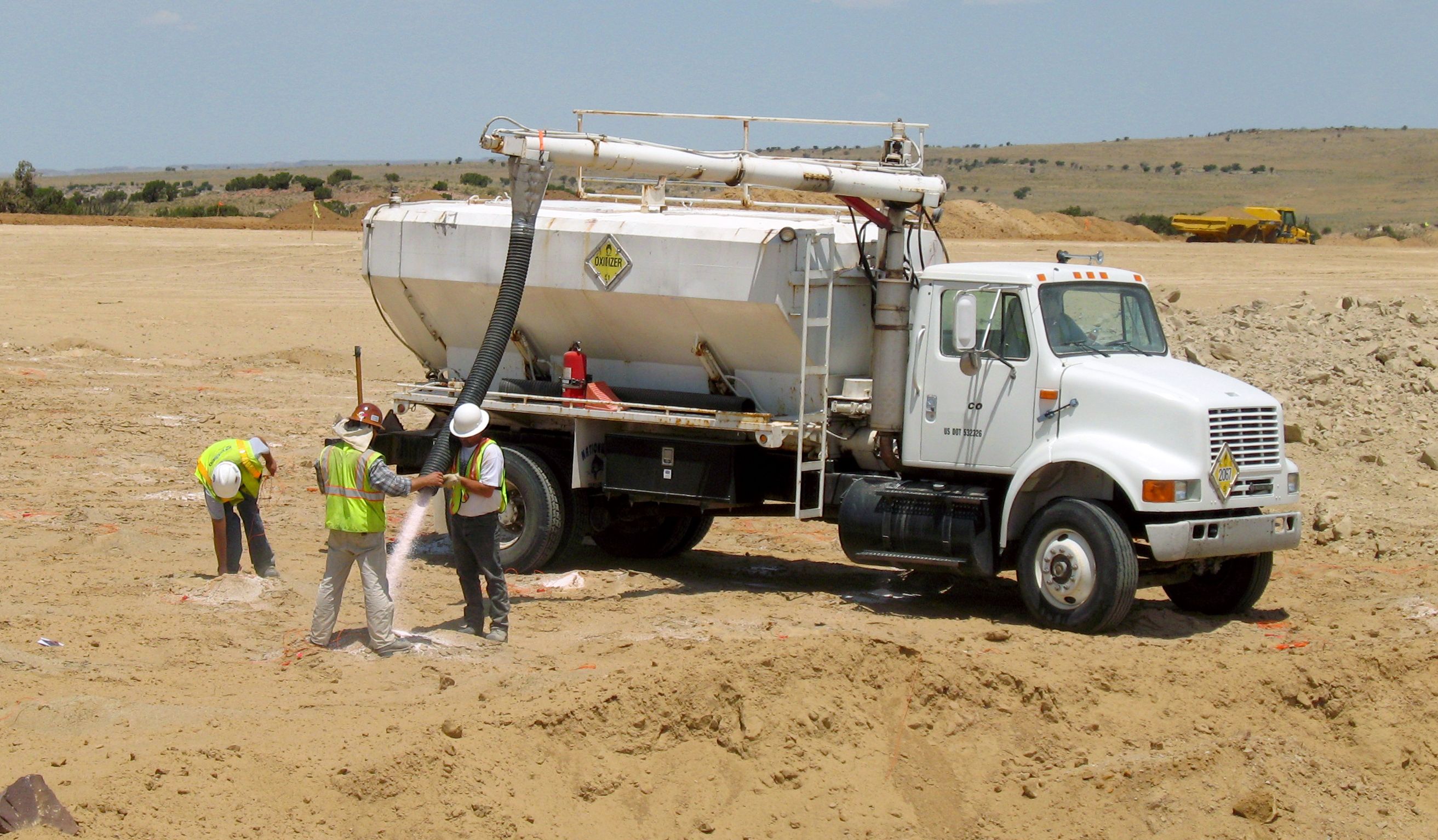
Once the drill holes are complete and inspected, charging the holes with explosives can begin. The type of blasting agents to be used is determined by the blasting plan, but in most cases, the agent of choice is ANFO, or ammonium nitrate and fuel oil. The ammonium nitrate, which contains 60% oxygen by weight, serves as an oxidizer for the combustion of the long-chain alkanes in the fuel oil. The ideal mix is 94% ammonium nitrate to 6% fuel oil.
Filling holes with ammonium nitrate at a blasting site. Hopper trucks like this are often used to carry prilled ammonium nitrate. Some trucks also have a tank for the fuel oil that’s added to the ammonium nitrate to make ANFO. Credit: Old Bear Photo, via Adobe Stock.
How the ANFO is added to the hole depends on conditions. For holes where groundwater is not a problem, ammonium nitrate in the form of small porous beads or prills, is poured down the hole and lightly tamped to remove any voids or air spaces before the correct amount of fuel oil is added. For wet conditions, an ammonium nitrate emulsion will be used instead. This is just a solution of ammonium nitrate in water with emulsifiers added to allow the fuel oil to mix with the oxidizer.
ANFO is classified as a tertiary explosive, meaning it is insensitive to shock and requires a booster to detonate. The booster charge is generally a secondary explosive such as PETN, or pentaerythritol tetranitrate, a powerful explosive that’s chemically similar to nitroglycerine but is much more stable. PETN comes in a number of forms, with cardboard cylinders like oversized fireworks or a PETN-laced gel stuffed into a plastic tube that looks like a sausage being the most common.
Electrically operated blasting caps marked with their built-in 425 ms delay. These will easily blow your hand clean off. Source: Timo Halén, CC BY-SA 2.5.
Being a secondary explosive, the booster charge needs a fairly strong shock to detonate. This shock is provided by a blasting cap or detonator, which is a small, multi-stage pyrotechnic device. These are generally in the form of a small brass or copper tube filled with a layer of primary explosive such as lead azide or fulminate of mercury, along with a small amount of secondary explosive such as PETN. The primary charge is in physical contact with an initiator of some sort, either a bridge wire in the case of electrically initiated detonators, or more commonly, a shock tube. Shock tubes are thin-walled plastic tubing with a layer of reactive explosive powder on the inner wall. The explosive powder is engineered to detonate down the tube at around 2,000 m/s, carrying a shock wave into the detonator at a known rate, which makes propagation delays easy to calculate.
Timing is critical to the blasting plan. If the explosives in each hole were to all detonate at the same time, there wouldn’t be anywhere for the displaced material to go. To prevent that, mining engineers build delays into the blasting plan so that some charges, typically the ones closest to the free face of the bench, go off a fraction of a second before the charges behind them, freeing up space for the displaced material to move into. Delays are either built into the initiator as a layer of pyrotechnic material that burns at a known rate between the initiator and the primary charge, or by using surface delays, which are devices with fixed delays that connect the initiator down the hole to the rest of the charges that will make up the shot. Lately, electronic detonators have been introduced, which have microcontrollers built in. These detonators are addressable and can have a specific delay programmed in the field, making it easier to program the delays needed for the entire shot. Electronic detonators also require a specific code to be transmitted to detonate, which reduces the chance of injury or misuse that lost or stolen electrical blasting caps present. This was enough of a problem that a series of public service films on the dangers of playing with blasting caps appeared regularly from the 1950s through the 1970s.
“Fire in the Hole!”
When all the holes are charged and properly stemmed, the blasting crew makes the final connections on the surface. Connections can be made with wires for electrical and electronic detonators, or with shock tubes for non-electric detonators. Sometimes, detonating cord is used to make the surface connections between holes. Det cord is similar to shock tube but generally looks like woven nylon cord. It also detonates at a much faster rate (6,500 m/s) than shock tube thanks to being filled with PETN or a similar high-velocity explosive.
Once the final connections to the blasting controller are made and tested, the area is secured with all personnel and equipment removed. A series of increasingly urgent warnings are sounded on sirens or horns as the blast approaches, to alert personnel to the danger. The blaster initiates the shot at the controller, which sends the signal down trunklines and into any surface delays before being transmitted to the detonators via their downlines. The relatively weak shock wave from the detonator propagates into the booster charge, which imparts enough energy into the ANFO to start detonation of the main charge.
The ANFO rapidly decomposes into a mixture of hot gases, including carbon dioxide, nitrogen, and water vapor. The shock wave pulverizes the rock surrounding the borehole and rapidly propagates into the surrounding rock, exerting tremendous compressive force. The shock wave continues to propagate until it meets a natural crack or the interface between rock and air at the free face of the shot. These impedance discontinuities reflect the compressive wave and turn it into a tensile wave, and since rock is generally much weaker in tension than compression, this is where the real destruction begins.
The reflected tensile forces break the rock along natural or newly formed cracks, creating voids that are filled with the rapidly expanding gases from the burning ANFO. The gases force these cracks apart, providing the heave needed to move rock fragments into the voids created by the initial shock wave. The shot progresses at the set delay intervals between holes, with the initial shock from new explosions creating more fractures deeper into the rock face and more expanding gas to move the fragments into the space created by earlier explosions. Depending on how many holes are in the shot and how long the delays are, the entire thing can be over in just a few seconds, or it could go on for quite some time, as it does in this world-record blast at a coal mine in Queensland in 2019, which used 3,899 boreholes packed with 2,194 tonnes of ANFO to move 4.7 million cubic meters of material in just 16 seconds.
There’s still much for the blasting crew to do once the shot is done. As the dust settles, safety crews use monitoring equipment to ensure any hazardous blasting gases have dispersed before sending in crews to look for any misfires. Misfires can result in a reshoot, where crews hook up a fresh initiator and try to detonate the booster charge again. If the charge won’t fire, it can be carefully extracted from the rubble pile with non-sparking tools and soaked in water to inactivate it.
Hold onto your hats, everyone — there’s stunning news afoot. It’s hard to believe, but it looks like over-reliance on chatbots to do your homework can turn your brain into pudding. At least that seems to be the conclusion of a preprint paper out of the MIT Media Lab, which looked at 54 adults between the ages of 18 and 39, who were tasked with writing a series of essays. They divided participants into three groups — one that used ChatGPT to help write the essays, one that was limited to using only Google search, and one that had to do everything the old-fashioned way. They recorded the brain activity of writers using EEG, in order to get an idea of brain engagement with the task. The brain-only group had the greatest engagement, which stayed consistently high throughout the series, while the ChatGPT group had the least. More alarmingly, the engagement for the chatbot group went down even further with each essay written. The ChatGPT group produced essays that were very similar between writers and were judged “soulless” by two English teachers. Go figure.
The most interesting finding, though, was when 18 participants from the chatbot and brain-only groups were asked to rewrite one of their earlier essays, with the added twist that the chatbot group had to do it all by themselves, while the brainiacs got to use ChatGPT. The EEGs showed that the first group struggled with the task, presumably because they failed to form any deep memory of their previous work thanks to over-reliance on ChatGPT. The brain-only folks, however, did well at the task and showed signs of activity across all EEG bands. That fits well with our experience with chatbots, which we use to help retrieve specific facts and figures while writing articles, especially ones we know we’ve seen during our initial scan of the literature but can’t find later.
Does anyone remember Elektro? We sure do, although not from personal experience, since the seven-foot-tall automaton built by Westinghouse for the World’s Fair in New York City in 1939 significantly predates our appearance on the planet. But still, the golden-skinned robot that made its living by walking around, smoking, and cracking wise at the audience thanks to a 78-rpm record player in its capacious chest, really made an impression, enough that it toured the country for the better part of 30 years and made the unforgettable Sex Kittens Go to College in 1960 before fading into obscurity. At some point, the one-of-a-kind robot was rescued from a scrap heap and restored to its former glory, and now resides in the North Central Ohio Industrial Museum in Mansfield, very close to the Westinghouse facility that built it. If you need an excuse to visit North Central Ohio, you could do worse than a visit to see Elektro.
It was with some alarm that we learned this week from Al Williams that mtrek.com 1701 appeared to be down. For those not in the know, mtrek is a Telnet space combat game inspired by the Star Trek franchise, which explains why Al was in such a tizzy about not being able to connect; huge Trek nerd, our Al. Anyway, it appears Al’s worst fears were unfounded, as we were able to connect to mtrek just fine. But in the process of doing so, we stumbled across this collection of Telnet games and demos that’s worth checking out. The mtrek, of course, as well as Telnet versions of chess and backgammon, and an interactive world map that always blows our mind. The site also lists the Telnet GOAT, the Star Wars Asciimation; sadly, that one does seem to be down, at least for us. Sure, you can see it in a web browser, but it’s not the same as watching it in a terminal over Telnet, is it?
And finally, if you’ve got 90 minutes or so to spare, you could do worse than to spend it with our friend Hash as he reverse engineers an automotive ECU. We have to admit that we haven’t indulged yet — it’s on our playlist for this weekend, because we know how to party. But from what Hash tells us, this is the tortured tale of a job that took far, far longer to complete than expected. We have to admit that while we’ll gladly undertake almost any mechanical repair on most vehicles, automotive ECUs and other electronic modules are almost a bridge too far for us, at least in terms of cracking them open to make even simple repairs. Getting access to them for firmware extraction and parameter fiddling sounds like a lot of fun, and we’re looking forward to hearing what Hash has to say about the subject.
For a world covered in oceans, getting a drink of water on Planet Earth can be surprisingly tricky. Fresh water is hard to come by even on our water world, so much so that most sources are better measured in parts per million than percentages; add together every freshwater lake, river, and stream in the world, and you’d be looking at a mere 0.0066% of all the water on Earth.
Of course, what that really says is that our endowment of saltwater is truly staggering. We have over 1.3 billion cubic kilometers of the stuff, most of it easily accessible to the billion or so people who live within 10 kilometers of a coastline. Untreated, though, saltwater isn’t of much direct use to humans, since we, our domestic animals, and pretty much all our crops thirst only for water a hundred times less saline than seawater.
While nature solved the problem of desalination a long time ago, the natural water cycle turns seawater into freshwater at too slow a pace or in the wrong locations for our needs. While there are simple methods for getting the salt out of seawater, such as distillation, processing seawater on a scale that can provide even a medium-sized city with a steady source of potable water is definitely a job for Big Chemistry.
Biology Backwards
Understanding an industrial chemistry process often starts with a look at the feedstock, so what exactly is seawater? It seems pretty obvious, but seawater is actually a fairly complex solution that varies widely in composition. Seawater averages about 3.5% salinity, which means there are 35 grams of dissolved salts in every liter. The primary salt is sodium chloride, with potassium, magnesium, and calcium salts each making a tiny contribution to the overall salinity. But for purposes of acting as a feedstock for desalination, seawater can be considered a simple sodium chloride solution where sodium anions and chloride cations are almost completely dissociated. The goal of desalination is to remove those ions, leaving nothing but water behind.
While thermal desalination methods, such as distillation, are possible, they tend not to scale well to industrial levels. Thermal methods have their place, though, especially for shipboard potable water production and in cases where fuel is abundant or solar energy can be employed to heat the seawater directly. However, in most cases, industrial desalination is typically accomplished through reverse osmosis RO, which is the focus of this discussion.
In biological systems, osmosis is the process by which cells maintain equilibrium in terms of concentration of solutes relative to the environment. The classic example is red blood cells, which if placed in distilled water will quickly burst. That’s because water from the environment, which has a low concentration of solutes, rushes across the semi-permeable cell membrane in an attempt to dilute the solutes inside the cell. All that water rushing into the cell swells it until the membrane can’t take the pressure, resulting in hemolysis. Conversely, a blood cell dropped into a concentrated salt solution will shrink and wrinkle, or crenellate, as the water inside rushes out to dilute the outside environment.
Water rushes in, water rushes out. Either way, osmosis is bad news for red blood cells. Reversing the natural osmotic flow of a solution like seawater is the key to desalination by reverse osmosis. Source: Emekadecatalyst, CC BY-SA 4.0.
Reverse osmosis is the opposite process. Rather than water naturally following a concentration gradient to equilibrium, reverse osmosis applies energy in the form of pressure to force the water molecules in a saline solution through a semipermeable membrane, leaving behind as many of the salts as possible. What exactly happens at the membrane to sort out the salt from the water is really the story, and as it turns out, we’re still not completely clear how reverse osmosis works, even though we’ve been using it to process seawater since the 1950s.
Battling Models
Up until the early 2020s, the predominant model for how reverse osmosis (RO) worked was called the “solution-diffusion” model. The SD model treated RO membranes as effectively solid barriers through which water molecules could only pass by first diffusing into the membrane from the side with the higher solute concentration. Once inside the membrane, water molecules would continue through to the other side, the permeate side, driven by a concentration gradient within the membrane. This model had several problems, but the math worked well enough to allow the construction of large-scale seawater RO plants.
The new model is called the “solution-friction” model, and it better describes what’s going on inside the membrane. Rather than seeing the membrane as a solid barrier, the SF model considers the concentrate and permeate surfaces of the membrane to communicate through a series of interconnected pores. Water is driven across the membrane not by concentration but by a pressure gradient, which drives clusters of water molecules through the pores. The friction of these clusters against the walls of the pores results in a linear pressure drop across the membrane, an effect that can be measured in the lab and for which the older SD model has no explanation.
As for the solutes in a saline solution, the SF model accounts for their exclusion from the permeate by a combination of steric hindrance (the solutes just can’t fit through the pores), the Donnan effect (which says that ions with the opposite charge of the membrane will get stuck inside it), and dielectric exclusion (the membrane presents an energy barrier that makes it hard for ions to enter it). The net result of these effects is that ions tend to get left on one side of the membrane, while water molecules can squeeze through more easily to the permeate side.
Turning these models into a practical industrial process takes a great deal of engineering. A seawater reverse osmosis or SWRO, plant obviously needs to be located close to the shore, but also needs to be close to supporting infrastructure such as a municipal water system to accept the finished product. SWRO plants also use a lot of energy, so ready access to the electrical grid is a must, as is access to shipping for the chemicals needed for pre- and post-treatment.
Pores and Pressure
Seawater processing starts with water intake. Some SWRO plants use open intakes located some distance out from the shoreline, well below the lowest possible tides and far from any potential source of contamination or damage, such a ship anchorages. Open intakes generally have grates over them to exclude large marine life and debris from entering the system. Other SWRO plants use beach well intakes, with shafts dug into the beach that extend below the water table. Seawater filters through the sand and fills the well; from there, the water is pumped into the plant. Beach wells have the advantage of using the beach sand as a natural filter for particulates and smaller sea critters, but do tend to have a lower capacity than open intakes.
Aside from the salts, seawater has plenty of other unwanted bits, all of which need to come out prior to reverse osmosis. Trash racks remove any shells, sea life, or litter that manage to get through the intakes, and sand bed filters are often used to remove smaller particulates. Ultrafiltration can be used to further clarify the seawater, and chemicals such as mild acids or bases are often used to dissolve inorganic scale and biofilms. Surfactants are often added to the feedstock, too, to break up heavy organic materials.
By the time pretreatment is complete, the seawater is remarkably free from suspended particulates and silt. Pretreatment aims to reduce the turbidity of the feedstock to less than 0.5 NTUs, or nephelometric turbidity units. For context, the US Environmental Protection Agency standard for drinking water is 0.3 NTUs for 95% of the samples taken in a month. So the pretreated seawater is almost as clear as drinking water before it goes to reverse osmosis.
SWRO cartridges have membranes wound into spirals and housed in pressure vessels. Seawater under high pressure enters the membrane spiral; water molecules migrate across the membrane to a center permeate tube, leaving a reject brine that’s about twice as saline as the feedstock. Source: DuPont Water Solutions.
The heart of reverse osmosis is the membrane, and a lot of engineering goes into it. Modern RO membranes are triple-layer thin-film composites that start with a non-woven polyester support, a felt-like material that provides the mechanical strength to withstand the extreme pressures of reverse osmosis. Next comes a porous support layer, a 50 μm-thick layer of polysulfone cast directly onto the backing layer. This layer adds to the physical strength of the backing and provides a strong yet porous foundation for the active layer, a cross-linked polyamide layer about 100 to 200 nm thick. This layer is formed by interfacial polymerization, where a thin layer of liquid monomer and initiators is poured onto the polysulfone to polymerize in place.
An RO rack in a modern SWRO desalination plant. Each of the white tubes is a pressure vessel containing seven or eight RO membrane cartridges. The vessels are plumbed in parallel to increase flow through the system. Credit: Elvis Santana, via Adobe Stock.
Modern membranes can flow about 35 liters per square meter every hour, which means an SWRO plant needs to cram a lot of surface area into a little space. This is accomplished by rolling the membrane up into a spiral and inserting it into a fiberglass pressure vessel, which holds seven or eight cartridges. Seawater pumped into the vessel soaks into the backing layer to the active layer, where only the water molecules pass through and into a collection pipe at the center of the roll. The desalinated water, or permeate, exits the cartridge through the center pipe while rejected brine exits at the other end of the pressure vessel.
The pressure needed for SWRO is enormous. The natural osmotic pressure of seawater is about 27 bar (27,000 kPa), which is the pressure needed to halt the natural flow of water across a semipermeable membrane. SWRO systems must pressurize the water to at least that much plus a net driving pressure (NPD) to overcome mechanical resistance to flow through the membrane, which amounts to an additional 30 to 40 bar.
Energy Recovery
To achieve these tremendous pressures, SWRO plants use multistage centrifugal pumps driven by large, powerful electric motors, often 300 horsepower or more for large systems. The electricity needed to run those motors accounts for 60 to 80 percent of the energy costs of the typical SWRO plant, so a lot of effort is put into recovering that energy, most of which is still locked up in the high-pressure rejected brine as hydraulic energy. This energy used to be extracted by Pelton-style turbines connected to the shaft of the main pressure pump; the high-pressure brine would spin the pump shaft and reduce the mechanical load on the pump, which would reduce the electrical load. Later, the brine’s energy would be recovered by a separate turbo pump, which would boost the pressure of the feed water before it entered the main pump.
While both of these methods were capable of recovering a large percentage of the input energy, they were mechanically complex. Modern SWRO plants have mostly moved to isobaric energy recovery devices, which are mechanically simpler and require much less maintenance. Isobaric ERDs have a single moving part, a cylindrical ceramic rotor. The rotor has a series of axial holes, a little like the cylinder of an old six-shooter revolver. The rotor is inside a cylindrical housing with endcaps on each end, each with an inlet and an outlet fitting. High-pressure reject brine enters the ERD on one side while low-pressure seawater enters on the other side. The slugs of water fill the same bore in the rotor and equalize at the same pressure without much mixing thanks to the different densities of the fluids. The rotor rotates thanks to the momentum carried by the incoming water streams and inlet fittings that are slightly angled relative to the axis of the bore. When the rotor lines up with the outlet fittings in each end cap, the feed water and the brine both exit the rotor, with the feed water at a higher pressure thanks to the energy of the reject brine.
For something with only one moving part, isobaric ERDs are remarkably effective. They can extract about 98% of the energy in the reject brine, pressuring the feed water about 60% of the total needed. An SWRO plant with ERDs typically uses 5 to 6 kWh to produce a cubic meter of desalinated water; ERDs can slash that to just 2 to 3 kWh.
Isobaric energy recovery devices can recover half of the electricity used by the typical SWRO plant by using the pressure of the reject brine to pressurize the feed water. Source: Flowserve.
Finishing Up
Once the rejected brine’s energy has been recovered, it needs to be disposed of properly. This is generally done by pumping it back out into the ocean through a pipe buried in the seafloor. The outlet is located a considerable distance from the inlet and away from any ecologically sensitive areas. The brine outlet is also generally fitted with a venturi induction head, which entrains seawater from around the outlet to partially dilute the brine.
As for the permeate that comes off the RO racks, while it is almost completely desalinated and very clean, it’s still not suitable for distribution into the drinking water system. Water this clean is highly corrosive to plumbing fixtures and has an unpleasantly flat taste. To correct this, RO water is post-processed by passing it over beds of limestone chips. The RO water tends to be slightly acidic thanks to dissolved CO2, so it partially dissolves the calcium carbonate in the limestone. This raises the pH closer to neutral and adds calcium ions to the water, which increases its hardness a bit. The water also gets a final disinfection with chlorine before being released to the distribution network.
Are robotaxis poised to be the Next Big Thing in North America? It seems so, at least according to Goldman Sachs, which issued a report this week stating that robotaxis have officially entered the commercialization phase of the hype cycle. That assessment appears to be based on an analysis of the total ride-sharing market, which encompasses services that are currently almost 100% reliant on meat-based drivers, such as Lyft and Uber, and is valued at $58 billion. Autonomous ride-hailing services like Waymo, which has a fleet of 1,500 robotaxis operating in several cities across the US, are included in that market but account for less than 1% of the total right now. But, Goldman projects that the market will burgeon to over $336 billion in the next five years, driven in large part by “hyperscaling” of autonomous vehicles.
We suspect the upcoming launch of Tesla’s robotaxis in Austin, Texas, accounts for some of this enthusiasm for the near-term, but we have our doubts that a market based on such new and complex technologies can scale that quickly. A little back-of-the-envelope math suggests that the robotaxi fleet will need to grow to about 9,000 cars in the next five years, assuming the same proportion of autonomous cars in the total ride-sharing fleet as exists today. A look inside the Waymo robotaxi plant outside of Phoenix reveals that it can currently only convert “several” Jaguar electric SUVs per day, meaning they’ve got a lot of work to do to meet the needed numbers. Other manufacturers will no doubt pitch in, especially Tesla, and factory automation always seems to pull off miracles under difficult circumstances, but it still seems like a stretch to think there’ll be that many robotaxis on the road in only five years. Also, it currently costs more to hail a robotaxi than an Uber or Lyft, and we just don’t see why anyone would prefer to call a robotaxi, unless it’s for the novelty of the experience.
On the other hand, if the autonomous ride-sharing market does experience explosive growth, there could be knock-on benefits even for Luddite naysayers such as we. A report, again from Goldman Sachs — hey, they probably have a lot of skin in the game — predicts that auto insurance rates could fall by 50% as more autonomous cars hit the streets. This is based on markedly lower liability for self-driving cars, which have 92% fewer bodily injury claims and 88% lower property damage claims than human-driven cars. Granted, those numbers have to be based on a very limited population, and we guarantee that self-drivers will find new and interesting ways to screw up on the road. But if our insurance rates fall even a little because of self-driving cars, we’ll take it as a win.
Speaking of robotics, if you want to see just how far we’ve come in terms of robot dexterity, look no further than the package-sorting abilities of Figure’s Helix robot. The video in the article is an hour long, but you don’t need to watch more than a few minutes to be thoroughly impressed. The robot is standing at a sorting table with an infeed conveyor loaded with just about the worst parcels possible, a mix of soft, floppy, poly-bagged packages, flat envelopes, and traditional boxes. The robot was tasked with placing the parcels on an outfeed conveyor, barcode-side down, and with proper separation between packages. It also treats the soft poly-bag parcels to a bit of extra attention, pressing them down a bit to flatten them before flicking them onto the belt. Actually, it’s that flicking action that seems the most human, since it’s accompanied by a head-swivel to the infeed belt to select its next package. Assuming this is legit autonomous and not covertly teleoperated, which we have no reason to believe, the manual dexterity on display here is next-level; we’re especially charmed by the carefree little package flip about a minute in. The way it handles mistakenly grabbing two packages at once is pretty amazing, too.
And finally, our friend Leo Fernekes dropped a new video that’ll hit close to home for a lot of you out there. Leo is a bit of a techno-hoarder, you see, and with the need to make some room at home and maintain his domestic tranquility, he had to tackle the difficult process of getting rid of old projects, some of which date back 40 or more years. Aside from the fun look through his back-catalog of projects, the video is also an examination of the emotional attachments we hackers tend to develop to our projects. We touched on that a bit in our article on tech anthropomorphization, but we see how going through these projects is not only a snapshot of the state of the technology available at the time, but also a slice of life. Each of the projects is not just a collection of parts, they’re collections of memories of where Leo was in life at the time. Sometimes it’s hard to let go of things that are so strongly symbolic of a time that’s never coming back, and we applaud Leo for having the strength to pitch that stuff. Although seeing a clock filled with 80s TTL chips and a vintage 8085 microprocessor go into the bin was a little tough to watch.
What happens when you build the largest machine in the world, but it’s still not big enough? That’s the situation the North American transmission system, the grid that connects power plants to substations and the distribution system, and which by some measures is the largest machine ever constructed, finds itself in right now. After more than a century of build-out, the towers and wires that stitch together a continent-sized grid aren’t up to the task they were designed for, and that’s a huge problem for a society with a seemingly insatiable need for more electricity.
There are plenty of reasons for this burgeoning demand, including the rapid growth of data centers to support AI and other cloud services and the move to wind and solar energy as the push to decarbonize the grid proceeds. The former introduces massive new loads to the grid with millions of hungry little GPUs, while the latter increases the supply side, as wind and solar plants are often located out of reach of existing transmission lines. Add in the anticipated expansion of the manufacturing base as industry seeks to re-home factories, and the scale of the potential problem only grows.
The bottom line to all this is that the grid needs to grow to support all this growth, and while there is often no other solution than building new transmission lines, that’s not always feasible. Even when it is, the process can take decades. What’s needed is a quick win, a way to increase the capacity of the existing infrastructure without having to build new lines from the ground up. That’s exactly what reconductoring promises, and the way it gets there presents some interesting engineering challenges and opportunities.
Bare Metal
Copper is probably the first material that comes to mind when thinking about electrical conductors. Copper is the best conductor of electricity after silver, it’s commonly available and relatively easy to extract, and it has all the physical characteristics, such as ductility and tensile strength, that make it easy to form into wire. Copper has become the go-to material for wiring residential and commercial structures, and even in industrial installations, copper wiring is a mainstay.
However, despite its advantages behind the meter, copper is rarely, if ever, used for overhead wiring in transmission and distribution systems. Instead, aluminum is favored for these systems, mainly due to its lower cost compared to the equivalent copper conductor. There’s also the factor of weight; copper is much denser than aluminum, so a transmission system built on copper wires would have to use much sturdier towers and poles to loft the wires. Copper is also much more subject to corrosion than aluminum, an important consideration for wires that will be exposed to the elements for decades.
ACSR (left) has a seven-strand steel core surrounded by 26 aluminum conductors in two layers. ACCC has three layers of trapezoidal wire wrapped around a composite carbon fiber core. Note the vastly denser packing ratio in the ACCC. Source: Dave Bryant, CC BY-SA 3.0.
Aluminum has its downsides, of course. Pure aluminum is only about 61% as conductive as copper, meaning that conductors need to have a larger circular area to carry the same amount of current as a copper cable. Aluminum also has only about half the tensile strength of copper, which would seem to be a problem for wires strung between poles or towers under a lot of tension. However, the greater diameter of aluminum conductors tends to make up for that lack of strength, as does the fact that most aluminum conductors in the transmission system are of composite construction.
The vast majority of the wires in the North American transmission system are composites of aluminum and steel known as ACSR, or aluminum conductor steel-reinforced. ACSR is made by wrapping high-purity aluminum wires around a core of galvanized steel wires. The core can be a single steel wire, but more commonly it’s made from seven strands, six wrapped around a single central wire; especially large ACSR might have a 19-wire core. The core wires are classified by their tensile strength and the thickness of their zinc coating, which determines how corrosion-resistant the core will be.
In standard ACSR, both the steel core and the aluminum outer strands are round in cross-section. Each layer of the cable is twisted in the opposite direction from the previous layer. Alternating the twist of each layer ensures that the finished cable doesn’t have a tendency to coil and kink during installation. In North America, all ACSR is constructed so that the outside layer has a right-hand lay.
ACSR is manufactured by machines called spinning or stranding machines, which have large cylindrical bodies that can carry up to 36 spools of aluminum wire. The wires are fed from the spools into circular spinning plates that collate the wires and spin them around the steel core fed through the center of the machine. The output of one spinning frame can be spooled up as finished ACSR or, if more layers are needed, can pass directly into another spinning frame for another layer of aluminum, in the opposite direction, of course.
Fiber to the Core
While ACSR is the backbone of the grid, it’s not the only show in town. There’s an entire beastiary of initialisms based on the materials and methods used to build composite cables. ACSS, or aluminum conductor steel-supported, is similar to ACSR but uses more steel in the core and is completely supported by the steel, as opposed to ACSR where the load is split between the steel and the aluminum. AAAC, or all-aluminum alloy conductor, has no steel in it at all, instead relying on high-strength aluminum alloys for the necessary tensile strength. AAAC has the advantage of being very lightweight as well as being much more resistant to core corrosion than ACSR.
Another approach to reducing core corrosion for aluminum-clad conductors is to switch to composite cores. These are known by various trade names, such as ACCC (aluminum conductor composite core) or ACCR (aluminum conductor composite reinforced). In general, these cables are known as HTLS, which stands for high-temperature, low-sag. They deliver on these twin promises by replacing the traditional steel core with a composite material such as carbon fiber, or in the case of ACCR, a fiber-reinforced metal matrix.
The point of composite cores is to provide the conductor with the necessary tensile strength and lower thermal expansion coefficient, so that heating due to loading and environmental conditions causes the cable to sag less. Controlling sag is critical to cable capacity; the less likely a cable is to sag when heated, the more load it can carry. Additionally, composite cores can have a smaller cross-sectional area than a steel core with the same tensile strength, leaving room for more aluminum in the outer layers while maintaining the same overall conductor diameter. And of course, more aluminum means these advanced conductors can carry more current.
Another way to increase the capacity in advanced conductors is by switching to trapezoidal wires. Traditional ACSR with round wires in the core and conductor layers has a significant amount of dielectric space trapped within the conductor, which contributes nothing to the cable’s current-carrying capacity. Filling those internal voids with aluminum is accomplished by wrapping round composite cores with aluminum wires that have a trapezoidal cross-section to pack tightly against each other. This greatly reduces the dielectric space trapped within a conductor, increasing its ampacity within the same overall diameter.
Unfortunately, trapezoidal aluminum conductors are much harder to manufacture than traditional round wires. While creating the trapezoids isn’t that much harder than drawing round aluminum wire — it really just requires switching to a different die — dealing with non-round wire is more of a challenge. Care must be taken not to twist the wire while it’s being rolled onto its spools, as well as when wrapping the wire onto the core. Also, the different layers of aluminum in the cable require different trapezoidal shapes, lest dielectric voids be introduced. The twist of the different layers of aluminum has to be controlled, too, just as with round wires. Trapezoidal wires can also complicate things for linemen in the field in terms of splicing and terminating cables, although most utilities and cable construction companies have invested in specialized tooling for advanced conductors.
Same Towers, Better Wires
The grid is what it is today in large part because of decisions made a hundred or more years ago, many of which had little to do with engineering. Power plants were located where it made sense to build them relative to the cities and towns they would serve and the availability of the fuel that would power them, while the transmission lines that move bulk power were built where it was possible to obtain rights-of-way. These decisions shaped the physical footprint of the grid, and except in cases where enough forethought was employed to secure rights-of-way generous enough to allow for expansion of the physical plant, that footprint is pretty much what engineers have to work with today.
Increasing the amount of power that can be moved within that limited footprint is what reconductoring is all about. Generally, reconductoring is pretty much what it sounds like: replacing the conductors on existing support structures with advanced conductors. There are certainly cases where reconductoring alone won’t do, such as when new solar or wind plants are built without existing transmission lines to connect them to the system. In those cases, little can be done except to build a new transmission line. And even where reconductoring can be done, it’s not cheap; it can cost 20% more per mile than building new towers on new rights-of-way. But reconductoring is much, much faster than building new lines. A typical reconductoring project can be completed in 18 to 36 months, as compared to the 5 to 15 years needed to build a new line, thanks to all the regulatory and legal challenges involved in obtaining the property to build the structures on. Reconductoring usually faces fewer of these challenges, since rights-of-way on existing lines were established long ago.
The exact methods of reconductoring depend on the specifics of the transmission line, but in general, reconductoring starts with a thorough engineering evaluation of the support structures. Since most advanced conductors are the same weight per unit length as the ACSR they’ll be replacing, loads on the towers should be about the same. But it’s prudent to make sure, and a field inspection of the towers on the line is needed to make sure they’re up to snuff. A careful analysis of the design capacity of the new line is also performed before the project goes through the permitting process. Reconductoring is generally performed on de-energized lines, which means loads have to be temporarily shifted to other lines, requiring careful coordination between utilities and transmission operators.
Once the preliminaries are in place, work begins. Despite how it may appear, most transmission lines are not one long cable per phase that spans dozens of towers across the countryside. Rather, most lines span just a few towers before dead-ending into insulators that use jumpers to carry current across to the next span of cable. This makes reconductoring largely a tower-by-tower affair, which somewhat simplifies the process, especially in terms of maintaining the tension on the towers while the conductors are swapped. Portable tensioning machines are used for that job, as well as for setting the proper tension in the new cable, which determines the sag for that span.
The tooling and methods used to connect advanced conductors to fixtures like midline splices or dead-end adapters are similar to those used for traditional ACSR construction, with allowances made for the switch to composite cores from steel. Hydraulic crimping tools do most of the work of forming a solid mechanical connection between the fixture and the core, and then to the outer aluminum conductors. A collet is also inserted over the core before it’s crimped, to provide additional mechanical strength against pullout.
Is all this extra work to manufacture and deploy advanced conductors worth it? In most cases, the answer is a resounding “Yes.” Advanced conductors can often carry twice the current as traditional ACSR or ACCC conductors of the same diameter. To take things even further, advanced AECC, or aluminum-encapsulated carbon core conductors, which use pretensioned carbon fiber cores covered by trapezoidal annealed aluminum conductors, can often triple the ampacity of equivalent-diameter ACSR.
Doubling or trebling the capacity of a line without the need to obtain new rights-of-way or build new structures is a huge win, even when the additional expense is factored in. And given that an estimated 98% of the existing transmission lines in North America are candidates for reconductoring, you can expect to see a lot of activity under your local power lines in the years to come.