Vehicles that change their shape and form to adapt to their operating environment have long captured the imagination of tech enthusiasts, and building one remains a perennial project dream for many makers. Now, [Michael Rechtin] has made the dream a bit more accessible with a 3D printed quadcopter that seamlessly transforms into a tracked ground vehicle.
The design tackles a critical engineering challenge: most multi-mode vehicles struggle with the vastly different rotational speeds required for flying and driving. [Michael]’s solution involves using printed prop guards as wheels, paired with lightweight tracks. An extra pair of low-speed brushless motors are mounted between each wheel pair, driving the system via sprockets that engage directly with the same teeth that drive the tracks.
The transition magic happens through a four-bar linkage mounted in a parallelogram configuration, with a linear actuator serving as the bottom bar. To change from flying to driving configuration the linear actuator retracts, rotating the wheels/prop guards to a vertical position. A servo then rotates the top bar, lifting the body off the ground. While this approach adds some weight — an inevitable compromise in multi-purpose machines — it makes for a practical solution.
Powering this transformer is a Teensy 4.0 flight controller running dRehmFlight, a hackable flight stabilization package we’ve seen successfully adapted for everything from VTOLs to actively stabilized hydrofoils.
Battling weeds can be expensive, labor intensive and use large amounts of chemicals. To help make this easier [NathanBuilds] has developed V2 of his open-source drone weed spraying system, complete with automated battery swaps, herbicide refills, and an AI vision system for weed identification.
The drone has a 3D printed frame, doubling as a chemical reservoir. V1 used a off-the-shelf frame, with separate tank. Surprisingly, it doesn’t look like [Nathan] had issues with leaks between the layer lines. For autonomous missions, it uses ArduPilot running on a PixHawk, coupled with RTK GPS for cm-level accuracy and a LiDAR altimeter. [Nathan] demonstrated the system in a field where he is trying to eradicate invasive blackberry bushes while minimizing the effect on the native prairie grass. He uses a custom image classification model running on a Raspberry Pi Zero, which only switches on the sprayers when it sees blackberry bushes in the frame. The Raspberry Pi Global Shutter camera is used to get blur-free images.
At just 305×305 mm (1×1 ft), the drone has limited herbicide capacity, and we expect the flights to be fairly short. For the automated pit stops, the drone lands on a 6×8 ft pad, where a motorized capture system pulls the drone into the reload bay. Here a linear actuator pushes a new battery into the side of the drone while pushing the spend battery one out the other side. The battery unit is a normal LiPo battery in 3D-printed frame. The terminal are connected to copper wire and tape contacts on the outside the battery unit, which connect to matching contacts in the drone and charging receptacles. This means the battery can easily short if it touches a metal surface, but a minor redesign could solve this quickly. There are revolving receptacles on either side of the reload bay, which immediately start charging the battery when ejected from the drone.
Developing a fully integrated system like this is no small task, and it shows a lot of potential. It might look a little rough around the edges, but [Nathan] has released all the design files and detailed video tutorials for all the subsystems, so it’s ready for refinement.
Besides Pokémon, there might have been no greater media franchise for a child of the 90s than the Transformers, mysterious robots fighting an intergalactic war but which can inexplicably change into various Earth-based object, like trucks and airplanes. It led to a number of toys which can also change shapes from fighting robots into various ordinary objects as well. And, perhaps in a way of life imitating art, plenty of real-life robots have features one might think were inspired by this franchise like this transforming quadruped robot.
Called the CYOBot, the robot has four articulating arms with a wheel at the end of each. The arms can be placed in a wide array of positions for different operating characteristics, allowing the robot to move in an incredibly diverse way. It’s based on a previous version called the CYOCrawler, using similar articulating arms but with no wheels. The build centers around an ESP32-S3 microcontroller, giving it plenty of compute power for things like machine learning, as well as wireless capabilities for control or access to more computing power.
Both robots are open source and modular as well, allowing a range of people to use and add on to the platform. Another perk here is that most parts are common or 3d printed, making it a fairly low barrier to entry for a platform with so many different configurations and options for expansion and development. If you prefer robots without wheels, though, we’d always recommend looking at Strandbeests for inspiration.
Even in the advanced world of 2024, robots are still better in science fiction than in reality. Star Trek gave us the erudite and refined Data, Rogue One gave us the fierce yet funny K-2SO, and Big Hero 6 gave us the caring charmer named Baymax. All these robots had smarts, capability, and agency. More than that, though—they were faithful(ish) companions to humans, fulfilling what that role entails.
The thing is, we’re not gonna get robots like that unless somebody builds them. [Angela Sheehan] is a artist and an educator, and a maker—and she’s trying to create exactly that. She came down to the 2023 Hackaday Supercon to tell us all about her efforts to create cuddly companion bots for real.
Beep Boop
You might remember Angela from her 2019 Supercon costume—she showed up dressed as a color-changing fairy. In fact, she has dabbled in all kinds of fields, which has given her a broad skillset applicable to creating companion bots. She’s done lots of costuming and cosplay over the years, she’s worked in product design, and she brands herself a bit of a fashion hacker. These skills might not be particularly relevant to building a high-speed industrial robot arm to perform 2000 welds an hour. However, they come in absolute clutch when you’re trying to build a robot that acts as a soft, cuddly companion. She notes that she was inspired to create her own companion bots by the work of others formerly showcased by Hackaday—you might remember work in this field from Alex Glow and Jorvon Moss.
That’s Nova, right there!
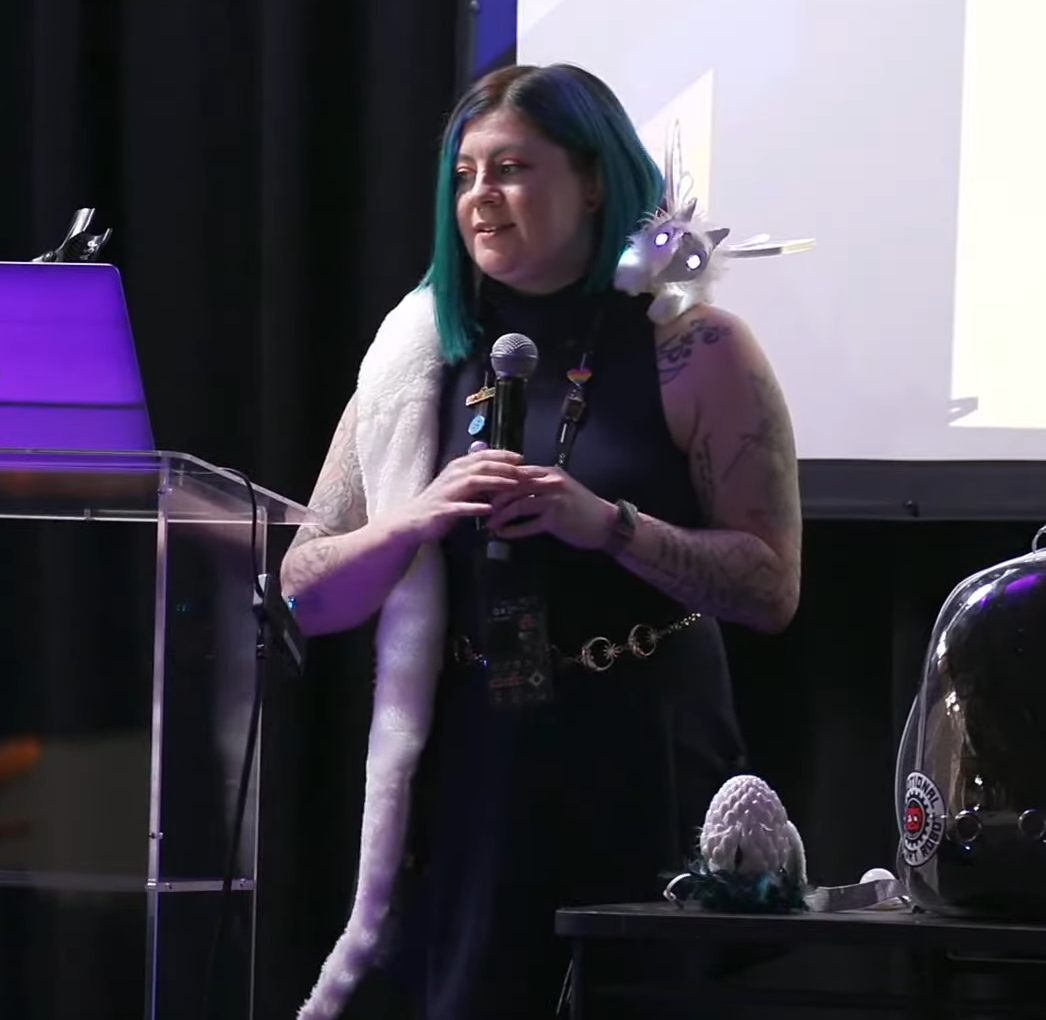
Angela’s talk soon tackles the elephant in the room—from the drop, you’ve probably been wondering about the cute critter perched on her shoulder. The long-tailed creature is named Nova, and she’s remarkably friendly and soothing once you get to know her.
Development took some time, with Angela doing lots of research and development to create the Nova we see today. “I actually did a lot of the prototyping and field testing for this bot in the library makerspace that I work at,” she explains. “It was great to see people who don’t know the inside and out of technology interact with [Nova] and I could pinpoint the moment that she became alive to people.” The bot got quite a response, transcending the level of basic machine to something a little more. “People wanted to come in and visit her and pet her,” says Angela. “That was such a powerful moment… that happened as soon as I started putting a face on her.” Angela doesn’t just tell the tale—during the talk, she passes Nova to the audience so they can interact with her up close. She explains that this is something that she does regularly—and we get to see photos of the lovely interactions Nova has had with dozens of smiling, happy people.
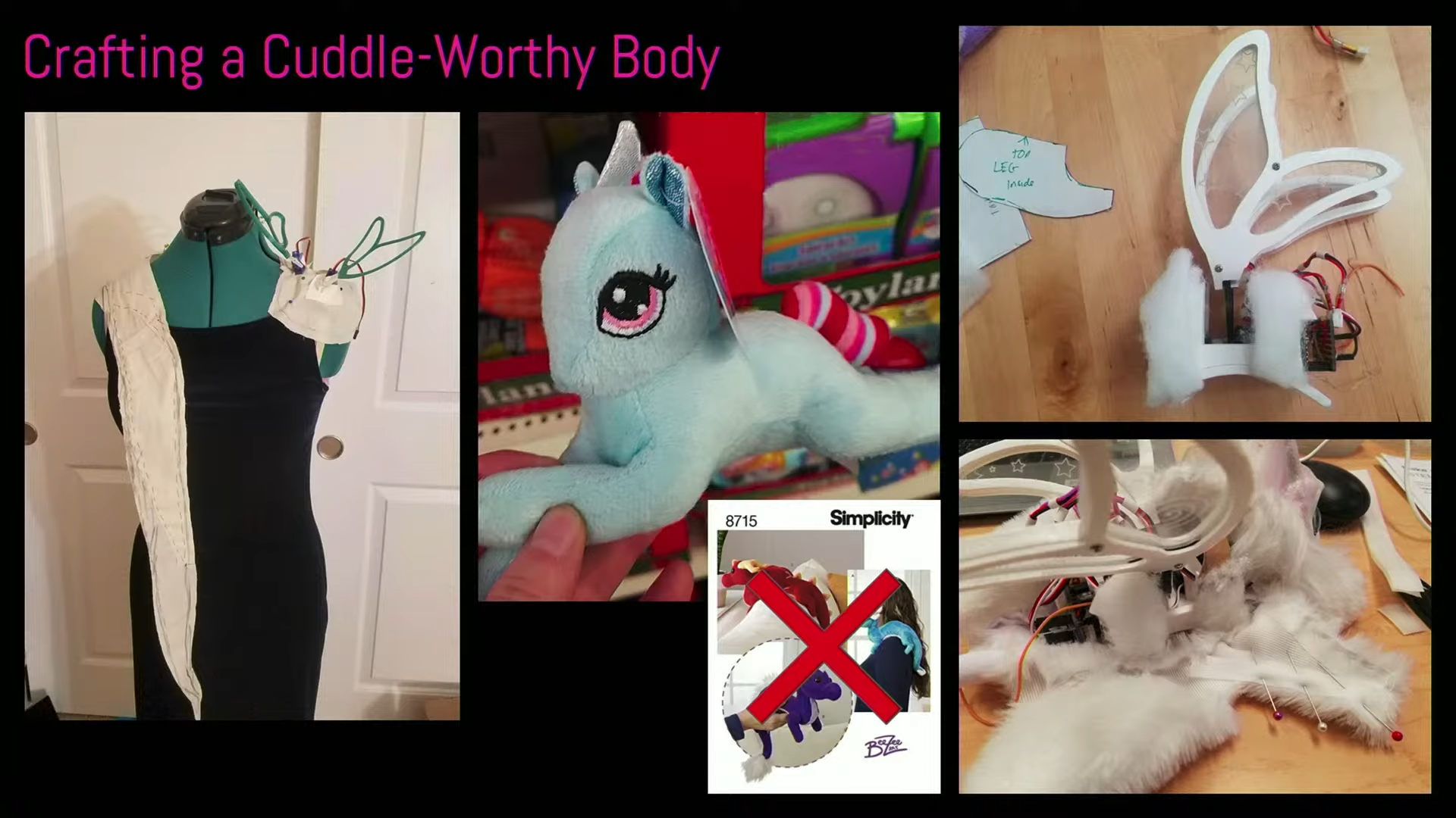
[Angela] covers some of the tools and techniques she used to develop her robot companion. At times, she looked to commercial products to figure out how to make something that’s properly cuddleable.Nova leverages Angela’s skills in sewing, 3D modelling, and 3D printing. She explains how components like Nova’s wings were first drafted in Adobe Illustrator. From there, the structure was refined into actual models in Fusion 360, while a PCB was developed in Eagle for the lighting electronics.
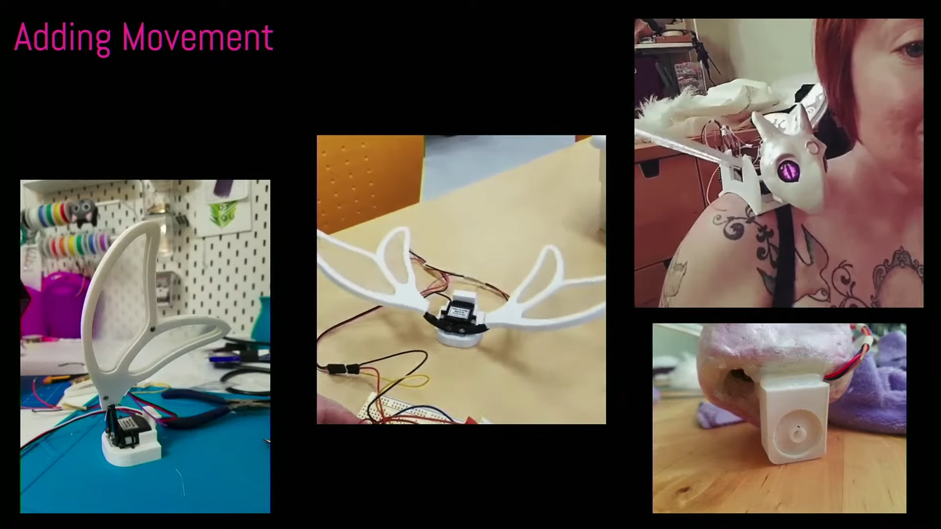
The face, though, was perhaps most crucial—as is the case for any anthropomorphic character. She took inspiration from Toothless from How To Train Your Dragon, using a stuffed toy as reference. Initial attempts weren’t particularly satisfying though, so she learned 3D sculpting for a further attempt in clay. Feedback from Twitter helped her develop the face further into the Nova we see today. The eyes were sourced from an Etsy supplier specializing in doll eyes. Angela notes there’s some magic there—when backlit with LEDs, switching them on and off can create a really believable blink pattern that feels super realistic. “What are those elements that make it feel alive?” Angela muses. “There are just little pieces of the psychology of it that you can dial into and you can make something that feels very alive.”
Part of the development process was figuring out how to make the eyes and movements feel natural—like a living creature rather than a pile of electronics, motors, and lights.
The talk then covers the rest of the design that helps create the “illusion of life.” Angela explains using servos and a robot gripper mechanism to flap the wings, and dialing in the motion so it felt as authentic as possible. She also covers robustness, designing “cuddle-worthy” bodies, and the value of designing for modularity. There’s also a useful discussion about how to make these builds more accessible, including useful starting points like which microcontroller and code platforms are good to use.
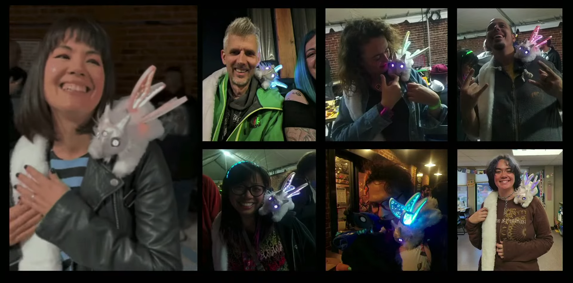
Even better, we get a look into the companion bot community, and we learn about the emotional impact these robots can have. Sometimes that’s intentional, other times, it’s down to a happy accident. “There is an unintended effect with [Nova’s] servos, that it feels like a purr,” says Angela. “It’s very comforting right on your shoulder, and I was thinking maybe I should try and insulate it a little bit, but actually people love it.”
Nova puts smiles on faces wherever she goes. Angela is always letting people hold her and get to know her, and this kind of gleeful response is a common one.
Fundamentally, companion bots are a bit like virtual reality. We’ve seen a ton of products make big promises over the years, but we’ve never seen a killer app. However, as [Angela] demonstrates, it’s very possible to create something very real and very lovable if you pay attention to the right things. Perhaps it’s the personal touch that makes DIY companion bots so seemingly lifelike in a way that Furby never was.
In any case, if you’ve ever wanted a robot companion of your very own, there’s no reason you can’t start building your own. With maker skills, enthusiasm, and the will to succeed, you can create a fun and cuddly robot critter that has that magical spark of life.
As natural as walking is to us tail-less bipedal mammals, the fact of the matter is that it took many evolutionary adaptations to make this act of controlled falling forward work (somewhat) reliably. It’s therefore little wonder that replicating bipedal walking (and running) in robotics is taking a while. Recently a Chinese humanoid robot managed to bump up the maximum running speed to 3.6 m/s (12.96 km/h), during a match between two of Robot Era’s STAR1 humanoid robots in the Gobi desert.
For comparison, the footspeed of humans during a marathon is around 20 km/h and significantly higher with a sprint. These humanoid robots did a 34 minute run, with an interesting difference being that one was equipped with running shoes, which helped it reach these faster speeds. Clearly the same reasons which has led humans to start adopting footwear since humankind’s hunter-gatherer days – including increased grip and traction – also apply to humanoid robots.
That said, it looks like the era when humans can no longer outrun humanoid robots is still a long time off.
As things get smaller, we can fit more processing power into devices like robots to allow them to do more things or interact with their environment in new ways. If not, we can at least build them for less cost. But the design process can get exponentially more complicated when miniaturizing things. [Carl] wanted to build the smallest 9-axis robotic microcontroller with as many features as possible, and went through a number of design iterations to finally get to this extremely small robotics platform.
Although there are smaller wireless-enabled microcontrollers, [Carl] based this project around the popular ESP32 platform to allow it to be usable by a wider range of people. With that module taking up most of the top side of the PCB, he turned to the bottom to add the rest of the components for the platform. The first thing to add was a power management circuit, and after one iteration he settled on a circuit which can provide the board power from a battery or a USB cable, while also managing the battery’s charge. As for sensors, it has a light sensor and an optional 9-axis motion sensor, allowing for gesture sensing, proximity detection, and motion tracking.
Of course there were some compromises in this design to minimize the footprint, like placing the antenna near the USB-C charger and sacrificing some processing power compared to other development boards like the STM-32. But for the size and cost of components it’s hard to get so many features in such a small package. [Carl] is using it to build some pretty tiny robots so it suits his needs perfectly. In fact, it’s hard to find anything smaller that isn’t a bristlebot.