Vista Normal

Hay nuevos artículos disponibles. Pincha para refrescar la página.
Ayer — 1 Julio 2024Salida Principal

A Brief History of Perpetual Motion

1 Julio 2024 at 14:00

Conservation of energy isn’t just a good idea: It is the law. In particular, it is the first law of thermodynamics. But, apparently, a lot of people don’t really get that because history is replete with inventions that purport to run forever or produce more energy than they consume. Sometimes these are hoaxes, and sometimes they are frauds. We expect sometimes they are also simple misunderstandings.

We thought about this when we ran across the viral photo of an EV with a generator connected to the back wheel. Of course, EVs and hybrids do try to reclaim power through regenerative braking, but that’s recovering a fraction of the energy already spent. You can never pull more power out than you put in, and, in fact, you’ll pull out substantially less.

Not a New Problem

If you think this is a scourge of social media and modern vehicles, you’d be wrong. Leonardo da Vinci, back in 1494, said:

Oh ye seekers after perpetual motion, how many vain chimeras have you pursued? Go and take your place with the alchemists.

There was a rumor in the 8th century that someone built a “magic wheel,” but this appears to be little more than a myth. An Indian mathematician also claimed to have a wheel that would run forever, but there’s little proof of that, either. It was probably an overbalanced wheel where the wheel spins due to weight and gravity with enough force to keep the wheel spinning.

Villard’s machine

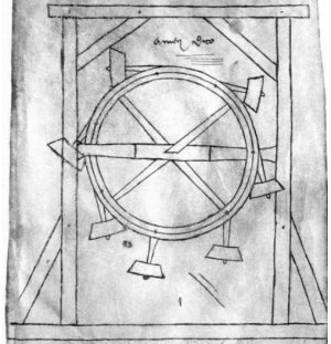
An architect named Villard de Honnecourt drew an impractical perpetual motion machine in the 13th century that was also an overbalanced wheel. His device, and other similar ones, would require a complete lack of friction to work. Even Leonardo da Vinci, who did not think such a device was possible, did some sketches of overbalanced wheels, hoping to find a solution.

Types of Machines

There isn’t just a single kind of perpetual motion machine. A type I machine claims to produce work without any input energy. For example, a wheel that spins for no reason would be a type I machine.

Type II machines violate the second law of thermodynamics. For example, the “zeromoter” — developed in the 1800s by John Gamgee, used ammonia and a piston to move by boiling and cooling ammonia. While the machine was, of course, debunked, Gamgee has the honor of being the inventor of the world’s first mechanically frozen ice rink in 1844.

Type III machines claim to use some means to reduce friction to zero to allow a machine to work that would otherwise run down. For example, you can make a flywheel with very low friction bearings, and with no load, it may spin for years. However, it will still spin down.

Often, machines that claim to be perpetual either don’t really last forever — like the flywheel — or they actually draw power from an unintended source. For example, in 1760, James Cox and John Joseph Merlin developed Cox’s timepiece and claimed it ran perpetually. However, it actually drew power from changes in barometric pressure.

Frauds

These inventions were often mere frauds. E.P. Willis in 1870 made money from his machine but it actually had a hidden source of power. So did John Ernst Worrell Keely’s induction resonance motion motor that actually used hidden air pressure tubes to power itself. Harry Perrigo, an MIT graduate, also demonstrated a perpetual motion machine to the US Congress in 1917. That device had a secret battery.

However, some inventors probably weren’t frauds. Nikola Tesla was certainly a smart guy. He claimed to have found a principle that would allow for the construction of a Type II perpetual motion machine. However, he never built it.

There have been hosts of others, and it isn’t always clear who really thought they had a good idea and how many were just out to make a buck. But some people have created machines as a joke. Dave Jones, in 1981, created a bicycle wheel in a clear container that never stopped spinning. But he always said it was a fake and that he had built it as a joke. Adam Savage looks at that machine in the video below. He wrote his secret in a sealed envelope before he died, and supposedly, only two people know how it works.

Methods

Most perpetual machines try to use force from magnets. Gravity is also a popular agent of action. Other machines depend on buoyancy (like the one in the video below) or gas expansion and condensation.

The US Patent and Trademark Office manual of patent examining practice says:

With the exception of cases involving perpetual motion, a model is not ordinarily required by the Office to demonstrate the operability of a device. If operability of a device is questioned, the applicant must establish it to the satisfaction of the examiner, but he or she may choose his or her own way of so doing.

The UK Patent Office also forbids perpetual motion machine patents. The European Patent Classification system has classes for “alleged perpetua mobilia”

Of course, having a patent doesn’t mean something works; it just means the patent office thought it was original and can’t figure out why it wouldn’t work. Consider Tom Bearden’s motionless electromagnetic generator, which claims to generate power without any external input. Despite widespread denouncement of the supposed operating principle — Bearden claimed the device extracted vacuum energy — the patent office issued a patent in 2002.

The Most Insidious

The best machines are ones that use energy from some source that isn’t apparent. For example, a Crookes radiometer looks like a lightbulb with a little propeller inside. Light makes it move. It is also a common method to use magnetic fields to move something without obviously spinning it. For example, the egg of Columbus (see the video below) is a magnet, and a moving magnetic field makes the egg spin. This isn’t dissimilar from a sealed pump where a magnet turns on the dry side and moves the impeller, which is totally immersed in liquid.

Some low-friction systems, like the flywheel, can seem to be perpetual motion machines if you aren’t patient enough. But eventually, they all wear down.

Crazy or Conspiracy?

Venues like YouTube are full of people claiming to have free energy devices that also claim to be suppressed by “the establishment”. While we hate to be on the wrong side of history if someone does pull it off, we are going to go out on a limb and say that there can’t be a true perpetual motion machine. Unless you cheat, of course.

This is the place we usually tell you to get hacking and come up with something cool. But, sadly, for this time we’ll entreat you to spend your time on something more productive, like a useless box or put Linux on your Commodore 64.


Almost Google Glass in 1993

1 Julio 2024 at 02:00

You might think Google Glass was an innovative idea, but [Allison Marsh] points out that artist [Lisa Krohn] imagined the Cyberdesk in 1993. Despite having desk in the name, the imagined prototype was really a wearable computer. Of course, in 1993, the technology wasn’t there to actually build it, but it does look like [Krohn] predicted headgear that would augment your experience.

Unlike Google Glass, the Cyberdesk was worn like a necklace. There are five disk-like parts that form a four-key keyboard and something akin to a trackpad. There were two models built, but since they were nonfunctional, they could have any imagined feature you might like. For example, the system was supposed to draw power from the sun and your body, something practical devices today don’t really do, either.

She also imagined a wrist-mounted computer with satellite navigation, a phone, and more. Then again, so did [Chester Gould] when he created Dick Tracy. The post also talks about a more modern reimagining of the Cyberdesk last year.

While this wasn’t a practical device, it is a great example of how people imagine the future. Sometimes, they miss the mark, but even then, speculative art and fiction can serve as goals for scientists and engineers who build the actual devices of the future.

We usually think about machines augmenting our intelligence and senses, but maybe we should consider more physical augmentation. We do appreciate seeing designs that are both artistic and functional.

AnteayerSalida Principal

3D Printing with a Twist

30 Junio 2024 at 11:00

When we think about sending an STL off on the Internet for processing, we usually want someone to print it for us or we want mesh repair. But [Chuck] found an interesting project on GitHub from [Andrew Sink] that will let you add a variable amount of twist to any STL and then return it to you for printing or whatever else you use STLs for. If you don’t get what we mean, check out the video below.

The site that does the work initially loads a little gnome figure if you are too lazy to upload your own model. That’s perfect, though, because the little guy is a good example of why you might want to twist a model. With just a little work, you can make the gnome look in one direction or even look behind him.

[Chuck] shows how to use the tool for artistic effect by twisting his standard cube logo. The result is something that looks like it would be difficult to create, but could hardly be easier. The tool lets you rotate the object, too, so you can get the twist effect in the right orientation for what you want to accomplish. A great little tool for making more artistic 3D prints without learning new software. If you want some fun, you can try the version that uses sound from your microphone to control the twist.

If you’d rather twist in CAD, we can help. If you really want artsy 3D printing, you probably need to learn Blender.

3D Printing with Sublime Sublimation

28 Junio 2024 at 23:00

[Teaching Tech] got an interesting e-mail from [Johan] showing pictures of 3D prints with a dye-sublimated color image on the surface. Normally, we think of dye sublimation, we think of pressing color pictures onto fabric, especially T-shirts. But [Johan] uses a modified Epson inkjet printer and has amazing results, as you can see in the video below.

The printers use separate tanks for ink, which seems to be the key. If you already have an Espon “tank” printer, you are halfway there, but if you don’t have one, a cheap one will set you back less than $200 and maybe even less if you pick one up used.

You have to fill bottles with special dye, of course. You can also use the printer to make things like T-shirts. The idea is to print a dye transfer page and place it on the bed before you start printing. The sublimation dye is activated with heat, and, of course, you are shooting out hot plastic, so the image will transfer to the plastic.

[Teaching Tech] explains the best settings to make it all work. The results look great and we’re interested to try this ourselves. Transferring bed images is old hat, but this is something else. Beats liar’s color printing.

8-Bits and 1,120 Triodes

28 Junio 2024 at 02:00

While it’s currently the start of summer in the Northern Hemisphere, it will inevitably get cold again. If you’re looking for a unique way of heating your workshop this year, you could do worse than build an 8-bit computer with a bunch of 6N3P vacuum tubes. While there are some technical details, you might find it a challenging build. But it is still an impressive sight, and it took 18 months to build a prototype and the final version. You can find the technical details if you want to try your hand. Oh, did we mention it takes about 200 amps? One of the prototype computers plays Pong on a decidedly low-tech display, which you can see below.

The architecture has 8 data bits and 12 address bits. It only provides six instructions, but that keeps the tube count manageable. Each tube has two triodes in one envelope and form a NOR gate which is sufficient to build everything else you need. In addition to tubes, there are reed relays and some NVRAM, a modern conceit.

Operating instructions are to turn it on and wait for the 560 tubes to warm up. Then, to quote the designer, “… I check the fire extinguisher is full, and run the code.” We wonder if one of the six instructions is halt and catch fire. Another quote from the builder is: “It has been a ridiculous amount of soldering and a fantastic amount of fun.” We can imagine.

If the computer seems familiar, we covered the first and second prototypes named ENA and Fred. We’ve also seen tube-base single-board computers.

$3 Smartwatch Can Run Python

27 Junio 2024 at 05:00

[Poking Technology] doesn’t think much of his new smartwatch. It is, by his admission, the cheapest possible smartwatch, coming in at about $3. It has very few useful features but he has figured out how to port MicroPython to it, so for a wrist-mounted development board with BLE, it might be useful. You can check it out in the video below.

The first step is a teardown, which reveals surprisingly little on the inside. There’s a tiny battery, a few connections, a display, and a tiny CPU board. There are, luckily, a few test pads that let you get into the CPU. What do you get? A 24 MHz Telink CPU with 512k of flash and 16k of RAM, along with all the other hardware.

Of course, even if you just want a display with some smarts, $3 might be in your price range. The whole thing wound up taped down to a PCB. But the usual debugger didn’t want to connect. Grabbing an oscilloscope revealed that the output from the board had some level problems. He eventually wrote his own debugger interface using a Pi Pico.

He was able to find the onboard CPU’s development tools. The CPU claims to be proprietary but looks suspiciously like a slightly modified ARM. A short investigation shows that the object code is extremely similar to the ARM Thumb instruction set but with a few extra bits set and different mnemonics. But once you put Python on board, who really cares?

The only downside is that it doesn’t appear that the BLE is practically usable because of memory limitations. But there are still places you might use the little watch in a project.

If you want a smartwatch, maybe build your own. While many DIY watches are simple, you can get pretty complicated if you like.

Decoding Meshtastic with GNU Radio

26 Junio 2024 at 20:00

Meshtastic is a way to build mesh networks using LoRa that is independent of cell towers, hot spots or traditional repeaters. It stands to reason that with an SDR and GNU Radio, you could send and receive Meshtastic messages. That’s exactly what [Josh Conway] built, and you can see a video about the project, Meshtastic_SDR, below. The video is from [cemaxecuter], who puts the library through its paces.

For hardware, the video uses a Canary I as well as the WarDragon software-defined radio kit which is an Airspy R2 and a mini PC running Dragon OS — a Linux distribution aimed at SDR work —  in a rugged case. GNU Radio, of course, uses flows which are really just Python modules strung together with a GUI.

The GNU blocks send and receive data via TCP port, so using the radio as a data connection is simple enough. The flow graph itself for the receiver looks daunting, but we have a feeling you won’t change the default very much.

If you’ve wanted to dip your toe into Meshtastic or you want a meaty example of using GNU Radio, this would be a fun project to duplicate and extend. While Meshtastic is generally a mesh protocol, you can set up a node to act as a repeater. You never know when decentralized communications might save the day.

3D Printering: Adaptive Bed Leveling

26 Junio 2024 at 14:00
Art of 3D printer in the middle of printing a Hackaday Jolly Wrencher logo

Have you ever read about something and thought, “Gee whiz! Why did I never think about that?” That was my reaction to reading about a feature commonly associated with Klipper called adaptive bed leveling or adaptive mesh leveling. Too bad I don’t typically use Klipper, but it all worked out, and I’ll show you how it might work for you.

What Is It?

Time to tram your bed!

Once a luxury, most 3D printers now come with some kind of bed level sensor. The idea is that the printer can probe the bed to determine the shape of the build plate and then adjust the build plate accordingly. So if a particular spot on the bed is 0.5 mm too high, the nozzle can rise 0.5 mm when it is in that area. There are several techniques Marlin firmware uses, including what I usually use: UBL. Some people scan the bed once and hope it won’t change much. Others will do a time-consuming scan before each print.

However, adaptive bed leveling is a bit different. The idea is that the printer only probes the area where the part is going to print. If your print bed is 235 mm x 235 mm but your part is 50 mm square, you could just probe the points under the 50 mm square.

This does several things. For a given number of points, there is less motion, so it should be faster. Also, for the same number of points, you will have a much denser mesh and, thus, a better idea of what the bed is at any given point. You could even reduce the number of points based on the size of the part you are printing.

When you think about it, it is a dead simple idea. What’s not to love? For most print jobs, you’ll have less work for the printer, faster prints, and a denser mesh. But how do you do it?

How Do You Do It?

Can you make this work with your printer? Maybe. The trick is you need a way to tell your printer firmware to restrict the mesh area. You also need a way to have the slicer output a bounding box for the part, but that’s usually not hard. If you had to, you could even post process your Gcode and figure that out, but you probably won’t have to.

I

Giving your sensor less distance to travel is a good thing

f you use linear or bilinear leveling, you are in business. That’s because the G29 command for bilinear accepts an L, R, F, and B parameter that lets you set the left, right, front, and back measurements of the probing grid. You can also set the number of probe points with H. Actually, H sets one side of the square, so if H=5, you will probe 25 points in the area.

However, I use UBL, and on one of my printers, I think I’m out of luck without changing something in the firmware. While there is a mesh inset setting, it is set when you build the firmware, so it won’t be practical to change it on the fly.

However, two of my printers are Ender 3 v2 Neo machines. By themselves, they use some odd variant of normal leveling, but I long ago flashed them with the excellent “professional” firmware by [mriscoc]. This is Marlin configured for these machines and — at least the version I use — has UBL set. But, there’s a catch.

The firmware has some custom Gcodes that start with C. C29 sets the mesh size and location very much like other versions. For some reason, it also sets the temperature. Here’s the documentation:

C29 Ln Rn Fn Bn Tn Nn Xn Ym : set probing mesh inset (Left, Right, Front, Back) in mm. T is the probing temperature (T0 doesn’t change the current bed temperature) and N is the density or amount of grid points NxN, it is posible to set a NxM density by using X and Y. In UBL use G29 S# to save to a mesh slot number #.

Try It!

Just as an experiment, I sent the following to the printer via a terminal:

C29 L100 R150 F100 B150 T0 N5

Nothing happened. But when I performed a G29 P1 to probe the bed, it obeyed the new restriction. All that was left was to make the slicer output the correct startup code. Of course, if you are using bilinear levelling, you’ll use G29 instead and have to change a few of the arguments.

Engage Start Up Sequence

Most slicers allow you to put placeholder variables in your Gcode scripts. You may have to look it up for your slicer. There are also plugins that can do the work, but you’d need to change their G29 to C29 (in my case). I mostly use SuperSlicer, which is forked from PrusaSlicer, which is forked from Slic3r.

Here’s part of my startup code:

G28 ; home all
C29 L{first_layer_print_min[0]} R{min(190,first_layer_print_max[0])} F{first_layer_print_min[1]} B{min(180,first_layer_print_max[1])} T0 N5
G29 P1  ; probe
G29 A   ; activate (may not be needed?)
G29 F2  ; Fade height 2mm (or whatever you want)

That’s it. If you have a line that purges your nozzle, you might want to correct it using similar logic or just add a few skirt loops in the slicer and forget about it. Note that I probe 25 points, which might be a bit much for a small part. It would be nice to write a script to detect how big a part is and adjust things. Note that Prusa has enough power to do this totally in the start code, but it would be different in Slic3r or Cura. If you look around, there are a few different examples of doing this for both slicers and various firmware that you will — no doubt — have to adapt to your circumstances.

I need to crack into the firmware for my other printer to see if a similar C command is feasible to add. But that’s for another day, especially since the C29 command is provided as object code only, so I’ll have to start from scratch. Luckily, I’m used to building (and rebuilding) Marlin for all the machines, especially that one, since it is a custom blend of many parts. I may switch out to bilinear leveling. Or, I could break down and go to Klipper, I suppose.

We want to try fast scanning next. Of course, things are simple if you tram your flat bed once and forget it. That is until something changes.

All About CRTs

26 Junio 2024 at 05:00

For old-timers, CRTs — cathode ray tubes — were fixtures as kids sat in front of TVs watching everything from Howdy Doody to Star Trek. But there’s at least one generation that thinks TVs and computer monitors are flat. If that describes you, you might enjoy [The 8-Bit Guy’s] coverage of how CRTs work in the video below.

CRTs were heavy, took high voltage, and had a dangerous vacuum inside, so we really don’t miss them. The phosphor on the screen had a tendency to “burn in” if you showed the same image over and over. We don’t miss that either.

The basic idea is simple. An electron is fired at the phosphor behind the screen. An electrostatic or electromagnetic arrangement allows you to hit specific spots on the screen, and, of course, you can turn the beam off. Color CRTs have three different phosphors, and the beams have to fire at the correct color phosphor.

The best part of the video is the part where they tear apart an actual CRT, something you don’t see very often. We were worried about the vacuum, but the tube in question had already vented to atmosphere.

We doubt CRTs will make a comeback like vinyl records have. If so, maybe you’ll settle for a software simulation. It does make retrocomputing simulators feel better.

3D Scanning, Phone Edition

25 Junio 2024 at 23:00

It seems to make sense. If you have a 3D printer, you might wish you could just scan some kind of part and print it — sort of like a 3D photocopier. Every time we think about this, though, we watch a few videos and are instantly disappointed by the results, especially with cheap scanners. If you go the hardware route, even cheap is relative. However, you can — in theory — put an app on your phone to do the scanning. Some of the apps are free, and some have varying costs, but, again, it seems like a lot of work for an often poor result. So we were very interested in the video from [My 3D Print Lab] where he uses his phone and quite a few different apps and objectively compares them.

Unsurprisingly, one of the most expensive packages that required a monthly or annual subscription created an excellent scan. He didn’t print from it, though, because it would not let you download any models without a fee. The subject part was an ornate chess piece, and the program seems to have captured it nicely. He removed the background and turntable he was using with no problems.

Other apps didn’t fare as well, either missing some of the parts or failing to omit background elements. You may have to do some post-processing. Some of the other expensive options have free trials or other limits, but you can at least try them for free. One of the free trials let you do three free scans, but each scan took about 8 hours to process.

There are some free options, too, and while they aren’t great, most of the paid ones aren’t very good either. The apps tested are: Widar, Polycam, xOne, RealityScan, MagiScan, Qlone, Kiri Engine, and MakerWorld AI Scanner. Not all of these would provide a free download, but for the ones that did, he tried to print the resulting model from each. Qlone didn’t work on Android, so it didn’t get tested either.

Of the phone apps, Kiri Engine looks like the best. However, he also shows MakerWorld AI Scanner, a Web app that converts videos. It had a few minor issues, but it did a great job and looks like something that might be fun to try, especially since it is free. They also have a tool on that same website that has a limited number of uses per month that claims it can create a 3D model from a single photograph (and not just an extrusion of the flat image). There’s some science behind that.

If you just want the results, you can skip to about 14:50 to learn the reasoning behind the top three picks in each evaluation category. We know sometimes it is just as easy to design a part as scan it. We’ve used one of those cheap turntable scanners before, but they have gotten somewhat better recently.

The Book That Could Have Killed Me

24 Junio 2024 at 14:00

It is funny how sometimes things you think are bad turn out to be good in retrospect. Like many of us, when I was a kid, I was fascinated by science of all kinds. As I got older, I focused a bit more, but that would come later. Living in a small town, there weren’t many recent science and technology books, so you tended to read through the same ones over and over. One day, my library got a copy of the relatively recent book “The Amateur Scientist,” which was a collection of [C. L. Stong’s] Scientific American columns of the same name. [Stong] was an electrical engineer with wide interests, and those columns were amazing. The book only had a snapshot of projects, but they were awesome. The magazine, of course, had even more projects, most of which were outside my budget and even more of them outside my skill set at the time.

If you clicked on the links, you probably went down a very deep rabbit hole, so… welcome back. The book was published in 1960, but the projects were mostly from the 1950s. The 57 projects ranged from building a telescope — the original topic of the column before [Stong] took it over — to using a bathtub to study aerodynamics of model airplanes.

X-Rays

[Harry’s] first radiograph. Not bad!
However, there were two projects that fascinated me and — lucky for me — I never got even close to completing. One was for building an X-ray machine. An amateur named [Harry Simmons] had described his setup complaining that in 23 years he’d never met anyone else who had X-rays as a hobby. Oddly, in those days, it wasn’t a problem that the magazine published his home address.

You needed a few items. An Oudin coil, sort of like a Tesla coil in an autotransformer configuration, generated the necessary high voltage. In fact, it was the Ouidn coil that started the whole thing. [Harry] was using it to power a UV light to test minerals for flourescence. Out of idle curiosity, he replaced the UV bulb with an 01 radio tube. These old tubes had a magnesium coating — a getter — that absorbs stray gas left inside the tube.

The tube glowed in [Harry’s] hand and it reminded him of how an old gas-filled X-ray tube looked. He grabbed some film and was able to image screws embedded in a block of wood.

With 01 tubes hard to find, why not blow your own X-ray tubes?

However, 01 tubes were hard to get even then. So [Harry], being what we would now call a hacker, took the obvious step of having a local glass blower create custom tubes to his specifications.

Given that I lived where the library barely had any books published after 1959, it is no surprise that I had no access to 01 tubes or glass blowers. It wasn’t clear, either, if he was evacuating the tubs or if the glass blower was doing it for him, but the tube was down to 0.0001 millimeters of mercury.

Why did this interest me as a kid? I don’t know. For that matter, why does it interest me now? I’d build one today if I had the time. We have seen more than one homemade X-ray tube projects, so it is doable. But today I am probably able to safely operate high voltages, high vaccums, and shield myself from the X-rays. Probably. Then again, maybe I still shouldn’t build this. But at age 10, I definitely would have done something bad to myself or my parent’s house, if not both.

Then It Gets Worse

The other project I just couldn’t stop reading about was a “homemade atom smasher” developed by [F. B. Lee]. I don’t know about “atom smasher,” but it was a linear particle accelerators, so I guess that’s an accurate description.

The business part of the “atom smasher” (does not show all the vacuum equipment).

I doubt I have the chops to pull this off today, much less back then. Old refigerator compressors were run backwards to pull a rough vaccuum. A homemade mercury diffusion pump got you the rest of the way there. I would work with some of this stuff later in life with scanning electron microscopes and similar instruments, but I was buying them, not cobbling them together from light bulbs, refigerators, and home-made blown glass!

You needed a good way to measure low pressure, too, so you needed to build a McLeod gauge full of mercury. The accelerator itself is three foot long,  borosilicate glass tube, two inches in diameter. At the top is a metal globe with a peephole in it to allow you to see a neon bulb to judge the current in the electron beam. At the bottom is a filament.

The globe at the top matches one on top of a Van de Graf generator that creates about 500,000 volts at a relatively low current. The particle accelerator is decidedly linear but, of course, all the cool particle accelerators these days form a loop.

[Andres Seltzman] built something similar, although not quite the same, some years back and you can watch it work in the video below:

What could go wrong? High vacuum, mercury, high voltage, an electron beam and plenty of unintentional X-rays. [Lee] mentions the danger of “water hammers” in the mercury tubes. In addition, [Stong] apparently felt nervous enough to get a second opinion from [James Bly] who worked for a company called High Voltage Engineering. He said, in part:

…we are somewhat concerned over the hazards involved. We agree wholeheartedly with his comments concerning the hazards of glass breakage and the use of mercury. We feel strongly, however, that there is inadequate discussion of the potential hazards due to X-rays and electrons. Even though the experimenter restricts himself to targets of low atomic number, there will inevitably be some generation of high-energy X-rays when using electrons of 200 to .300 kilovolt energy. If currents as high as 20 microamperes are achieved, we are sure that the resultant hazard is far from negligible. In addition, there will be substantial quantities of scattered electrons, some of which will inevitably pass through the observation peephole.

I Survived

Clearly, I didn’t build either of these, because I’m still here today. I did manage to make an arc furnace from a long-forgotten book. Curtain rods held carbon rods from some D-cells. The rods were in a flower pot packed with sand. An old power cord hooked to the curtain rods, although one conductor went through a jar of salt water, making a resistor so you didn’t blow the fuses.

Somehow, I survived without dying from fumes, blinding myself, or burning myself, but my parent’s house had a burn mark on the floor for many years after that experiement.

If you want to build an arc furnace, we’d start with a more modern concept. If you want a safer old book to read, try the one by [Edmund Berkeley], the developer of the Geniac.

Fixed Point Math Exposed

23 Junio 2024 at 11:00

If you are used to writing software for modern machines, you probably don’t think much about computing something like one divided by three. Modern computers handle floating point quite well. However, in constrained systems, there is a trap you should be aware of. While modern compilers are happy to let you use and abuse floating point numbers, the hardware is often woefully slow. It also tends to eat up lots of resources. So what do you do? Well, as [Low Byte Productions] explains, you can opt for fixed-point math.

In theory, the idea is simple. Just put an arbitrary decimal point in your integers. So, for example, if we have two numbers, say 123 and 456, we could remember that we really mean 1.23 and 4.56. Adding, then, becomes trivial since 123+456=579, which is, of course, 5.79.

But, of course, nothing is simple. Multiplyting those two numbers gives you 56088 but that’s 5.6088 and not 560.88. So keeping track of the decimal point is a little more complicated than the addition case would make you think.

How much more complicated is it? Well, the video covers a lot but it takes an hour and half to do it. There’s plenty of code and explanations so if you haven’t dealt with fixed point math or you want a refresher, this video’s worth the time to watch.

Want to do 3D rendering on an ATMega? Fixed point is your friend. We’ve done our own deep dive on the topic way back in 2016.

Clearly 3D Printing

23 Junio 2024 at 05:00

[Joel] picked up a wireless mouse kit. The idea is you get some 3D printing files and hardware. You can print the shell or make modifications to it. You can even design your own shell from scratch. But [Joel] took a different approach. He created a case with transparent resin. You can see the impressive result in the video below.

While the idea of buying the mouse as a kit simplifies things, we would be more inclined to just gut a mouse and design a new case for it if we were so inclined. We were more impressed with the results with the transparent resin.

Having transparent 3D printing capabilities opens up some artistic possibilities, like the benchy inside a glass bottle that makes a guest appearance on the video. The only limitation we can see is that your entire print has to be clear unless you do some hacky workarounds. For example, it would have been cool to have a mouse that was only transparent through a window. Short of painting the finished product, this would be tough to do with modern printers.

Even though you can get transparent filament, FDM printers have to work hard to get even sort of transparent. Even then, the results can be impressive, but nothing like what [Joel] is doing in resin, of course.

In Future, Printer Documents You

23 Junio 2024 at 02:00

[Jason Dookeran] reminded us of something we don’t like to think about. Your printer probably adds barely noticeable dots to everything you print. It does it on purpose, so that if you print something naughty, the good guys can figure out what printer it came from. This is the machine identification code and it has been around since the days that the US government feared that color copiers would allow wholesale counterfiting.

The technology dates back to Xerox and Canon devices from the mid-80s, but it was only publicly acknowledged in 2004. With color printers, the MIC — machine identification code — is a series of tiny yellow dots. Typically, each dock is about 10 microns across and spaced about a millimeter from each other. The pattern prints all over the page so that even a fragment of, say, a ransom note can be identified.

Apparently, printers use different encoding schemes, but reading the dots is usually done by scanning them under a blue light.

The EFF has an out-of-date list that identifies many printers that track. But they point out that some printers may use a different method, especially those that can’t print yellow. They also mention that it is likely that “all recent commercial color laser printers” print some kind of code.

If you want to check your printer, [Jason] points out an Instructable and a website that can decode common patterns.

While we can think of times we are glad people can figure out the origin of a death threat or a ransom note, we can also think of times when we would like whistleblowers or people with different opinions to be able to print things without fear of retribution. But either way, the technology is an interesting real-world example of steganography.

We prefer these yellow dots. Yellow steganography reminds us of turmeric.

Title image: “Yellow dots produced by an HP Color LaserJet CP1515n” CC BY-SA 3.0 by [Ianusisu].

Vintage Hacks for Dot Matrix Printers in China

22 Junio 2024 at 05:00

In an excerpt from his book The Chinese Computer: A Global History of the Information Age, [Thomas Mullaney] explains how 1980s computer tech — at least the stuff that was developed in the West — was stubbornly rooted in the Latin alphabet. After all, ASCII was king, and with 60,000 symbols, Chinese was decidedly difficult to shoehorn into 8 bits. Unicode was years in the future so, of course, ingenious hackers did what they do best: hack!

The subject of the post is the dot matrix printer. Early printers had nine pins, which was sufficient to make Latin characters in one pass. To print Chinese, each character required at least two passes of the print head. This was slow, of course, but it was also subject to confusing variations due to ink inconsistency and registration problems. It also made the Chinese characters twice as big as English text.

Initial attempts were made to use finer pins to pack twice as many dots in the same space. But this made the pins too thin and subject to bending and breaking. Instead, some engineers would retain the two passes but move the print head just slightly lower so the second pass left dots in the gaps between the first pass dots. Obviously, the first pass would print even-numbered dots (0, 2, 4,…), and the second pass would catch the odd-numbered dots. This wasn’t faster, of course, but it did produce better-looking characters.

While international languages still sometimes pose challenges, we’ve come a long way, as you can tell from this story. Of course, Chinese isn’t the only non-Latin language computers have to worry about.

Build Your Own Tape Recorder/Player

21 Junio 2024 at 23:00

If you want to read something from magnetic tape, you need a tape head, right? Or you could do like [Igor Brichkov] and make your own. It looks surprisingly simple. He used a washer with a small slot cut in it and a coil of wire.

The first experiment, in the first video below, is using a commercial tape head connected to a preamp. Music playing “through” the homemade head is readable by the commercial tape reader. This is a prelude to creating an entire tape deck using the head, which you can see in the second video below.

The homemade deck is a collection of small protoboards along with some hodgepodge components, a Bluetooth board, and aluminum foil shielding. One of the protoboards has a simple VU meter using eight LEDs.

We aren’t sure what possessed [Igor] to want to make a tape deck, and — to be fair — it looks like he borrowed the transport mechanism from a commercial player. But we never really need an excuse to build something cool, so we appreciate him sharing his DIY tape deck with us and the world.

If you want to know just about anything related to tape decks, we have some suggested reading for you. If you have trouble finding parts for your cassette collection, maybe fire up your 3D printer.

Is That a Large Smartwatch? Or a Tiny Cray?

21 Junio 2024 at 08:00

While we aren’t typically put off by a large wristwatch, we were taken a bit aback by [Chris Fenton]’s latest timepiece — if you can call it that. It’s actually a 1/25th-scale Cray C90 worn as a wristwatch. The whole thing started with [Chris] trying to build a Cray in Verilog. He started with a Cray-1 but then moved to a Cray X-MP, which is essentially a Cray-1 with two extra address bits. Then he expanded it to 32 bits, which makes it a Cray Y-MP/C90/J90 core. As he puts it, “If you wanted something practical, go read someone else’s blog.”

The watch emulates a Cray C916 and uses a round OLED display on the top. While the move from 22 to 32 address bits sounds outdated, keep in mind the Cray addresses 64-bit words exclusively, so we’re talking access to 32 gigabytes of memory. The hardware consists of an off-the-shelf FPGA board and a Teensy microcontroller to handle mundane tasks like driving the OLED display and booting the main CPU. Interestingly, the actual Cray 1A used Data General computers for a similar task.

Of course, any supercomputer needs a super program, so [Chris] uses the screen to display a full simulation of Jupiter and 63 of its moons. The Cray excels at programs like this because of its vector processing abilities. The whole program is 127 words long and sustains 40 MFLOPs. Of course, that means to read the current time, you need to know where Jupiter’s moons are at all times so you can match it with the display. He did warn us this would not be practical.

While the Cray wouldn’t qualify as a supercomputer today, we love learning about what was state-of-the-art not that long ago. Cray was named, of course, after [Seymour Cray] who had earlier designed the Univac 1103, several iconic CDC computers, and the Cray computers, of course.

Adding Texture to 3D Prints

20 Junio 2024 at 23:00

[3DJake] likes putting textures on 3D prints using things like patterned build plates and fuzzy skin. However, both of those techniques have limitations. The build plate only lets you texture the bottom, and the fuzzy skin texture isn’t easy to control. So he shows how to use Blender to create specific textures to produce things like wood-like or leather-like surfaces, for example. You can see how it works in the video below.

As [Jake] points out, you might be able to use other artistic programs to do this, but the kind of things we use like FreeCAD of Fusion360 aren’t going to cut it.

He uses a bag with a leather texture as an example. The resulting model is too detailed and contains around 1.4 million triangles. Your printer isn’t that detailed, and your slicer will probably choke on a model with that many triangles. Decimating the model makes it more manageable.

The resulting bags, when printed using TPU and painted, hardly look like 3D prints. Well, other than the strap, perhaps. The textures were just pulled from the Internet, so there are, potentially, many to choose from as long as they are seamless.

One interesting build plate texture is a diffraction grating. You can also add special textures manually. Textures are good at hiding layer lines, even just the fuzzy skin textures you find in many slicers.

What You Can See with a SEM?

20 Junio 2024 at 05:00

The last time we used a scanning electron microscope (a SEM), it looked like something from a bad 1950s science fiction movie. These days SEMs, like the one at the IBM research center, look like computers with a big tank poised nearby. Interestingly, the SEM is so sensitive that it has to be in a quiet room to prevent sound from interfering with images.

As a demo of the machine’s impressive capability, [John Ott] loads two US pennies, one facing up and one face down. [John] notes that Lincoln appears on both sides of the penny and then proves the assertion correct using moderate magnification under the electron beam.

Some electron microscopes pass electrons through thin samples much as light passes through a sample on a microscope slide. However, SEMs and REMs (reflection electron microscopes) use either secondary electron emission or reflected electrons from the surface of items like the penny.

You often see SEMs also fitted with EDS — energy dispersive X-ray spectrometers, sometimes called EDX — that can reveal the composition of a sample’s surface. There are other ways to examine surfaces, like auger spectrometers (pronounced like OJ), which can isolate thin films on surfaces. There’s also SIMS (secondary ion mass spectrometry) which mills bits of material away using an ion beam. and Rutherford backscattering spectrometry, which also uses an ion beam.

We keep waiting for someone to share plans to make a cheap, repeatable SEM. There are a few attempts out there, but we don’t see many in the wild. While the device is conceptually simple, you do need precise high voltages and high vacuums,. Also, you frequently need ancillary devices to do things like sputter gold in argon gas to coat nonconductive samples, so the barrier to entry is high.

❌
❌