Supercon 2024 SAO Petal KiCad Redrawing Project
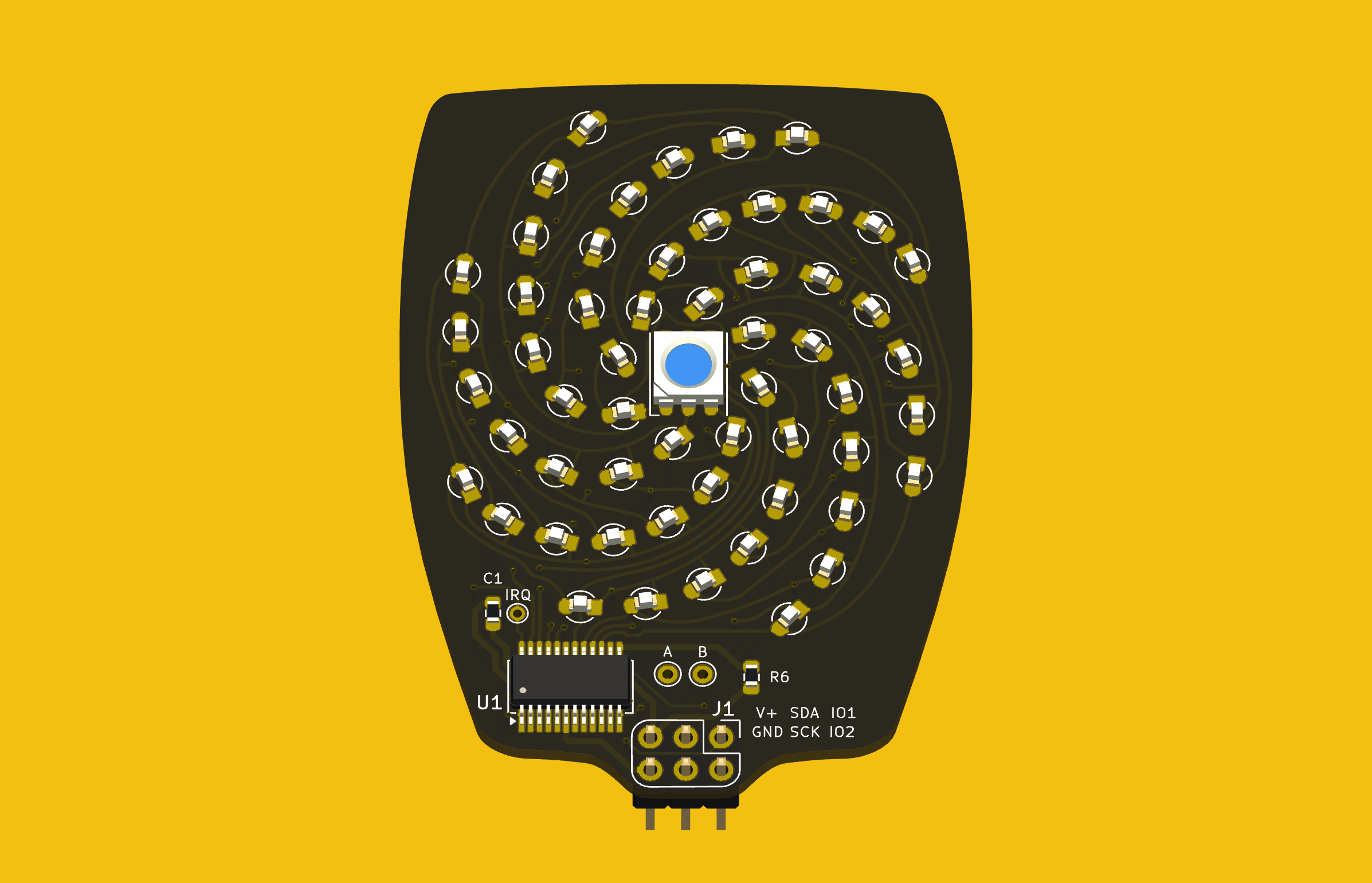
Last week I completed the SAO flower badge redrawing task, making a complete KiCad project. Most of the SAO petals are already released as KiCad projects, except for the Petal Matrix. The design features 56 LEDs arranged in eight spiral arms radiating from the center. What it does not feature are straight lines, right angles, nor parts placed on a regular grid.
Importing into KiCad
Grep Those Positons
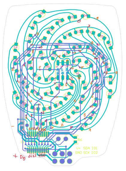
I first wanted to only read the data from the LEDs for analysis, and I didn’t need the full Kicad + Python scripting for that. Using grep on the PCB file, you get a text file that can be easily parsed to get the numbers. I confirmed that the LED placements were truly as irregular as they looked.
My biggest worry was how obtain and re-apply the positions and angles of the LEDs, given the irregular layout of the spiral arms. Just like the random angles of six SAO connector on the badge board, [Voja] doesn’t disappoint on this board, either. I fired up Python and used Matplotlib to get a visual perspective of the randomness of the placements, as one does. Due to the overall shape of the arms, there is a general trend to the numbers. But no obvious equation is discernable.
It was obvious that I needed a script of some sort to locate 56 new KiCad LED footprints onto the board. (Spoiler: I was wrong.) Theoretically I could have processed the PCB text file with bash or Python, creating a modified file. Since I only needed to change a few numbers, this wasn’t completely out of the question. But that is inelegant. It was time to get familiar with the KiCad + Python scripting capabilities. I dug in with gusto, but came away baffled.
KiCad’s Python Console to the Rescue — NOT
This being a one-time task for one specific PCB, writing a KiCad plugin didn’t seem appropriate. Instead, hacking around in the KiCad Python console looked like the way to go. But I didn’t work well for quick experimenting. You open the KiCad PCB console within the PCB editor. But when the console boots up, it doesn’t know anything about the currently loaded PCB. You need to import the Kicad Python interface library, and then open the PCB file. Also, the current state of the Python REPL and the command history are not maintained between restarts of KiCad. I don’t see any advantages of using the built-in Python console over just running a script in your usual Python environment.
Clearly there is a use case for this console. By all appearances, a lot of effort has gone into building up this capability. It appears to be full of features that must be valuable to some users and/or developers. Perhaps I should have stuck with it longer and figured it out.
KiCad Python Script Outside KiCad
This seemed like the perfect solution. The buzz in the community is that modern KiCad versions interface very well with Python. I’ve also been impressed with the improved KiCad project documentation on recent years. “This is going to be easy”, I thought.
First thing to note, the KiCad v8 interface library works only with Python 3.9. I run pyenv on my computers and already have 3.9 installed — check. However, you cannot just do a pip install kicad-something-or-other... to get the KiCad python interface library. These libraries come bundled within the KiCad distribution. Furthermore, they only work with a custom built version of Python 3.9 that is also included in the bundle. While I haven’t encountered this situation before, I figured out you can make pyenv point to a Python that has been installed outside of pyenv. But before I got that working, I made another discovery.
The Python API is not “officially” supported. KiCad has announced that the current Simplified Wrapper and Interface Generator-based Python interface bindings are slated to be deprecated. They are to be replaced by Inter-Process Communication-based bindings in Feb 2026. This tidbit of news coincided with learning of a similar 3rd party library.
Introducing KiUtils
Many people were asking questions about including external pip-installed modules from within the KiCad Python console. This confounded my search results, until I hit upon someone using the KiUtils package to solve the same problem I was having. Armed with this tool, I was up and running in no time. To be fair, I susepct KiUtils may also break when KiCad switched from SWIG to IPC interface, but KiUtils was so much easier to get up and running, I stuck with it.
I wrote a Python script to extract all the information I needed for the LEDs. The next step was to apply those values to the 56 new KiCad LED footprints to place each one in the correct position and orientation. As I searched for an example of writing a PCB file from KiUtils, I saw issue #113, “Broken as of KiCAD 8?”, on the KiUtils GitHub repository. Looks like KiUtils is already broken for v8 files. While I was able to read data from my v8 PCB file, it is reported that KiCad v8 cannot read files written by KiUtils.
Scripting Not Needed — DOH
At a dead end, I was about to hand place all the LEDs manually when I realized I could do it from inside KiCad. My excursions into KiCad and Python scripting were all for naught. The LED footprints had been imported from Altium Circuit Maker as one single footprint per LED (as opposed to some parts which convert as one footprint per pad). This single realization made the problem trivial. I just needed to update footprints from the library. While this did require a few attempts to get the cathode and anodes sorted out, it was basically solved with a single mouse click.
Those Freehand Traces
The imported traces on this PCB were harder to cleanup than those on the badge board. There were a lot of disconinuities in track segments. These artifacts would work fine if you made a real PCB, but because some segment endpoints don’t precisely line up, KiCad doesn’t know they belong to the same net. Here is how these were fixed:
- Curved segments endpoints can’t be dragged like a straight line segment can. Solutions:
- If the next track is a straight line, drag the line to connect to the curved segment.
- If the next track is also a curve, manually route a very short track between the two endpoints.
- If you route a track broadside into a curved track, it will usually not connect as far as KiCad is concerned. The solution is to break the curved track at the desired intersection, and those endpoints will accept a connection.
- Some end segments were not connected to a pad. These were fixed by either dragging or routing a short trace.
Applying these rules over and over again, I finaly cleared all the discontinuities. Frustratingly, the algorithm to do this task already exists in a KiCad function: Tools -> Cleanup Graphics... -> Fix Discontinuities in Board Outline, and an accompanying tolerance field specified as a length in millimeters. But this operation, as noted in the its name, is restricted to lines on the Edge.Cuts layer.
PCB vs Picture
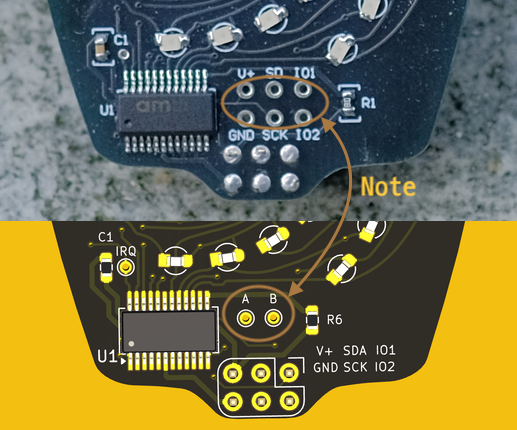
When I was all done, I noticed a detail in the photo of the Petal Matrix PCB assembly from the Hackaday reveal article. That board (sitting on a rock) has six debugging / expansion test points connected to the six pins of the SAO connector. But in the Altium Circuit Maker PCB design, there are only two pads, A and B. These connect to the two auxiliary input pins of the AS1115 chip. I don’t know which is correct. (Editor’s note: they were just there for debugging.) If you use this project to build one of these boards, edit it according to your needs.
Conclusion
The SAO Petal Matrix redrawn KiCad project can be found over at this GitHub repository. It isn’t easy to work backwards using KiCad from the PCB to the schematic. I certainly wouldn’t want to reverse engineer a 9U VME board this way. But for many smaller projects, it isn’t an unreasonable task, either. You can also use much simpler tools to get the job done. Earlier this year over on Hackaday.io, user [Skyhawkson] did a gread job backing out schematics from an Apollo-era PCB with Microsoft Paint 3D — a tool released in 2017 and just discontinued last week.