Vista Normal

Hay nuevos artículos disponibles. Pincha para refrescar la página.
Ayer — 2 Julio 2025Salida Principal

Why The Latest Linux Kernel Won’t Run On Your 486 And 586 Anymore

Por: Lewin Day
2 Julio 2025 at 14:00

Some time ago, Linus Torvalds made a throwaway comment that sent ripples through the Linux world. Was it perhaps time to abandon support for the now-ancient Intel 486? Developers had already abandoned the 386 in 2012, and Torvalds openly mused if the time was right to make further cuts for the benefit of modernity.

It would take three long years, but that eventuality finally came to pass. As of version 6.15, the Linux kernel will no longer support chips running the 80486 architecture, along with a gaggle of early “586” chips as well. It’s all down to some housekeeping and precise technical changes that will make the new code inoperable with the machines of the past.

Why Won’t It Work Anymore?

The kernel has had a method to emulate the CMPXCH8B instruction for some time, but it will now be deprecated.

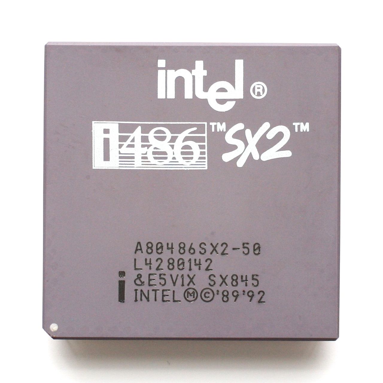
The big change is coming about thanks to a patch submitted by Ingo Molnar, a long time developer on the Linux kernel. The patch slashes support for older pre-Pentium CPUs, including the Intel 486 and a wide swathe of third-party chips that fell in between the 486 and Pentium generations when it came to low-level feature support.

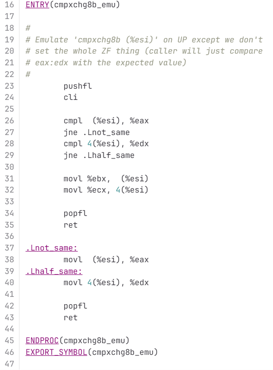
Going forward, Molnar’s patch reconfigures the kernel to require CPUs have hardware support for the Time Stamp Counter (RDTSC) and CMPXCHG8B instructions. These became part of x86 when Intel introduced the very first Pentium processors to the market in the early 1990s. The Time Stamp Counter is relatively easy to understand—a simple 64-bit register that stores the number of cycles executed by the CPU since last reset. As for CMPXCHG8B, it’s used for comparing and exchanging eight bytes of data at a time. Earlier Intel CPUs got by with only the single-byte CMPXCHG instruction. The Linux kernel used to feature a piece of code to emulate CMPXCHG8B in order to ease interoperability with older chips that lacked the feature in hardware.

The changes remove around 15,000 lines of code. Deletions include code to emulate the CMPXCHG8B instruction for older processors that lacked the instruction, various emulated math routines, along with configuration code that configured the kernel properly for older lower-feature CPUs.

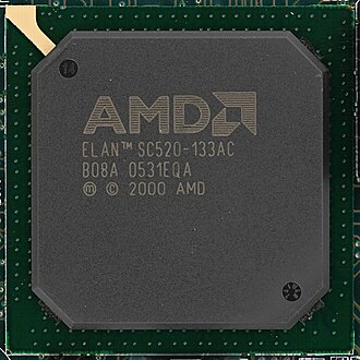
Basically, if you try to run Linux kernel 6.15 on a 486 going forward, it’s just not going to work. The kernel will make calls to instructions that the chip has never heard of, and everything will fall over. The same will be true for machines running various non-Pentium “586” chips, like the AMD 5×86 and Cyrix 5×86, as well as the AMD Elan. It’s likely even some later chips, like the Cyrix 6×86, might not work, given their questionable or non-existent support of the CMPXCHG8B instruction.

Why Now?

Molnar’s reasoning for the move was straightforward, as explained in the patch notes:

In the x86 architecture we have various complicated hardware emulation
facilities on x86-32 to support ancient 32-bit CPUs that very very few
people are using with modern kernels. This compatibility glue is sometimes
even causing problems that people spend time to resolve, which time could
be spent on other things.

Indeed, it follows on from earlier comments by Torvalds, who had noted how development was being held back by support for the ancient members of Intel’s x86 architecture. In particular, the Linux creator questioned whether modern kernels were even widely compatible with older 486 CPUs, given that various low-level features of the kernel had already begun to implement the use of instructions like RDTSC that weren’t present on pre-Pentium processors. “Our non-Pentium support is ACTIVELY BUGGY AND BROKEN right now,” Torvalds exclaimed in 2022. “This is not some theoretical issue, but very much a ‘look, ma, this has never been tested, and cannot actually work’ issue, that nobody has ever noticed because nobody really cares.”

Intel kept i486 chips in production for a good 18 years, with the last examples shipped out in September 2007. Credit: Konstantin Lanzet, CC BY-SA 3.0

Basically, the user base for modern kernels on old 486 and early “586” hardware was so small that Torvalds no longer believed anyone was even checking whether up-to-date Linux even worked on those platforms anymore. Thus, any further development effort to quash bugs and keep these platforms supported was unjustified.

It’s worth acknowledging that Intel made its last shipments of i486 chips on September 28, 2007. That’s perhaps more recent than you might think for a chip that was launched in 1989. However, these chips weren’t for mainstream use. Beyond the early 1990s, the 486 was dead for desktop users, with an IBM spokesperson calling the 486 an “ancient chip” and a “dinosaur” in 1996. Intel’s production continued on beyond that point almost solely for the benefit of military, medical, industrial and other embedded users.

Third-party chips like the AMD Elan will no longer be usable, either. Credit: Phiarc, CC-BY-SA 4.0

If there was a large and vocal community calling for ongoing support for these older processors, the kernel development team might have seen things differently. However, in the month or so that the kernel patch has been public, no such furore has erupted. Indeed, there’s nothing stopping these older machines still running Linux—they just won’t be able to run the most up-to-date kernels. That’s not such a big deal.

While there are usually security implications around running outdated operating systems, the simple fact is that few to no important 486 systems should really be connected to the Internet anyway. They lack the performance to even load things like modern websites, and have little spare overhead to run antiviral software or firewalls on top of whatever software is required for their main duties. Operators of such machines won’t be missing much by being stuck on earlier revisions of the kernel.

Ultimately, it’s good to see Linux developers continuing to prune the chaff and improve the kernel for the future. It’s perhaps sad to say goodbye to the 486 and the gaggle of weird almost-Pentiums from other manufacturers, but if we’re honest, few to none were running the most recent Linux kernel anyway. Onwards and upwards!

Adding Automatic Emergency Braking To An RC Car

Por: Lewin Day
2 Julio 2025 at 08:00

Modern RC cars can be pretty darn fast. That’s fun and all, but it also makes it easy to crash them into things. This problem inspired [Narrow Studios] to whip up something to offer a bit of protection.

The concept is simple enough—the RC car just needs some way to detect obstacles and stop before hitting them. The build relies on ultrasonic sensors as rangefinders to spot solid objects in the path of the vehicle. An Arduino Nano is in charge of reading the sensors. When it appears the car is approaching a wall or similar obstacle, it fires off a PWM signal to the car’s motor controller commanding it to brake. The additional hardware is held to the car with a bunch of custom printed brackets.

The setup isn’t perfect; the video notes that if you insist on accelerating quickly when close to a wall, you still have a fair chance of hitting it. That’s largely put down to the refresh time of the sensors and the overall system, which could be improved with further work. Still, if you’re always crashing your RC car into walls or curbs, this kind of thing might appeal to you.

We’ve featured some other great RC projects before, too.

There Are Better Lego-Compatible Universal Joints Out There

Por: Lewin Day
1 Julio 2025 at 20:00

Lego’s Technic line features all kinds of mechanical devices, from cogs to gears to chains and even pneumatic components. However, the vast majority of these components are made out of plastic and are only capable of toy-like levels of performance. In the competitive world of Lego YouTube, builders often push these parts to their limits, breaking them more often than you might think. To that end, [Brick Experiment Channel] has been investigating stouter Lego-compatible universal joints from a variety of third-party manufacturers.

The video starts with a simple demonstration, showing that a Lego universal joint pops apart at just 0.4 Nm of torque. It’s no surprise, given it relies on tiny plastic pins in snap-fit joints. However, this means that it’s not that hard to build a stronger universal joint to outperform the stock parts.

The video steps through a range of other options available on the market. For example, CaDA builds a universal joint using aluminium sleeves, a copper center, and steel pins to join everything together. It’s so strong that the plastic Lego axles fail long before the joint does. Tested with third-party aluminum axles, it eventually fails at 2.3 Nm of torque when the aluminum sleeve snaps. An all-steel joint from MTP goes even harder, eventually stripping out its axle mount at 4 Nm. The rest of the video goes on to explore angular performance, size, and other design features.

It’s fair to say that if you’re swapping out universal joints and axles for aluminum steel parts, you’re not really playing with Lego anymore. At the same time, it’s neat that there exists a sort of defacto standard kit for mechanical experimentation that is now being expanded upon with stronger components. Video after the break.

AnteayerSalida Principal

One Laptop Manufacturer Had To Stop Janet Jackson Crashing Laptops

Por: Lewin Day
1 Julio 2025 at 14:00

There are all manner of musical myths, covering tones and melodies that have effects ranging from the profound to the supernatural. The Pied Piper, for example, or the infamous “brown note.”

But what about a song that could crash your laptop just by playing it? Even better, a song that could crash nearby laptops in the vicinity, too? It’s not magic, and it’s not a trick—it was just a punchy pop song that Janet Jackson wrote back in 1989.

Rhythm Nation

As told by Microsoft’s Raymond Chen, the story begins in the early 2000s during the Windows XP era. Engineers at a certain OEM laptop manufacturer noticed something peculiar. Playing Janet Jackson’s song Rhythm Nation through laptop speakers would cause the machines to crash. Even more bizarrely, the song could crash nearby laptops that weren’t even playing the track themselves, and the effect was noted across laptops of multiple manufacturers.

Rhythm Nation was a popular song from Jackson’s catalog, but nothing about it immediately stands out as a laptop killer. 

After extensive testing and process of elimination, the culprit was identified as the audio frequencies within the song itself. It came down to the hardware of the early 2000s laptops in question. These machines relied on good old mechanical hard drives. Specifically, they used 2.5-inch 5,400 RPM drives with spinning platters, magnetic heads, and actuator arms.

The story revolves around 5,400 RPM laptop hard drives, but the manufacturer and model are not public knowledge. No reports have been made of desktop PCs or hard disks suffering the same issue. Credit: Raimond Spekking, CC BY-SA 4.0

Unlike today’s solid-state drives, these components were particularly susceptible to physical vibration. Investigation determined that something in Rhythm Nation was hitting a resonant frequency of some component of the drive. When this occurred, the drive would be disturbed enough that read errors would stack up to the point where it would trigger a crash in the operating system. The problem wasn’t bad enough to crash the actual hard drive head into the platters themselves, which would have created major data loss. It was just bad enough to disrupt the hard drive’s ability to read properly, to the point where it could trigger a crash in the operating system.

A research paper published in 2018 investigated the vibrational characteristics of a certain model of 2.5-inch laptop hard drive. It’s not conclusive evidence, and has nothing to do with the Janet Jackson case, but it provides some potentially interesting insights as to why similar hard drives failed to read when the song was played. Credit: Research paper

There was a simple workaround for this problem, that was either ingenious or egregious depending on your point of view. Allegedly, the OEM simply whipped up a notch filter for the audio subsystem to remove the offending frequencies. The filter apparently remained in place from the then-contemporary Windows XP up until at least Windows 7. At this point, Microsoft created a new rule for “Audio Processing Objects” (APO) which included things like the special notch filter. The rule stated that all of these filters must be able to be switched off if so desired by the user. However, the story goes that the manufacturer gained a special exception for some time to leave their filter APO on at all times, to prevent users disabling it and then despairing when their laptops suddenly started crashing unexpectedly during Janet Jackson playlists.

As for what made Rhythm Nation special? YouTuber Adam Neely investigated, and came up with a compelling theory. Having read a research paper on the vibrational behavior of a 2.5-inch 5,400 RPM laptop hard disk, he found that it reported the drive to have its largest vibrational peak at approximately 87.5 Hz.  Meanwhile, he also found that Rhythm Nation had a great deal of energy at 84.2 Hz. Apparently, the recording had been sped up a touch after the recording process, pushing the usual low E at 82 Hz up slightly higher. The theory being that the mild uptuning in Rhythm Nation pushed parts of the song close enough to the resonant frequency of some of the hard drive’s components to give them a good old shaking, causing the read errors and eventual crashes.

It’s an interesting confluence of unintended consequences. A singular pop song from 1989 ended up crashing laptops over a decade later, leading to the implementation of an obscure and little-known audio filter. The story still has holes—nobody has ever come forward to state officially which OEM was involved, and which precise laptops and hard drives suffered this problem. That stymies hopes for further research and recreation of this peculiarity. Nevertheless, it’s a fun tech tale from the days when computers were ever so slightly more mechanical than they are today.


Blowtorching Electroplated 3D Prints For Good Reason

Por: Lewin Day
30 Junio 2025 at 20:00

What if you electroplated a plastic 3D print, and then melted off the plastic to leave just the metal behind? [HEN3DRIK] has been experimenting with just such a process, with some impressive results.

For this work, [HEN3DRIK] prints objects in a special PVB “casting filament” which has some useful properties. It can be smoothed with isopropanol, and it’s also intended to be burnt off when used in casting processes. Once the prints come off the printer, [HEN3DRIK] runs a vapor polishing process to improve the surface finish, and then coats the print with copper paint to make the plastic conductive on the surface. From there, the parts are electroplated with copper to create a shiny metallic surface approximately 240 micrometers thick. The final step was to blowtorch out the casting filament to leave behind just a metal shell. The only problem is that all the fire tends to leave an ugly oxide layer on the copper parts, so there’s some finishing work to be done to get them looking shiny again.

We’ve featured [HEN3DRIK]’s work before, particularly involving his creation of electroplated 3D prints with mirror finishes. That might be a great place to start your research if you’re interested in this new work. Video after the break.


Building a Piezo Noise Box

Por: Lewin Day
29 Junio 2025 at 08:00

The humble piezo element is often used as little more than a buzzer in many projects. However, you can do more with them, as [Something Physical] demonstrates with their nifty piezo noise box. Check out the video (and audio) below.

The construction is simple enough, attractive in its own way, with a rugged junk-assembly sort of style. The video starts out by demonstrating the use of a piezo element hooked up as a simple contact microphone, before developing it into something more eclectic.

The basic concept: Mount the piezo element to a metal box fitted with a variety of oddball implements. What kind of implements? Spiralled copper wires, a spring, and parts of a whisk. When struck, plucked, or twanged, they conduct vibrations through the box, the microphone picks them up, and the box passes the sound on to other audio equipment.

It might seem frivolous, but it’s got some real value for avant-garde musical experimentation. In particular, if you’re looking for weird signals to feed into your effects rack or modular synth setup, this is a great place to start.

We’ve seen piezos put to other percussive uses before, too.

Ancient SoundBlaster Cards Just Got A Driver Update

Por: Lewin Day
28 Junio 2025 at 23:00

Old hardware tends to get less support as the years go by, from both manufacturers and the open-source community alike. And yet, every now and then, we hear about fresh attention for an ancient device. Consider the ancient SoundBlaster sound card that first hit the market 31 years ago. [Mark] noticed that a recent update squashed a new bug on an old piece of gear.

Jump over to the Linux kernel archive, and you’ll find a pull request for v6.16-rc3 from [Takashi Iwai]. The update featured fixes for a number of sound devices, but one stands out amongst the rest. It’s the SoundBlaster AWE32 ISA sound card, with [Iwai] noting “we still got a bug report after 25 years.” The bug in question appears to have been reported in 2023 by a user running Fedora 39 on a 120 MHz Pentium-based machine.

The fixes themselves are not particularly interesting. They merely concern minutiae about the DMA modes used with the old hardware. The new updates ensure that DMA modes cannot be changed while the AWE32 is playing a PCM audio stream, and that DMA setups are disabled when changing modes. This helps avoid system lockups and/or ugly noises emanating from the output of the soundcard.

It’s incredibly unlikely this update will affect you, unless you’re one of a handful of users still using an ISA soundcard in 2025. Still, if you are — and good on you — you’ll be pleased someone still cares about your user experience. Meanwhile, if you’re aware of any other obscure old-school driver updates going on out there, don’t hesitate to let us know on the tips line. Want to relive your ISA card’s glory days? Plug it into USB.

Image credit: Gona.eu, CC BY-SA 3.0

[Thanks to Meek Mark for the tip!]

Building A 3D-Printed RC Dump Truck

Por: Lewin Day
28 Junio 2025 at 05:00

Whatever your day job, many of us would love to jump behind the controls of a dump truck for a lark. In the real world, that takes training and expertise and the opportunity is denied to many of us. However, you can live out those dreams on your desk with this 3D-printed build from [ProfessorBoots.]

The build exists as two separate parts—the tractor, and the trailer. The tractor is effectively a fairly straightforward custom RC build, albeit with a few additional features to make it fit for purpose. It’s got six wheels as befitting a proper semi, and it has a nifty retractable magnetic hitch mechanism. This lets it hook up to various trailers and unhitch from them as desired, all from a press on the remote. The hitch also has provision for power and control lines that control whatever trailer happens to be attached.

As for the trailer, it’s a side-dumper that can drop its load to the left or right as desired. The dumping is controlled via a linear actuator using a small DC motor and a threaded rod. A servo controls a sliding locking mechanism which determines whether the truck dumps to the left or right as the linear actuator rises up.

The design video covers the 3D printed design as well as some great action shots of the dump truck doing its thing. We’ve featured some builds from [ProfessorBoots] before, too, like this neat 3D-printed forklift . Video after the break.

Standing Desk Uses Pneumatics To Do The Job

Por: Lewin Day
27 Junio 2025 at 20:00

Most standing desks on the market use electric motors or hand cranks to raise and lower the deck. However, [Matthias Wandel] found a Kloud standing desk that used an altogether different set up. He set about figuring out how it worked in the old-fashioned way—by pulling it apart.

The Kloud desk relies on pneumatics rather than electrical actuators to move up and down. Inside the desk sits a small tank that can be pressurized with a hand-cranked mechanism. A lever can then be used to release pressure from this tank into a pair of pneumatic cylinders that drive the top of the desk upwards. The two cylinders are kept moving in sync by a tensioned metal ribbon that ties the two sides together. The mechanism is not unlike a gas lift chair—holding the lever and pushing down lets the desk move back down. Once he’s explained the basic mechanism, [Matthias] gets into the good stuff—pulling apart the leg actuator mechanism to show us what’s going on inside in greater detail.

If you’ve ever thought about building your own standing desk, this might be a video worth watching. We’ve featured some other great pneumatics projects before, too. Video after the break.

Meet Cucumber, The Robot Dog

Por: Lewin Day
27 Junio 2025 at 11:00

Robots can look like all sorts of things, but they’re often more fun if you make them look like some kind of charming animal. That’s precisely what [Ananya], [Laurence] and [Shao] did when they built Cucumber the Robot Dog for their final project in the ECE 4760 class.

Cucumber is controllable over WiFi, which was simple enough to implement by virtue of the fact that it’s based around the Raspberry Pi Pico W. With its custom 3D-printed dog-like body, it’s able to move around on its four wheels driven by DC gear motors, and it can flex its limbs thanks to servos in its various joints. It’s able to follow someone with some autonomy thanks to its ultrasonic sensors, while it can also be driven around manually if so desired. To give it more animal qualities, it can also be posed, or commanded to bark, howl, or growl, with commands issued remotely via a web interface.

The level of sophistication is largely on the level of the robot dogs that were so popular in the early 2000s. One suspects it could be pretty decent at playing soccer, too, with the right hands behind the controls. Video after the break.

The Rise And The Fall Of The Mail Chute

Por: Lewin Day
25 Junio 2025 at 14:00

As the Industrial Age took the world by storm, city centers became burgeoning hubs of commerce and activity. New offices and apartments were built higher and higher as density increased and skylines grew ever upwards. One could live and work at height, but this created a simple inconvenience—if you wanted to send any mail, you had to go all the way down to ground level.

In true American fashion, this minor inconvenience would not be allowed to stand. A simple invention would solve the problem, only to later fall out of vogue as technology and safety standards moved on. Today, we explore the rise and fall of the humble mail chute.

Going Down

Born in 1848 in Albany, New York, James Goold Cutler would come to build his life in the state. He lived and worked in the growing state, and as an architect, he soon came to identify an obvious problem. For those occupying higher floors in taller buildings, the simple act of sending a piece of mail could quickly become a tedious exercise. One would have to make their way all the way to a street level post box, which grew increasingly tiresome as buildings grew ever taller.

Cutler’s original patent for the mail chute. Note element G – a hand guard that prevented people from reaching into the chute to grab mail falling from above. Security of the mail was a key part of the design. Credit: US Patent, public domain

Cutler saw that there was an obvious solution—install a vertical chute running through the building’s core, add mail slots on each floor, and let gravity do the work. It then became as simple as dropping a letter in, and down it would go to a collection box at the bottom, where postal workers could retrieve it during their regular rounds. Cutler filed a patent for this simple design in 1883. He was sure to include a critical security feature—a hand guard behind each floor’s mail chute. This was intended to stop those on lower levels reaching into the chute to steal the mail passing by from above. Installations in taller buildings were also to be fitted with an “elastic cushion” in the bottom to “prevent injury to the mail” from higher drop heights.

A Cutler Receiving Box that was built in 1920. This box would have lived at the bottom of a long mail chute, with the large door for access by postal workers. The brass design is typical of the era. Credit: National Postal Museum, CC0

One year later, the first installation went live in the Elwood Building, built in Rochester, New York to Cutler’s own design. The chute proved fit for purpose in the seven-story building, but there was a problem. The collection box at the bottom of Cutler’s chute was seen by the postal authorities as a mailbox. Federal mail laws were taken quite seriously, then as now, and they stated that mailboxes could only be installed in public buildings such as hotels, railway stations, or government facilities. The Elwood was a private building, and thus postal carriers refused to service the collection box.

It consists of a chute running down through each story to a mail box on the ground floor, where the postman can come and take up the entire mail of the tenants of the building. A patent was easily secured, for nobody else had before thought of nailing four boards together and calling it a great thing.

Letters could be dropped in the apertures on the fourth and fifth floors and they always fell down to the ground floor all right, but there they stated. The postman would not touch them. The trouble with the mail chute was the law which says that mail boxes shall be put only in Government and public buildings.

The Sun, New York, 20 Dec 1886

Cutler’s brilliantly simple invention seemed dashed at the first hurdle. However, rationality soon prevailed. Postal laws were revised in 1893, and mail chutes were placed under the authority of the US Post Office Department. This had important security implications. Only post-office approved technicians would be allowed to clear mail clogs and repair and maintain the chutes, to ensure the safety and integrity of the mail.

The Cutler Mail chutes are easy to spot at the Empire State Building. Credit: Teknorat, CC BY-SA 2.0

With the legal issues solved, the mail chute soared in popularity. As skyscrapers became ever more popular at the dawn of the 20th century, so did the mail chute, with over 1,600 installed by 1905. The Cutler Manufacturing Company had been the sole manufacturer reaping the benefits of this boom up until 1904, when the US Post Office looked to permit competition in the market. However, Cutler’s patent held fast, with his company merging with some rivals and suing others to dominate the market. The company also began selling around the world, with London’s famous Savoy Hotel installing a Cutler chute in 1904. By 1961, the company held 70 percent of the mail chute market, despite Cutler’s passing and the expiry of the patent many years prior.

The value of the mail chute was obvious, but its success was not to last. Many companies began implementing dedicated mail rooms, which provided both delivery and pickup services across the floors of larger buildings. This required more manual handling, but avoided issues with clogs and lost mail and better suited bigger operations. As postal volumes increased, the chutes became seen as a liability more than a convenience when it came to important correspondence. Larger oversized envelopes proved a particular problem, with most chutes only designed to handle smaller envelopes. A particularly famous event in 1986 saw 40,000 pieces of mail stuck in a monster jam at the McGraw-Hill building, which took 23 mailbags to clear. It wasn’t unusual for a piece of mail to get lost in a chute, only to turn up many decades later, undelivered.

An active mail chute in the Law Building in Akron, Ohio. The chute is still regularly visited by postal workers for pickup. Credit: Cards84664, CC BY SA 4.0
Mail chutes were often given fine, detailed designs befitting the building they were installed in. This example is from the Fitzsimons Army Medical Center in Colorado. Credit: Mikepascoe, CC BY SA 4.0

The final death knell for the mail chute, though, was a safety matter. Come 1997, the National Fire Protection Association outright banned the installation of new mail chutes in new and existing buildings. The reasoning was simple. A mail chute was a single continuous cavity between many floors of a building, which could easily spread smoke and even flames, just like a chimney.

Despite falling out of favor, however, some functional mail chutes do persist to this day. Real examples can still be spotted in places like the Empire State Building and New York’s Grand Central station. Whether in use or deactivated, many still remain in older buildings as a visible piece of mail history.

Better building design standards and the unstoppable rise of email mean that the mail chute is ultimately a piece of history rather than a convenience of our modern age. Still, it’s neat to think that once upon a time, you could climb to the very highest floors of an office building and drop your important letters all the way to the bottom without having to use the elevator or stairs.

Collage of mail chutes from Wikimedia Commons, Mark Turnauckas, and Britta Gustafson.

Digitally-Converted Leica Gets A 64-Megapixel Upgrade

Por: Lewin Day
24 Junio 2025 at 23:00

Leica’s film cameras were hugely popular in the 20th century, and remain so with collectors to this day. [Michael Suguitan] has previously had great success converting his classic Leica into a digital one, and now he’s taken the project even further.

[Michael’s] previous work saw him create a so-called “digital back” for the Leica M2. He fitted the classic camera with a Raspberry Pi Zero and a small imaging sensor to effectively turn it into a digital camera, creating what he called the LeicaMPi. Since then, [Michael] has made a range of upgrades to create what he calls the LeicaM2Pi.

The upgrades start with the image sensor. This time around, instead of using a generic Raspberry Pi camera, he’s gone with the fancier ArduCam OwlSight sensor. Boasting a mighty 64 megapixels, it’s still largely compatible with all the same software tools as the first-party cameras, making it both capable and easy to use. With a  crop factor of 3.7x, the camera’s Voigtlander 12mm lens has a much more useful field of view.

Unlike [Michael’s] previous setup, there was also no need to remove the camera’s IR filter to clear the shutter mechanism. This means the new camera is capable of taking natural color photos during the day.  [Michael] also added a flash this time around, controlled by the GPIOs of the Raspberry Pi Zero. The camera also features a much tidier onboard battery via the PiSugar module, which can be easily recharged with a USB-C cable.

If you’ve ever thought about converting an old-school film camera into a digital shooter, [Michael’s] work might serve as a great jumping off point. We’ve seen it done with DSLRs, before, too! Video after the break.

[Thanks to Stephen Walters for the tip!]

Piano Doorbell Adds Music To Your Home

Por: Lewin Day
8 Junio 2025 at 14:00

Regular ding-dong doorbells are fun and all, but it can be nice to put something a little more special by your front door. To that end, [Arpan Mondal] built this neat little piano doorbell to make visiting his home just a touch more fun.

The heart of the build is an ESP32 microcontroller. It’s responsible for reading the state of five 3D printed piano keys: three white, two black. It’s nowhere near a full octave, but for a doorbell, it’s enough. When a key is pressed, the ESP32 plays a short audio sample embedded within the program code itself. This is done with the help of a PAM8403 audio amplifier module, which jacks up the output to drive the doorbell speaker loud enough to be heard throughout the home. It’s not exactly studio quality audio, but for a doorbell, it sounds pretty solid.

If you’re looking for a fun and easy build to make your home just a little bit more whimsical, it’s hard to beat something like this. Your musical friends will love it—they might even develop an intro riff of their very own. We’ve featured some other fun doorbell builds before, too—the best of which are the Halloween projects.


Wave Drive Made With 3D Printed Parts

Por: Lewin Day
8 Junio 2025 at 08:00

You can get just about any gear reduction you want using conventional gears. But when you need to get a certain reduction in a very small space with minimal to no backlash, you might find a wave drive very useful. [Mishin Machine] shows us how to build one with (mostly) 3D printed components.

The video does a great job of explaining the basics of the design. Right off the bat, we’ll say this one isn’t fully printed—it relies on off-the-shelf steel ball bearings. It’s easy to understand why. When you need strong, smooth-rolling parts, it’s hard to print competitive spheres in plastic at home. Plastic BBs will work too, though, as will various off-the-shelf cylindrical rollers. The rest is mostly 3D printed, so with the right design, you can whip up a wave drive to suit whatever packaging requirements you might have.

Combined with a stepper motor and the right off-the-shelf parts, you can build a high-reduction gearbox that can withstand high torque and should have reasonable longevity despite being assembled with many  printed components.

We’ve seen other interesting gear reductions before, too.

Building a Cyberpunk Modular Keyboard

Por: Lewin Day
8 Junio 2025 at 02:00

Perhaps you have a tilt towards glowing cyberpunk peripherals. Perhaps you’ve been hunting for a keyboard that you can position perfectly to suit both your left and right hands. In that case, you might just like this nifty design from [Modern Hobbyist].

The first thing you’ll note is the split design, which allows each half of the keyboard to be placed optimally for each arm’s comfort. They’re linked with a cable, which allows the STM32 microcontroller to read the keys on both sides and then spit out the right stuff upstream over its USB-C connection. The microcontroller is also in charge of running the per-key LED lighting and the LCD screens on each half.

The board owes its sleek and slim design at least in part to using Kailh Choc low-profile switches. They plug in to hotswap compatible sockets so the switches can easily be changed if desired. Keycaps are blank off-the-shelf parts because this is a keyboard for those who aren’t afraid to spend the time establishing the right muscle memory. It might take some adaptation if you’re not used to the staggered columnar layout. However, the LCD screens can display a keymap if you need a little help now and then.

We’ve seen a lot of great split keyboards over the years, including one amusing design made by hacking an existing keyboard in half with a saw.

When Wireless MIDI Has Latency, a Hardwired Solution Saves the Day

Por: Lewin Day
7 Junio 2025 at 11:00

[Moby Pixel] wanted to build a fun MIDI controller. In the end, he didn’t build it just once, but twice—with the aim of finding out which microcontroller was most fit for this musical purpose. Pitted against each other? The ESP32 and Raspberry Pi Pico.

The MIDI controller itself is quite fetching. It’s built with a 4 x 4 array of arcade buttons to act as triggers for MIDI notes or events. They’re assembled in a nice wooden case with a lovely graphic wrap on it. The buttons themselves are wired to a microcontroller, which is then responsible for sending MIDI data to other devices.

At this point, the project diverges. Originally, [Moby Pixel] set the device up to work with an ESP32 using wireless MIDI over Bluetooth. However, he soon found a problem. Musical performance is all about timing, and the ESP32 setup was struggling with intermittent latency spikes that would ruin the performance. Enter the Raspberry Pi Pico using MIDI over USB. The hardwired solution eliminated the latency problems and made the controller far more satisfying to use.

There may be solutions to the latency issue with the wireless ESP32 setup, be they in code, hardware configuration, or otherwise. But if you want to play with the most accuracy and the minimum fuss, you’ll probably prefer the hardwired setup.

Latency is a vibe killer in music as we’ve explored previously.

3D Pen Used To Build Cleaning Robot That Picks Up Socks

Por: Lewin Day
7 Junio 2025 at 05:00

Your average 3D printer is just a nozzle shooting out hot  plastic while being moved around by a precise robotic mechanism. There’s nothing stopping you replacing the robot and moving around the plastic-squirting nozzle yourself. That’s precisely what [3D Sanago] did to produce this cute little robot.

The beginning of the video sets the tone. “First we create the base that will become the robot vacuum’s body,” explains [3D Sanago]. “I quickly and precisely make a 15 x 15 cm square almost as if I were a 3D printer.” It’s tedious and tiring to move the 3D printing pen through the motions to build simple parts, but that’s the whole gimmick here. What’s wild is how good the results are. With the right post-processing techniques using an iron, [3D Sanago] is able to produce quite attractive plastic parts that almost justify the huge time investment.

The robot itself works in a fairly straightforward fashion. It’s got four gear motors driving four omniwheels, which let it pan around in all directions with ease. They’re under command of an Arduino Uno paired with a multi-channel motor driver board. The robot also has a servo-controlled arm for moving small objects. The robot lacks autonomy. Instead, [3D Sanago] gave it a wireless module so it could be commanded with a PS4 controller. Despite being referred to as a “robot vacuum,” it’s more of a general “cleaning robot” since it only has an arm to move objects, with no actual vacuum hardware. It’s prime use? Picking up socks.

We’ve seen [3D Sanago]’s fine work before, too. Video after the break.

Soviet Calculator Teardown Reveals Similarities And Differences

Por: Lewin Day
6 Junio 2025 at 08:00

Tearing down hardware from different parts of the world can be revealing, showing unique parts, techniques, and tricks employed by engineers living in a very different world from our own. To that end, [msylvain59] has been kind enough to give us a look inside the Elektronika MK-26—a calculator built in the former Soviet Union.

There’s lots of interesting stuff to see from the get-go. The oddball button pad is covered in Cyrillic symbols, quite alien to those of us more accustomed to the Latin character set. It’s also constructed somewhat unlike more familiar models from Western-aligned companies like Casio or Commodore. It also rattles when shaken, which doesn’t inspire confidence. Inside, it’s got old-school brown PCBs without the usual green solder mask, a chunky IC in a weird package, and display is via a power-hungry VFD.

It doesn’t look so totally alien inside; much of the construction is pretty typical of the mid-1970s, wherever you went around the world. The most striking differences are more in the graphics and visual design than anything else.

Ultimately, there are reasons why manufacturers around the world tend to converge on similar techniques. Generally, it’s because it’s more economical or easier to do things a certain way. And yet, we still see regional variances because conditions, technologies, and parts availability varies around the world. This teardown highlights that quite clearly.

If you’re just getting a taste for Soviet hardware teardowns, you’ll love this video diving inside a real Soyuz clock.

Building an Analog Echo Plate

Por: Lewin Day
5 Junio 2025 at 23:00

These days, when you think reverb, you probably think about a guitar pedal or a plugin in your audio software. But you can also create reverb with a big metal plate and the right supporting electronics. [Tully] from [The Tul Studio] shows us how.

Basically, if you’ve ever smacked a big sheet of metal and heard the thunderous, rippling sound it makes, you already understand the concept here. To turn it into a studio effect, you use transducers to deliver the sound into the plate of metal, and then microphones to pick it back up again at some other point on the plate. Since the sound takes time to travel through the plate, you get a reverb effect.

[The Tul Studio] used a huge cold-rolled steel plate, standing one meter wide and two meters tall. The plate itself is hung from picture chain, which is strong enough to carry its weight. Old car tweeters are repurposed to act as pickups, while a larger speaker is used to drive sound into the plate. “The key to making it sound not like a tin can is the actual EQ and the electronics,” [Tully] explains, providing resources for this purposes.

We love lots of lovely reverbing things around these parts; oddball delays, too! Video after the break.


❌
❌