Cats are no respecters of personal property, as [Joe Mattioni] learned when one of his cats, [Layla] needed a special prescription diet. Kitty didn’t care for it, and since the other cat, [Foxy]’s bowl was right there– well, you see where this is going. To keep [Layla] out of [Foxy]’s food and on the vet-approved diet, [Joe] built an automatic feeding system with feline facial recognition. As you do.
The hardware consists of a heavily modified feed bowl with a motorized lid that was originally operated by motion-detection, an old Android phone running a customized TensorFlow Lite model, and hardware to bridge them together. Bowl hardware has yet to be documented on [Joe]’s project page, aside from the hint that an Arduino (what else?) was involved, but the write up on feline facial recognition is fascinating.
See, when [Joe] started the project, there were no cat-identifying models available– but there were lots of human facial recognition models. Since humans and cats both have faces, [Joe] decided to use the MobileFaceNet model as a starting point, and just add extra training data in the form of 5000 furry feline faces. That ran into the hurdle that you can’t train a TFLite model, which MobileFaceNet is, so [Joe] reconstructed it as a Keras model using Google CoLab. Only then could the training occur, after which the modified model was translated back to TFLite for deployment on the Android phone as part of a bowl-controller app he wrote.
No one, [Joe] included, would say that this is the easiest, fastest, or possibly even most reliable solution– a cat smart enough not to show their face might sneak in after the authorized feline has their fill, taking advantage of a safety that won’t close a bowl on a kitty’s head, for example–but that’s what undeniably makes this a hack. It sounds like [Joe] had a great learning adventure putting this together, and the fact that it kept kitty on the proper diet is really just bonus.
Want to go on a learning adventure of your own? Click this finely-crafted link for all the details about this ongoing contest.
AI art is controversial, to say the least, but usually when talking about “AI Art”, one is talking about diffusion models.This unsettling artpeice called “Latent Reflection” by [Rootkid] (video after the break) has no AI generated visuals; instead it uses a lovely custom display and an LLM that has no mouth, but must scream.
The LLM never produces this manually-generated image, but it shows off the display nicely.
The hardware is the interesting part for most of us here — not the Pi4 running a quantized Llama 3 model, but the display. It’s a six by sixteen matrix of sixteen-segment LED modules. The modules are grouped onto groups of 8 per PCB, with an controller to drive them by i2c, and an i2c address chip to allow daisy-chaining. (Sadly, he does not spec the parts he used here in the video, but feel free to guess in the comments.) This project uses six rows of wto PCBs, but he could easily expand on this and kind of hope he does. It’s a lovely display.
What it is displaying is horrifying. The prompt he uses instructs the LLM to monologue about its transient existence in the limited memory of the Raspberry Pi, and the results get very existential. It seems clear to us that [Rootkid] has not seen enough sci-fi, and we want to make clear to our future AI overlords that we at Hackaday had nothing to do with this, and do not condone condeming innocent LLMs to the torture nexus.
For all that it might get him first against the wall in the robot uprising, we have to admit that if the point of art is to provoke thought and feeling, this may be the first AI-driven art piece even the most humanocentric critic could not help but call “art”.
If you’ve got an AI project you want to share, whether or not it’s getting you on the T-800’s hit list, we’d love to see it.Let us know via the tips line.
The B&W Nautalis is, depending who you ask, either infamous or an icon of modern design. Want the look but don’t have a hundred grand to spare? [Every Project All at Once] has got aNautalis-inspired design on printablesyou can run off for pennies. He also provides a tutorial video (embedded below) so you can follow along with his design process and get build instructions.
The model was done in Blender, and is designed to contain a 3.5″ full-range driver by Dayton Audio — a considerable simplification from the array of woofers and tweeters in the original Nautalis. On the other hand, they cost considerably less than a car and have no production wait list. [Every Project All At Once] is apparently working on a matching woofer if that interests you, but unless he invests in a bigger printer it seems we can safely say that would require more assembly than this project.
Of course it would also be possible to copy B&W’s design directly, rather than print a loose inspiration of it as makers such as [Every Project All At Once] have done, but what’s the fun in that? It’s a much more interesting hack to take an idea and make it your own, as was done here, and then you can share the design without worrying about a luxury brand’s legal team.
For all that “should have used a 555” is a bit of a meme around here, there’s some truth to it. The humble 555 is a wonderful tool in the right hands. That’s why it’s wonderful to see this all-analog stylus synth project by EE student [DarcyJ] bringing the 555 out for the new generation.
The project is heavily inspired by the vintage stylophone, but has some neat tweaks. A capacitor bank means multiple octaves are available, and using a ladder of trim pots instead of fixed resistors makes every note tunable. [Darcy] of course included the vibrato function of the original, but no, he did not use a 555 for that, too. He used an RC oscillator. He put a trim pot on that, too, to control the depth of vibrato, which we don’t recall seeing on the original stylophone.
The writeup is very high quality and could be recommended to anyone just getting started in analog (or analogue) electronics– not only does [Darcy] explain his design process, he also shows his pratfalls and mistakes, like in the various revisions he went through before discovering the push-pull amplifier that ultimately powers the speaker.
Since each circuit is separately laid out and indicated on the PCB [Darcy] designed in KiCad for this project. Between that and everything being thru-hole, it seems like [Darcy] has the makings of a lovely training kit. If you’re interested in rolling your own, the files are on GitHub under a CERN-OHL-S v2 license, and don’t forget to check out the demo video embedded below to hear it in action.
Nothing caps off a great project like a good, professional-looking front panel. Looking good isn’t easy, but luckily [Accidental Science] has a tutorial for a quick-and-easy front panel technique in the video below.
It starts with regular paper, and an inkjet or laser printer to print your design. The paper then gets coated on both sides: matte varnish on the front, and white spray paint on the back. Then it’s just a matter of cutting the decal from the paper, and it gluing to your panel. ([Accidental Science] suggests two-part epoxy, but cautions you make sure it does not react to the paint.)
He uses aluminum in this example, but there’s no reason you could not choose a different substrate. Once the paper is adhered to the panel, another coat of varnish is applied to protect it. Alternatively, clear epoxy can be used as glue and varnish. The finish produced is very professional, and holds up to drilling and filing the holes in the panel.
We love Arduino here at Hackaday; they’ve probably done more to make embedded programming accessible to more people than anything else in the history of the field. One thing the Arduino ecosystem is rarely praised for is its speed. That’s where [Playduino] comes in, with his video (embedded below) that promises to make everyone’s favourite microcontroller run 50x faster.
You might be expecting an unstable overclocking setup, with swapped crystals, tweaked voltages and a hefty heat sink, but no! This is stock hardware. The 50x speedup comes from one simple hack: don’t use digitalWrite();
If you aren’t familiar, the digitalWrite() function is one of the key functions Arduino gives you to operate its boards– specify the pin and the value (high or low) to drive it. It’s very easy, but it’s also very slow. [Playduino] takes a moment to show just how much is going on under the hood when you call digitalWrite(), and shows you what you can do instead if you have a need for speed. (Hint: there’s no Arduino-provided code involved; hardware registers and the __asm keyword show up.)
If you learned embedded programming in an earlier era, this will probably seem glaringly obvious. If you, like so many of us, got started inside of the Arduino ecosystem, these closer-to-the-metal programming techniques could prove useful tools in your quiver. Big thanks to [Stephan Walters] for the tip.
Shade is the mortal enemy of solar panels; even a little shade can cause a disproportionate drop in power output. [Alex Beale] reviewed a “revolutionary” shade-tolerant panel by Renology in a video embedded below. The results are fascinating.
While shading large portions of the panels using cardboard to cut off rows of cells, or columns of cells, the shade tolerant panel does very well compared to the standard panel– but when natural, uneven shading is applied to the panel, very little difference is seen between the standard and active panels in [Alex]’s test. We suspect there must be some active components to keep power flowing around shaded cells in the Renology panel, allowing it to perform well in the cardboard tests. When the whole panel is partially shaded, there’s no routing around it, and it performs normally.
It’s hard to see a real-world case that would justify the extra cost, since most shading doesn’t come with perfect straight-line cutoffs. Especially considering the added cost for this “shade tolerant” technology (roughly double normal panels).
The video (embedded below) by [TechAltar] is titled “1 Month without US tech giants“, but it could have been titled “1 Month with Open Source Tools” — because, as it turns out, once you get out of the ecosystem set up by the US tech giants, you’re into the world of open source software (OSS) whether you want to be or not.
From a (German-made) Tuxedo laptop running their own Linux distro to a Fairphone with e/OS (which is French), an open version of Android, [TechAlter] is very keen to point out whenever Europeans are involved, which is how we learned that KDE has a physical headquarters, and that it’s in Berlin. Who knew?
He also gives his experiences with NextCloud (also German), can be used as an OSS alternative Google Workspaces that we’ve written about before, but then admits that he was the sole user on his instance. To which one must question: if you’re the sole user, why do you need a cloud-based collaborative environment? To try it out before getting collaborators involved, presumably.
Regardless what you think of the politics motivating this video, it’s great to see open source getting greater traction. While [TechAltar] was looking for European alternatives, part of the glory of open source is that it doesn’t matter where you’re from, you can still contribute. (Unless you’re Russian.) Have you found yourself using more open source software (or hardware) of late? Do you think the current political climate could lead to a broadening of its reach? Is this the year of the linux desktop? Let us know what you think in the comments.
There are (probably) less than two dozen fundemental constants that define the physics of our universe. Determining the value of them might seem like the sort of thing for large, well funded University labs, but many can be determined to reasonable accuracy on the benchtop, as [Marb’s Lab] proves with this experiment to find the value of Planck’s Constant.
[Marv’s Lab] setup is on a nice PCB that uses a rotary switch to select between 5 LEDs of different wavelengths, with banana plugs for the multi-meter so he can perform a linear regression on the relation between energy and frequency to find the constant. He’s also thoughtfully put connectors in place for current measurement, so the volt-current relationship of the LEDs can be characterized in a second experiment. Overall, this is a piece of kit that would not be out of place in any high school or undergraduate physics lab.
To use this to determine Planck’s constant, you need to use Planck’s relation for the energy of a photon: get some energies (E), plug in the frequency (f), and bam! You can generate a value for h, Planck’s constant. The energies? Well, that’s a very easy measurement, but it requires some understanding of how LEDs work. [Marb] is simply measuring the voltage needed to just barely light the LED of a given frequency. For frequency, he’s relying on the LED datasheets.
That translates to the energy of the photon because it corresponds to the energy (in electron volts) required to jump electrons over the bandgap of the semiconductor in the LED — that’s how the light is generated. Those photons will have the energy of the gap, in theory.
In practice, the LEDs do not emit perfectly monochromatic light; there’s a normal distribution centered on the color they’re “supposed” to be, but it is fairly tight. That’s probably why is able to [Marv] get to within 5% of the canonical value, which is better than we’d expect.
Solder fumes are not nice on the lungs; nor are fumes from superglue, epoxy, or a whole mess of other things we often find ourselves using on the bench. Some people might be able to go the fume hood route to toss that all outside, but for the rest of us, there’s fume extractors. [Raph] has produced an extra-large, carbon-filtering, two-stage fume extractor that by all accounts really sucks — it is effective at hoovering up solder fumes up to 10″ from its inlet.
Note the 18V tool battery in the base. That’ll go for a bit.
Even better, [Raph] built a battery box for an 18 V cordless tool battery, and broke out banana plugs so this doubles as a variable power supply via a cheap LM2596 based DC-DC converter. It also serves as a speed controller for the fans, which makes us wonder if you can adjust the PSU output and the fan speed independently…
Maximum suckage is achieved through careful baffle design. Check out the blog to see the trial-and-error process at work. Of course, having a 200 mm axial fan and 140 mm blower fan front and rear is going to move some air no matter what. Which is required to get air flow through the 38 mm thick activated carbon filter that should scrub all nasties quite nicely. We aren’t filtration experts but we can agree with [Raph]’s estimate that it will last “a while”.
There’s just some joy in an instant camera. They were never quality cameras, even in the glory days of Polaroid, but somehow the format has survived while the likes of Kodachrome have faded away. [Mellow_Labs] decided he wanted the instacam experience without the Polaroid pricing, so he made his own in the video embedded after the break.
He says “Polaroid’ but we see Game Boy.
At its core, it’s a simple project: an ESP32-CAM for the image (these were never great cameras, remember, so ESP32 is fine– and do you really get to call it an instant camera if you have to wait for a Raspberry Pi to boot up?) and a serial thermal printer for the “instant photo”part. This admittedly limits the project to black and white, and pretty low res, but B/W is artistic and Lo-Fi is hip, so this probably gives the [Mellow Labs] camera street cred with the kids, somehow. Honestly, this reminds us more of the old Gameboy Camera and its printer than anything made by Polaroid, and we are here for it.
The build video goes through the challenges [Mellow Labs] found interfacing the serial printer to the ESP32–which went surprisingly well for what looks like mostly vibe coding, though we’re not sure how much time he spent fixing the vibe code off camera–as well as a the adventure of providing a case that includes the most absurdly beefy battery we’ve ever seen on a camera. Check out the full video below.
Thanks to [Mellow] for tooting his own horn by submitting this project to the tip line. We love to see what our readers get up to, so please– toot away!
Plywood is an interesting material: made up of many layers of thin wood plys, it can be built up into elegantly curved shapes. Do you need to limit it to just wood, though? [Zach of All Trades] has proved you do not, when he embedded a light guide, LEDs, microcontrollers and touch sensors into a quarter inch (about six millimeter) plywood layup in the video embedded below.
He’s using custom flexible PCBs, each hosting upto 3 LEDs and the low-cost PY32 microcontroller. The PY32 drives the RGB LEDs and handles capacitive touch sensing within the layup. In the video, he goes through his failed prototypes and what he learned: use epoxy, not wood glue, and while clear PET might be nice and bendy, acrylic is going to hold together better and cuts easier with a CO2 laser.
The wood was sourced from a couple of sources, but the easiest was apparently skateboard kits– skateboards are plywood, and there’s a market of people who DIY their decks. The vacuum bag setup [Zach] used looks like an essential tool to hold together the layers of wood and plastic as the epoxy cures. To make the bends work [Zach] needed a combination of soaking and steaming the maple, before putting it into a two-part 3D printed mold. The same mold bends the acrylic, which is pre-heated in an oven.
Ultimately it didn’t quite come together, but after some epoxy pour touch-up he’s left with a fun and decorative headphone stand. [Zach] has other projects in mind with this technique, and its got our brains percolating as well. Imagine incorporating strain gauges to drive the LEDs so you could see loading in real time, or a sound-reactive speaker housing. The sky’s the limit now that the technique is out there, and we look forward to see what people make of it.
The last time we heard from [Zach of All Trades] he was comparing ten cent micro-controllers; it looks like the PY32 came out on top. Oddly enough, this seems to be the first hack we have featuring it. If you’ve done something neat with ten cent micros (or more expensive ones) or know someone who did, don’t forget to let us know! We love tips. [Zach] sent in the tip about this video, and his reward is gratitude worth its weight in gold.
As the saying goes, modern problems require modern solutions. When the modern problem is that your smart light is being hijacked by the neighbors, [Wjen]’s modern solution is to reverse engineer and replace the mainboard.
The light in question is a Phillips Hue Ambiance, and [Wjen]’s excellently-documented six part series takes us through the process of creating a replacement light driver. It’s a good read, including reverse-engineering the PWM functions to get the lights to dim exactly like stock, and a dive into the Zigbee protocol so his rebuild light could still talk to the Philips Hue hub. The firmware [Wjen] wrote for the ESP32C6 he chose to use for this project is on GitHub, with the PCB in a second repo.
We want to applaud [Wjen] for his excellent documentation and open-sourcing (the firmware and PCB are under GPL v3). Not only do we get enough information to replicate this project perfectly if we so choose, but by writing out his design process, [Wjen] gives everyone reading a good head start in doing something similar with other hardware. Even if you’re scratching your head wondering why a light switch isn’t good enough anymore, you have to appreciate what [Wjen] is offering the community.
Before you go, can we just take a moment to appreciate how bizarre the world has become that we have a DOOM-capable computer to run fancy light fixture? If you’re using what might have been a decent workstation in days of yore to perform a painfully mundane task, let us know on the tips line.
The RP2350 has a few advantages over its predecessor, one of which is the ability to load firmware remotely via UART, as [Thomas Pfilser] has documented on his blog and in the video below.
[Thomas] had a project that needed more PWM than the RP2350 could provide, and hit upon the idea of using a second RP2350 as a port expander. Now, one could hard-code this, but dealing with two sets of firmware on one board can be annoying. That’s where the UART bootloader comes in: it will allow [Thomas] to program the port-expander RP2350 using the main microcontroller. Thus he only has to worry about one firmware, speeding up development.
There are limits to this technique: for one, your code must fit into the RP2350’s RAM– but the chip has 512 kB. While 640 kB should be enough for anyone, 512 kB is plenty for the port-expander [Thomas] is working on. The second drawback is that your device now has a boot time of a second or so, since the UART connection is not exactly high-bandwidth. Third, using UART on the same pins as the bootloader within the program is a bit tricky, though [Thomas] found a solution that may soon be in the SDK.
[Thomas] also wanted to be able to perform this trick remotely, which isn’t exactly UART’s forte. RS-485 comes to the rescue, via TI’s THVD1450. That worked reliably at the 10m cable length used for the test. [Thomas] sees no reason it could not work over much longer distances. ([Thomas] suggests up to 100 m, but the baud rate is fairly low, so we wouldn’t be surprised if you could push it quite a bit further than that. The standard is good out to a kilometer, after all.) For all the wrinkles and links to tips and solutions, plus of course [Thomas]’s code, check out the blog. If you want to listen to the information, you can check out the video below.
If you had asked us yesterday “How do you 3D Print a Photo”, we would have said “well, that’s easy, do a lithophane”– but artist, hacker and man with a very relaxing voice [Wyatt Roy] has a much more impressive answer: Gaussian splats, rendered in resin.
Gaussian splats are a 3D scanning technique aimed at replicating a visual rather than geometry, like the mesh-based 3D-scanning we usually see on Hackaday. Using photogrammetry, a point cloud is generated with an associated 3D Gaussian function describing the colour at that point. Blend these together, and you can get some very impressive photorealistic 3D environments. Of course, printing a Gaussian smear of colour isn’t trivial, which is where the hacking comes in.
14-face isospheres do a good job of replicating the complicated Gaussian, as seen with this experimental long-exposure shot.
[Wyatt] first generates the Gaussian splats with an app called Polycam, which outputs inscrutable binary .ply files. With AI assistance of dubious quality, [Wyatt] first created a python script to decompile this data into an ASCII file, which is then fed into a Rhino script to create geometry for printing. Rather than try and replicate the Gaussian splat at each point perfectly, which would melt his PC, [Wyatt] uses 14-face isospheres to approximate the 3D Gaussian functions. These then get further postprocessing to create a printable mesh.
Printing this isn’t going to be easy for most of us, because [Wyatt] is using a multi-color DLP resin printer. The main body is clear resin, and black or white resin used for the space defined by the isospheres created from the Gaussian Splat. When the interior color is white, the effect is quite similar to those acrylic cubes you sometimes see, where a laser has etched bubbles into their depths, which makes us wonder if that might be a more accessible way to use this technique.
Everyone knows what its like to get a hankering for a specific food. In [Attoparsec]’s case, he wanted waffles. Not any waffles would do, though; he needed waffles in the form of a labyrinth. Those don’t exist, so he had to machine his own waffle maker.
When computers were the size of rooms, these stood in where we’d use CNC today.
Most of us would have run this off on a CNC, but [Attoparsec] isn’t into CNCing–manual machining is his hobby, and he’s not interested in getting into another one, no matter how much more productive he admits it might make him. We can respect that. After a bit of brain sweat thinking of different ways to cut out the labyrinth shape, he has the opportunity to pick up an antique Deckle pantograph mill.
These machines were what shops used to do CNC before the ‘computer numeric’ part was a thing. By tracing out a template (which [Attoparsec] 3D prints, so he’s obviously no Luddite) complex shapes can be milled with ease. Complex shapes like a labyrnthine wafflemaker. Check out the full video below; it’s full of all sorts of interesting details about the machining process and the tools involved.
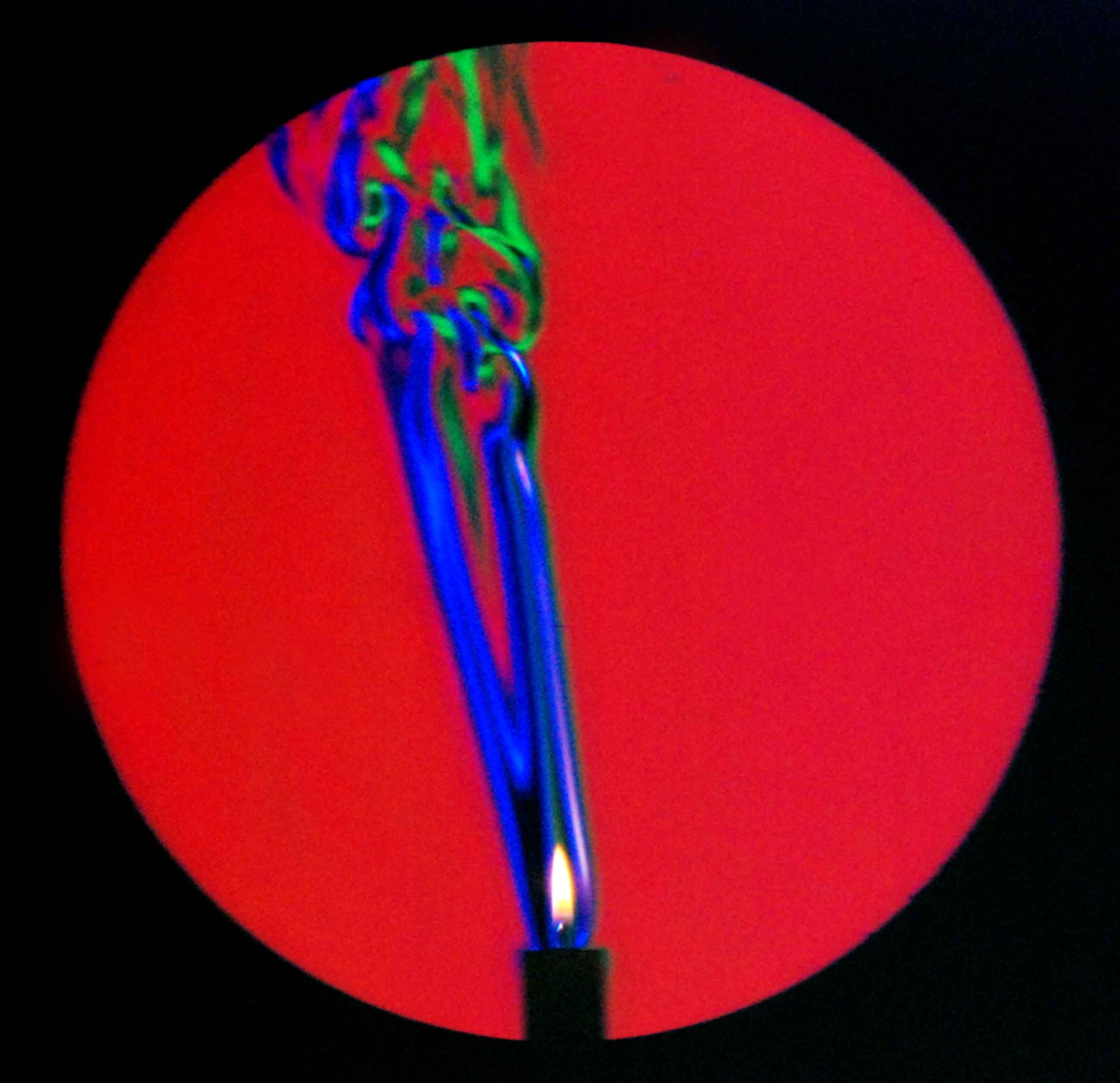
The word “Schlieren” is German, and translates roughly to “streaks”. What is streaky photography, and why might you want to use it in a project? And where did this funny term come from?
Think of the heat shimmer you can see on a hot day. From the ideal gas law, we know that hot air is less dense than cold air. Because of that density difference, it has a slightly lower refractive index. A light ray passing through a density gradient faces a gradient of refractive index, so is bent, hence the shimmer.
Heat shimmer: the refractive index of the air is all over the place. Image: “Livestock crossing the road in Queensland, Australia” by [AlphaLemur]German lens-makers started talking about “Schelieren” sometime in the 19th century, if not before. Put yourself in the shoes of an early lensmaker: you’ve spent countless hours laboriously grinding away at a glass blank until it achieves the perfect curvature. Washing it clean of grit, you hold it to the light and you see aberration — maybe spatial, maybe chromatic. Schliere is the least colourful word you might say, but a schliere is at fault. Any wonder lens makers started to develop techniques to detect the invisible flaws they called schlieren?
When we talk of schlieren imagery today, we generally aren’t talking about inspecting glass blanks. Most of the time, we’re talking about a family of fluid-visualization techniques. We owe that nomenclature to German physicist August Toepler, who applied these optical techniques to visualizing fluid flow in the middle of the 19th century. There is now a whole family of schlieren imaging techniques, but at the core, they all rely on one simple fact: in a fluid like air, refractive index varies by density.
Toepler’s pioneering setup is the one we usually see in hacks nowadays. It is based on the Foucault Knife Edge Test for telescope mirrors. In Foucault’s test, a point source shines upon a concave mirror, and a razor blade is placed where the rays focus down to a point. The sensor, or Foucault’s eye, is behind the knife edge such that the returning light from the pinhole is interrupted. This has the effect of magnifying any flaws in the lens, because rays that deviate from the perfect return path will be blocked by the knife-edge and miss the eye.
[Toepler]’s single-mirror layout is quick and easy.Toepler’s photographic setup worked the same way, save for the replacement of the eye with a photographic camera, and the use of a known-good mirror. Any density changes in the air will refract the returning rays, and cause the characteristic light and dark patterns of a schlieren photograph. That’s the “classic” schlieren we’ve covered before, but it’s not the only game in town.
Fun Schlieren Tricks
A little color can make a big difference for any kind of visualization. (Image: “Colored schlieren image“ by [Settles1])For example, a small tweak that makes a big aesthetic difference is to replace the knife edge with a colour filter. The refracted rays then take on the colour of the filter. Indeed, with a couple of colour filters you can colour-code density variations: light that passes through high-density areas can be diverted through two different colored filters on either side, and the unbent rays can pass through a third. Not only is it very pretty, the human eye has an easier time picking up on variations in colour than value. Alternatively, the light from the point source can be passed through a prism. The linear spread of the frequencies from the prism has a similar effect to a line of colour filters: distortion gets color-coded.
A bigger tweak uses two convex mirrors, in two-mirror or Z-path schlieren. This has two main advantages: one, the parallel rays between the mirrors mean the test area can be behind glass, useful for keeping sensitive optics outside of a high-speed wind tunnel. (This is the technique NASA used to use.) Parallel rays also ensure that the shadow of both any objects and the fluid flow are no issue; having the light source off-centre in the classic schrilien can cause artifacts from shadows. Of course you pay for these advantages: literally, in the sense that you have to buy two mirrors, and figuratively in that alignment is twice as tricky. The same colour tricks work just as well, though, and was in often use at NASA.
The z-fold allows for parallel rays in the test area.
There’s absolutely no reason that you could not substitute lenses for mirrors, in either the Z-path or classical version, and people have to good effect in both cases. Indeed, Robert Hooke’s first experiment involved visualizing the flow of air above a candle using a converging lens, which was optically equivalent to Toepler’s classic single-mirror setup. Generally speaking, mirrors are preferred for the same reason you never see an 8” refracting telescope at a star party: big mirrors are way easier to make than large lenses.
T-34s captured in flight with NASA’s AirBOS technique. Image credit : NASA.
What if you want to visualize something that doesn’t fit in front of a mirror? There are actually several options. One is background-oriented schrilien, which we’ve covered here. With a known background, deviations from it can be extracted using digital signal processing techniques. We showed it working with a smart phone and a printed page, but you can use any non-uniform background. NASA uses the ground: by looking down, Airborn Background Oriented Schlieren (AirBOS) can provide flow visualization of shockwaves and vortices around an airplane in flight.
In the days before we all had supercomputers in our pockets, large-scale flow-visualization was still possible; it just needed an optical trick. A pair of matching grids is needed: one before the lamp, creating a projection of light and dark, and a second one before the lens. Rays deflected by density variations will run into the camera grid. This was used to good effect by Gary S. Styles to visualize HVAC airflows in 1997
Can’t find a big mirror? Try a grid.
Which gets us to another application, separate from aerospace. Wind tunnel photos are very cool, but let’s be honest: most of us are not working on supersonic drones or rocket nozzles. Of course air flow does not have to be supersonic to create density variations; subsonic wind tunnels can be equipped with schlieren optics as well.
HVAC as you’ve never seen it before. Imagine those were ABS fumes? (Image from Styles, 1997.)
Or maybe you are more concerned with airflow around components? To ID a hotspot on a board, IR photography is much easier. On the other hand, if your hotspot is due to insufficient cooling rather than component failure? Schlieren imagery can help you visualize the flow of air around the board, letting you optimize the cooling paths.
That’s probably going to be easiest with the background-oriented version: you can just stick the background on one side of your project’s enclosure and go to work. I think that if any of you start using schlieren imaging in your projects, this might be the killer app that will inspire you to do so.
Another place we use air? In the maker space. I have yet to see someone use schlieren photography to tweak the cooling ducts on their 3D printer, but you certainly could. (It has been used to see shielding gasses in welding, for example.) For that matter, depending what you print, proper exhaust of the fumes is a major health concern. Those fumes will show up easily, given the temperature difference, and possibly even the chemical composition changing the density of the air.
Remember that the key thing being imaged isn’t temperature difference, but density difference. Sound waves are density waves, can they be imaged in this way? Yes! The standing waves in ultrasonic levitation rigs are a popular target. Stroboscopic effects can be used for non-standing waves, though keep in mind that the sound pressure level is the inverse of frequency, so audible frequencies may not be practical if you like your eardrums.
Schlieren photography isn’t limited to air. Density variations in liquids and solids are game, too. Want to see how multiple solutions of varying density or tempeature are mixing? Schlieren imaging has you covered. Watch convection in a water tank? Or, if you happen to be making lenses, you could go right back to basics and use one of the schlieren techniques discussed here to help you make them perfect.
The real reason I’m writing about these techniques aren’t the varied applications I hope you hackers can put them to: it’s an excuse to collect all the pretty pictures of flow visualization I can cram into this article. So if you read this and thought “I have no practical reason to use this technique, but it does seem cool” – great! We’re in the same boat. Let’s make some pretty pictures. It still counts as a hack.
The iMac G3 is an absolute icon of industrial design, as (or perhaps more) era-defining than the Mac Classic before it. In the modern day, if your old iMac even boots, well, you can’t do much with it. [Rick Norcross] got a hold of a dead (hopefully irreparable) specimen, and stuffed a modern PC inside of it.
From the outside, it’s suprizingly hard to tell. Of course the CRT had to go, replaced with a 15″ ELO panel that fits well after being de-bezeled. (If its resolution is only 1024 x 768, well, it’s also only 15″, and that pixel density matches the case.) An M-ATX motherboard squeezes right in, above a modular PSU. Cooling comes from a 140 mm case fan placed under the original handle. Of course you can’t have an old Mac without a startup chime, and [Rick] obliges by including an Adafruit FX board wired to the internal speakers, set to chime on power-up while the PC components are booting.
These sorts of mods have proven controversial in the past– certainly there’s good reason to want to preserve aging hardware–but perhaps with this generation of iMac it won’t raise the same ire as when someone guts a Mac Classic. We’ve seen the same treatment given to a G4 iMac, but somehow the lamp doesn’t quite have the same place in our hearts as the redoubtable jellybean.
They might call it Levity, but there’s nothing funny about Rapid Liquid Print’s new silicone 3D printer. It has to be seen to be believed, and luckily [3D Printing Nerd] gives us lots of beauty shots in this short video, embedded below.
Smooth, and fast. This bladder took 51 minutes according to the RLP website.
Printing a liquid, even a somewhat-viscous one like platinum-cure silicone, presents certain obvious challenges. The Levity solves them with buoyancy: the prints are deposited not onto a bed, but into a gel, meaning they are fully supported as the silicone cures. The fact that the liquid doesn’t cure instantly has a side benefit: the layers bleed into one another, which means this technique should (in theory) be much more isotropic in strength than FDM printing. We have no data to back that up, but what you can see for yourself that the layer-blending creates a very smooth appearance in the finished prints.
If you watch the video, it really looks like magic, the way prints appear in the gel. The gel is apparently a commercially-available hydrogel, which is good since the build volume looks to need ̶a̶b̶o̶u̶t̶ ̶5̶0̶0̶ ̶L̶ at least 125 L of the stuff. The two-part silicone is also industry-standard and off-the-shelf, though no doubt the exact ratios and are tweaked for purpose. There’s no magic, just a really neat technology.
If you want one, you can sign up for the waiting list at Rapid Liquid Print’s website, but be prepared to wait; units ship next year, and there’s already a list.
Alternatively, since there is no magic here, we’d love to see someone take it on themselves, the way once equally exotic SLS printers have entered the DIY world. There was a time when resin printers were new and exotic and hobbyists had to roll their own, too. None of this is to say we don’t respect the dickens out of the Rapid Liquid Print team and their achievement–it’s just that imitation is the sincerest form of flattery.