During this year’s Hackaday Supercon, the Supplyframe DesignLab will be playing host to a unique exhibit that catalogs the evolution of display technology. That means showcasing the best and most interesting examples they can find, from the vintage to the ultra-modern. Where are all these wonderful toys coming from, you might ask? Why, the Hackaday community, of course.
This is a rare chance to show off your prized gadgetry to a captive audience of hackers and makers. Whether it’s a custom display you’ve created or some gonzo piece of hardware you’ve been holding onto for years, now’s the time to haul it out. However, there are only a few days left to submit your display for potential inclusion, so if you’ve got something you want the Hackaday community to see, make sure you fill out the form before the September 16th deadline. That’s Monday, if you were wondering.
The folks at the DesignLab tell us they’ve already got some very cool pieces of hardware lined up, many of which readers will recognize from these pages. We’re eager to get up close and personal with some of these incredible creations we’ve covered over the years, and we’re willing to bet many of the Supercon attendees will, too.
While we don’t want to give away too much, here’s a quick look at a couple of the displays currently slated for exhibition:
The More the Merrier
While there are some truly gorgeous examples lined up for the November exhibit, there are still a few gaps in the collection we’d love to see addressed. If you’ve got any of the following that you’d like to show off, please don’t hesitate to get in touch:
Unique LCDs (I.E. Tiger handhelds)
Vintage Displays
CRTs (All Types)
Plasma Displays
Nixie Clocks/Displays
Anything Custom Built
Video Synthesizers
For some of those, like CRTs, submissions would ideally come from the Southern California area. But in general, submissions from all over the globe are welcome.
If you’ve been holding off on submitting because you’re worried somebody else has sent in for the same thing, don’t be. Showing different permutations of a particular display technology is a bit part of the exhibit — we’d rather have too many Nixie clocks to choose from than not enough.
IO user [monte] was pointed towards an 1898 display patent issued to a [George Mason] and liked the look of the ‘creepy’ font it defined. The layout used no less than 21 discrete segments to display the complete roman alphabet and numerals, which is definitely not possible with the mere seven segments we are all familiar with. [monte] then did the decent thing and created a demonstration digit using modern parts.
For the implementation, [monte] created a simple PCB by hand (with an obvious mistake) and 3D-printed an enclosure and diffuser to match. After a little debugging, a better PCB was ordered from one of the usual overseas factories. There isn’t a schematic yet, but they mention using a CH32V003 Risc-V micro, which can be seen sitting on the rear of the PCB.
Maximum flexibility is ensured by storing every glyph as a 32-bit integer, with each LED corresponding to a single bit. It’s interesting to note the display incorporates serifs, which are definitely optional, although you could display sans-serif style glyphs if you wanted to. There is now a bit of a job to work out how to map character codes to glyph codes, but you can have a go at that yourself here. It’s still early doors on this project, but it has some real potential for a unique-looking display.
All of the usual tiny superlatives and comparisons apply to [Chronova Engineering]’s latest effort — fits on a pencil eraser, don’t sneeze while you’re working on it or you’ll never find it. If we were to put the footprint of this engine into SMD context, we’d say it’s around a 2010 or so. As one would expect, the design is minimalistic, with no room for traditional bearings or valves. The piston and connecting rod are one piece, meaning the cylinder must pivot, which provides a clever way of switching between intake and exhaust. Tiny crankshaft, tiny flywheel. Everything you’d associate with a steam engine is there, but just barely.
The tooling needed to accomplish this feat is pretty impressive too. [Chronova] are no strangers to precision work, but this is a step beyond. Almost everything was done on a watchmaker’s lathe with a milling attachment and a microscope assist. For the main body of the engine, a pantograph engraving machine was enlisted to scale a 3D printed template down tenfold. Drill bits in the 0.3 mm range didn’t fare too well against annealed tool steel, which is where the scanning electron microscope came into play. It revealed brittle fractures in the carbide tool, which prompted a dive down the rabbit hole of micro-machining and a switch to high-speed steel tooling.
It all worked in the end, enough so that the engine managed 42,000 RPM on a test with compressed air. We eagerly await the equally tiny boiler for a live steam test.
While it’s the ideal choice for mass production, injection molding is simply no good for prototyping. The molds are expensive and time-consuming make, so unless you’ve got the funding to burn tens of thousands of dollars on producing new ones each time you make a tweak to your design, they’re the kind of thing you don’t want to have made until you’re absolutely sure everything is dialed in and ready. So how do you get to that point without breaking the bank?
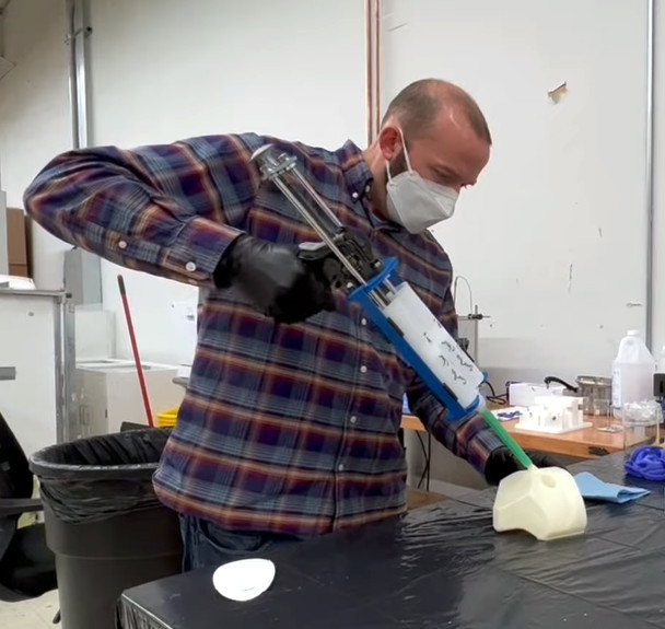
That’s not always an easy question, but if you’re working with silicone parts, the team at OpenAeros thinks they might have a solution for you. As demonstrated through their OpenRespirator project, the team has developed a method of 3D printing single-use molds suitable for large silicone parts that they’re calling Digital-to-Silicone (D2S).
In the video below, [Aaron] and [Jon] explain that they started off by simply printing injection molds in the traditional style. This worked, but the molds can get quite complex, and the time and effort necessary to design and print them wasn’t a great fit for their iterative development cycle. They wanted to be able to do from design to prototype in a day, not a week.
Eventually they realized that if they printed the mold out of a water-soluble filament, they could simplify its design greatly. They’ve documented the design process in detail, but the short version is that you essentially subtract the 3D model of the design you want to produce from a solid shape in your CAD package, and add a few holes for injecting the silicone. Once the silicone has cured, the mold can be dissolved away in warm water to reveal the finished part.
They then took this concept a step further. Thanks to the multi-material capabilities offered by some of the latest 3D printers, it’s possible to print structures within the mold. Once the silicone is injected, these structures can become part of the finished part. For the OpenRespirator, this lets them add PETG stiffening rings around where the filters to snap into the silicone mask body.
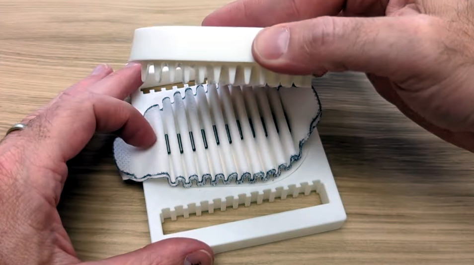
As an added bonus, the video also goes over their method of prototyping pleated filters with 3D printed forms. After inserting the filter media, snap-in arms push it down into the valleys of the form to create the pleats. These are held in place with the addition of small metal rods that are attracted to the magnets embedded into the form. Once the top and bottom of the form have been closed over the filter, silicone is injected to create a ring around the filter and lock everything into place.
We often think of 3D printing as ideal for prototyping, but usually in a very direct and obvious way. You print out a part to see if it works the way you want, and then take the design and have it made out of something stronger. But this presentation from OpenAeros shows just how versatile the technology can be. With even a half-way decent desktop printer, the potential time and cost savings can be enormous. Something to keep in mind should one of your side projects turn into something bigger.
The bulbs inside scanners (before transitioning to LED, anyway) were cold cathode fluorescent tubes that emit a fairly wide bandwidth of light. They were purpose-built to produce a very specific type and shape of light, but [Julius Curt] has taken this in a new, upcycled direction. Instead of just producing light, the light itself is also part of the aesthetic. A very cool 3D printed case houses the bulb and power supply and smartly hides the connecting wires to achieve a very clean look.
Part of the design involves adding a DC-DC converter before the lamp driver, allowing fading of the light. This isn’t anything new in lamps, but [Julius] noticed an interesting effect when dimming the vertically oriented lamp: as the power was reduced, the column of light would start to extinguish from one end, leading to an elongated teardrop-shaped light source.
This leads to a very interesting look, and the neat case design leads to an extremely unique lamp! The emitted light’s color temperature seems to vary a bit as the voltage drops, going from what appears to be a pretty cold white to a slightly warmer tone.
The design process is detailed on the project page, with a quick look at the CAD design process for the case. A neat touch was using a greeble (part of a coffee grinder) to add some different textures and break up the plastic-only look. That’s one we’ll have to note in our design books!
Beyond the power variant, it sometimes seems as though we rarely encounter a discrete transistor these days, such has been the advance of integrated electronics. But they have a rich history, going back through the silicon era to germanium junction transistors, and thence to the original devices. if you’ve ever looked at the symbol for a transistor and wondered what it represents, it’s a picture of those earliest transistors, which were point contact devices. A piece of germanium as the base had two metal electrodes touching it as the emitter or collector, and as [Marcin Marciniak] shows us, you can make one yourself (Polish language, Google Translate link).
These home made transistors sacrifice a point contact diode to get the small chip of germanium, and form the other two electrodes with metal foil glued to paper. Given that germanium point contact diodes are themselves a rarity these days we’re guessing that some of you will be wincing at that. The video below is in Polish so you’ll have to enable YouTube’s translation if you’re an Anglophone — but we understand that the contact has to be made by passing a current through it, and is then secured with a drop of beeswax.
A slight surprise comes in how point contact transistors are used, unlike today’s devices their gain in common emitter mode was so poor that they took instead a common base configuration. There’s a picture of a project using three of them, a very period radio receiver with bulky transformers between all stages.
Usually, when you need to sense something in a project, the answers are straightforward. Want to sense air temperature? There’s a sensor for that. Particulate content in the air? There’s a sensor for that, too. Someone sneaking up on you? Get yourself some passive infrared sensors (PIRs) and maybe a smart camera just to be sure.
But sometimes you can be sneaky instead, saving the cost of a sensor by using alternative techniques. Perhaps there’s a way to use the hardware you already have to determine what you need. Maybe you can use statistical methods to calculate the quantity you’re looking for from other measurements.
Today, we’ll examine a great example of a “pseudo-sensor” build in an existing commercial device, and examine how these techniques are often put to good use in industry.
Case Study
When they were introduced in 2009, Coca-Cola Freestyle dispensers were a step change in the way soft drinks were dispensed. Suddenly, you weren’t limited to five or six choices on the soda fountain. You could instead sample virtually the entire Coca Cola range, all on one machine! If you’re a big soda head, this was a very rad thing. If you were a maintenance tech for Coca Cola, though, you probably saw the machine differently — not as some godly fount of soda, but as a machine to be troubleshooted, repaired, and improved. Over time, it became obvious that the Freestyle unit had a high rate of Flow Control Module (FCM) replacements in the field. And yet, 50% of the FCMs returned to Coca Cola weren’t faulty. There was something strange going on.
The problem, as revealed in a presentation from the company, was that the Freestyle machine didn’t have a dedicated pressure sensor in the fluid line. If a machine had an FCM fault or a pressure loss, it would present much the same way. Thus, techs would often swap out a perfectly good FCM when the problem was actually elsewhere. The solution was obvious: there needed to be a way to sense pressure in the system, so techs could determine if an FCM was faulty or if the problem was a lack of pressure upstream.
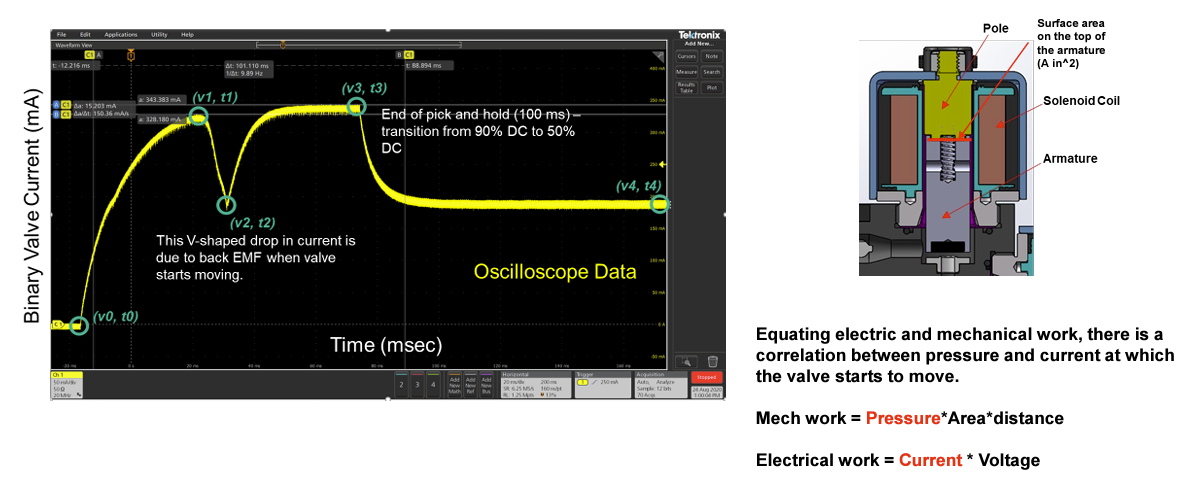
There’s a characteristic dip in the current flowing to the FCM valve when it opens—and it change with pressure.
To address this, an engineer might have specified an off-the-shelf pressure sensor, figured out how to retrofit it to the machine, and rolled them out in the wild. Instead, Coca-Cola developed an innovative (and presumably cheaper) solution: a pressure pseudo-sensor, largely using equipment already on the machine.
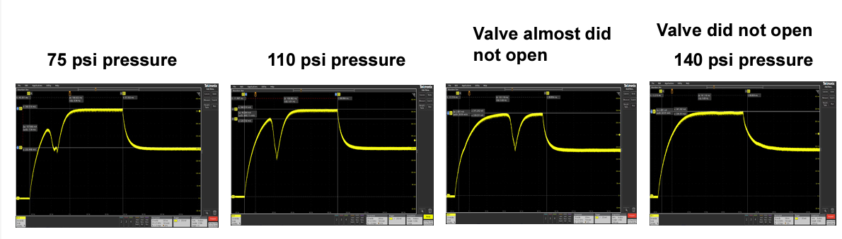
The pseudo pressure sensor operates by analyzing the relationship between electrical and mechanical work within the FCM. Basically, the FCM is a valve that opens to allow the flow of fluid through the machine. Thus, the pseudo-sensor monitors the current at which the valve starts to move, a value that correlates with the pressure inside the system. As pressure increases, a characteristic V-shaped drop in current is observed; this pattern shifts as pressure changes, allowing the system to estimate the pressure based on the observed current.
A complicated function ties pressure to the features of the FCM current curve.
To create the pseudo-sensor, a whole lot of data was collected from the Freestyle hardware. Over 5,000 drink pours were performed with a number of FCM modules, at pressures from 1 to 140 pounds per square inch (PSI) at 5 PSI intervals. The data collected during testing was then fed into MATLAB and Simulink in order to create a mathematical model. The aim was to link the peak size of the current feedback voltage dip measured by the current sensor, and link that to pressure. Sadly, a good reliable correlation was hard to come by.
More work ensued, which tied pressure to multiple timing and voltage features on the curve. These were fed into a multi-variable regression that spat out a monstrous model that calculated pressure from six features and 26 terms. It was messy, but far more accurate, and it did the job.
From there, it was a simple matter of deploying the model that measured FCM current and spat our pressure measurements. It was loaded on an ARM Cortex M microcontroller and put through 3,300 tests over 10 different FCMs and two different Freestyle controller boards. The model predicted the correct pressure within a bound of +/- 10 PSI a full 85% of the time.
Admittedly, that would be rubbish for a proper pressure sensor. However, for a simple pseudo-sensor that’s mostly just used to see if there’s pressure in the system? It’s pretty darn good. The pseudo-sensor software has since been deployed on Freestyle machines in the field, with work ongoing to further develop the system’s diagnostics using this new tool.
The pseudo-sensor actually does a pretty good job!
Other Examples
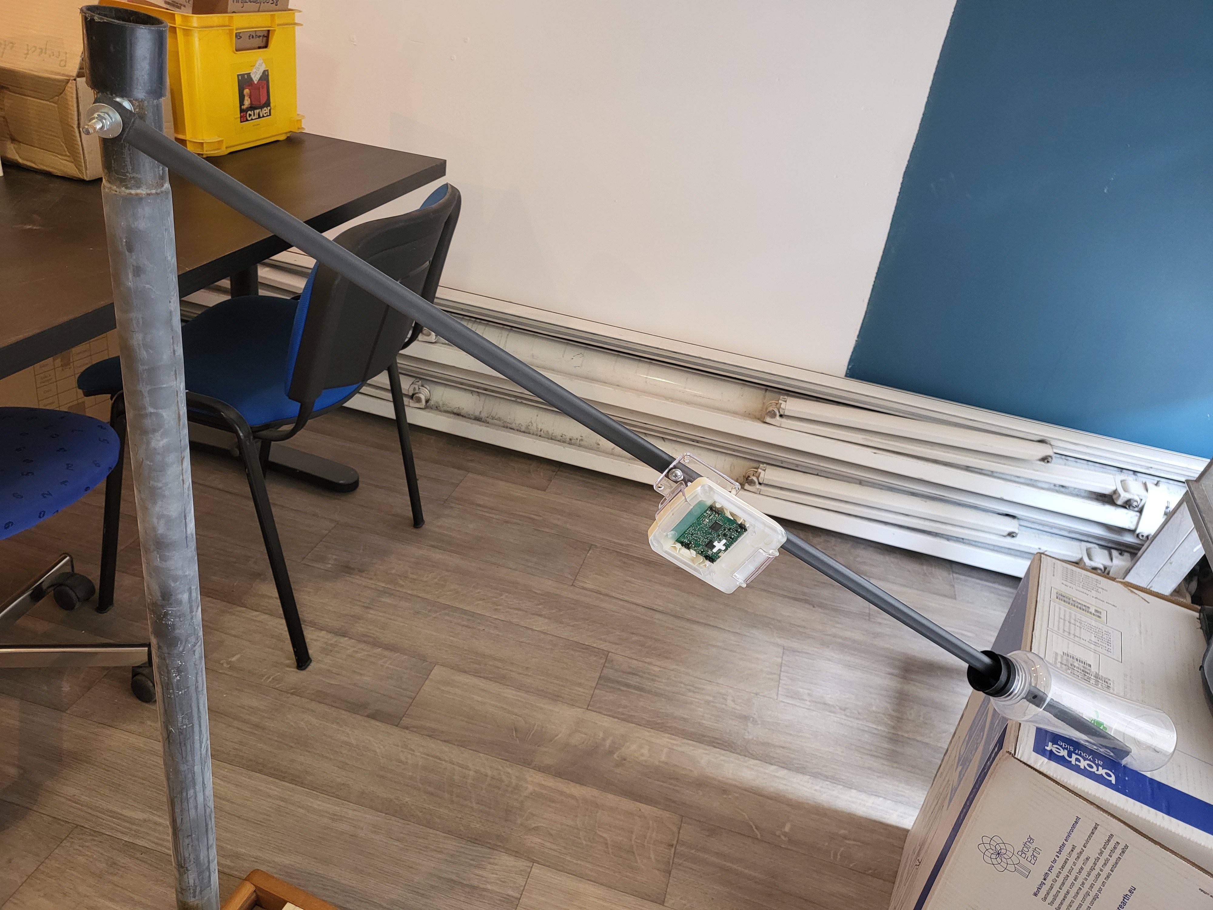
The simple fact is that you can often get by with indirect measurement techniques if you’re constrained by things like cost, complexity, or practicality. We’ve seen other work along these very lines before. Back in 2022, we covered the work of Brian Wyld, who wanted to measure the level of a body of water. Pressure and direct surface-level sensors were impractical, so he got creative. He built a rotating arm with a float on one side, and threw on a microcontroller board with an accelerometer included. The accelerometer readings were enough to allow him to figure out the angle of the float, and in turn, mathematically derive the water level as desired via simple geometry!
“We need to measure the water level but we only have an accelerometer!” “No problem.” Credit: Brian Wyld
We’ve also seen how this can go wrong. For example, capacitive sensors are often suggested for measuring soil moisture levels. The idea is that by measuring the capacitance of the soil, you can measure how much water content there is. The only problem is that moisture isn’t the only thing that changes the capacitance of the soil.
For these indirect techniques to work well, what you’re measuring needs to have a fairly direct correlation with what you’re trying to find out. Hence why Wyld’s float was a success — because the float angle is directly relevant to the water level. Similarly, in Coca-Cola’s case, pressure was what determined the change in the current curve of the Freestyle FCM. If the curve also changed significantly with ambient temperature or some other factor, it wouldn’t be possible to measure it and get out a reliable pressure value.
Ultimately, pseudo-sensors can be a useful tool to have in your engineering toolkit. They can let you achieve surprising feats with some mathematical insight and basic equipment. Just make sure there’s a strong basis for what you’re doing so you don’t end up with junk outputs that cause you more harm than good.
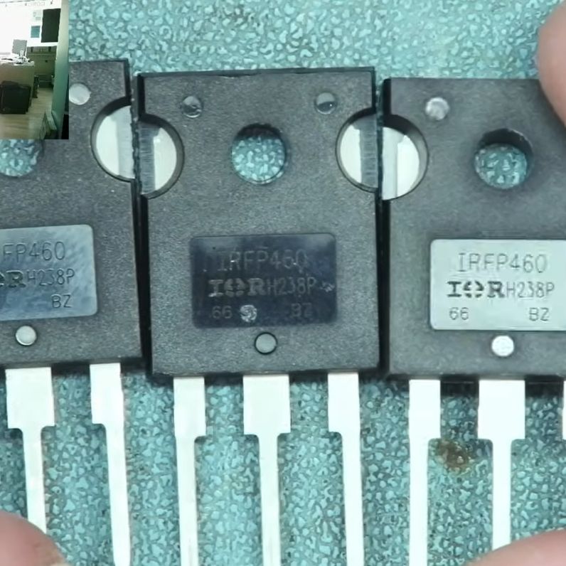
The fake AliExpress-sourced IRFP460 MOSFETs (Credit: Learn Electronics Repair, YouTube)
These days, it’s super-easy to jump onto the World Wide Web to find purported replacement parts using nothing but the part identifier, whether it’s from a reputable source like Digikey or Mouser or from more general digital fleamarkets like eBay and AliExpress. It’s hardly a secret that many of the parts you can buy online via fleamarkets are not genuine. That is, the printed details on the package do not match the actual die inside. After AliExpress-sourced MOSFETs blew in a power supply repair by [Learn Electronics Repair], he first tried to give the MOSFETs the benefit of the doubt. Using an incandescent lightbulb as a current limiter, he analyzed the entire PSU circuit before putting the blame on the MOSFETs (IRFP460) and ordering new ones from LCSC.
Buying from a distributor instead of a marketplace means you can be sure the parts are from the manufacturer. This means that when a part says it is a MOSFET with specific parameters, it almost certainly is. A quick component tester session showed the gate threshold of the LCSC-sourced MOSFETs to be around 3.36V, while that of the AliExpress ‘IRFP460’ parts was a hair above 1.8V, giving a solid clue that whatever is inside the AliExpress-sourced MOSFETs is not what the package says it should be.
Unsurprisingly, after fitting the PSU with the two LCSC-sourced MOSFETs, there was no more magic smoke, and the PSU now works. The lesson here is to be careful buying parts of unknown provenance unless you like magic smoke and chasing weird bugs.
NEMA-17 steppers are (almost) a dime a dozen. They’re everywhere, they’re well-known to hackers and makers, and yet they’re still a bit hard to integrate into projects. That’s because the motor alone isn’t much use, and by the time you find or build a driver and integrate it with a microcontroller, you’ve probably expended more effort than you will on the rest of the project. This USB-C PD stepper driver aims to change that.
What caught our eye about [Josh Rogan]’s PD Stepper is his effort to make this a product rather than just a project. The driver is based on a TMC2209 for silent operation and a lot of torque thanks to the power delivery capabilities of USB-C PD. The PCB is very nicely designed and has an AS5600 rotary magnetic encoder for closed-loop operation. There’s also an ESP32-S3 on-board, so WiFi and Bluetooth operation are possible — perfect for integration into Home Assistant via ESPHome.
[Josh]’s mechanical design is top-notch, too, with a machined aluminum spacer that fits on the back of a NEMA-17 motor perfectly and acts as a heat spreader. A machined polycarbonate cover protects the PCB and makes a very neat presentation. [Josh] has kits available, or you can roll your own with the provided build files.
The new Raspberry Pi Pico 2 with its RP2350 microcontroller has only been with us for a short time, and thus its capabilities are still being tested. One of the new peripherals is HSTX, for which the description “High speed serial port” does not adequately describe how far it is from the humble UART which the name might suggest. CNX Software have taken a look at its capabilities, and it’s worth a read.
With a 150 MHz clock and 8 available pins, it’s a serial output with a combined bandwidth of 2400 Mbps, which immediately leaves all manner of potential for streamed outputs. On the RP2040 for example a DVI output was made using the PIO peripherals, while here the example code shows how to use these pins instead. We’re guessing it will be exploited for all manner of pseudo-analogue awesomeness in the manner we’re used to with the I2S peripherals on the EP32. Of course, there’s no corresponding input, but that still leaves plenty of potential.