These days everything needs to be connected to remote servers via the internet, whether it’s one’s TV, fridge or even that new car you just bought. A recently discovered (and already patched) vulnerability concerning Kia cars was a doozy in this regard, as a fairly straightforward series of steps allowed for any attacker to obtain the vehicle identification number (VIN) from the license plate, and from there become registered as the car’s owner on Kia’s network. The hack and the way it was discovered is described in great detail on [Sam Curry]’s website, along with the timeline of its discovery.
Notable is that this isn’t the first vulnerability discovered in Kia’s HTTP-based APIs, with [Sam] this time taking a poke at the dealer endpoints. To his surprise, he was able to register as a dealer and obtain a valid session ID using which he could then proceed to query Kia’s systems for a user’s registered email address and phone number.
With a specially crafted tool to automate the entire process, this information was then used to demote the car’s owner and register the attacker as the primary owner. After this the attacker was free to lock/unlock the doors, honk to his heart’s content, locate the car and start/stop the vehicle. The vulnerability affected all Kia cars made after 2013, with the victim having no indication of their vehicle having been hijacked in this manner. Aside from the doors randomly locking, the quaint honking and engine turning on/off at a whim, of course.
Perhaps the scariest part about this kind of vulnerability is that it could have allowed an attacker to identify a vulnerable parked car, gained access, before getting into the car, starting the engine and driving away. As long as these remote APIs allow for such levels of control, one might hope that one day car manufacturers will take security somewhat more serious, as this is only the latest in a seemingly endless series of amusingly terrifying security vulnerabilities that require nothing more than some bored hackers with HTTP query crafting tools to discover.
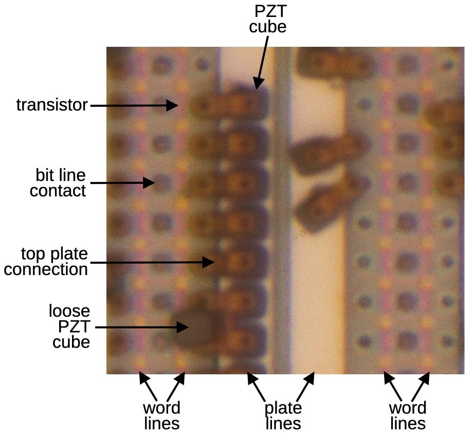
Structure of the Ramtron FeRAM. The image is focus-stacked for clarity. (Credit: Ken Shirriff)
Although not as prevalent as Flash memory storage, ferroelectric RAM (FeRAM) offers a range of benefits over the former, mostly in terms of endurance and durability, which makes it popular for a range of (niche) applications. Recently [Ken Shirriff] had a look inside a Ramtron FM24C64 FeRAM IC from 1999, to get an idea of how it works. The full die photo can be seen above, and it can store a total of 64 kilobit.
One way to think of FeRAM is as a very small version of magnetic core memory, with lead-zirconate-titanate (PZT) ferroelectric elements making up the individual bits. These PZT elements are used as ferroelectric capacitors, i.e. the ferroelectric material is the dielectric between the two plates, with a positive voltage storing a ‘1’, and vice-versa.
In this particular FeRAM chip, there are two capacitors per bit, which makes it easier to distinguish the polarization state and thus the stored value. Since the distinction between a 0 and a 1 is relatively minor, the sense amplifiers are required to boost the signal. After a read action, the stored value will have been destroyed, necessitating a write-after-read action to restore the value, all of which adds to the required logic to manage the FeRAM. Together with the complexity of integrating these PZT elements into the circuitry this makes these chips relatively hard to produce and scale down.
You can purchase FeRAM off-the-shelf and research is ongoing, but it looks to remain a cool niche technology barring any kind of major breakthrough. That said, the Sega Sonic the Hedgehog 3 cartridges which used an FeRAM chip for save data are probably quite indestructible due to this technology.
Long before the advent of the Internet and the World Wide Web, there were other ways to go online, with Ohio-based CompuServe being the first to offer a consumer-oriented service on September 24, 1979. In an article by [Michael De Bonis] a listener-submitted question to WOSU’s Curious Cbus is answered, interspersed with recollections of former users of the service. So what was CompuServe’s contribution to society that was so important that the state of Ohio gave historical status to the building that once housed this company?
The history of CompuServe and the consumer-facing services which it would develop started in 1969, when it was a timesharing and remote access service for businesses who wanted to buy some time on the PDP-10s that Golden United Life Insurance as the company’s subsidiary used. CompuServe divested in 1975 to become its own, NASDAQ-listed company. As noted in the article, while selling timeshares to businesses went well, after business hours they would have these big computer systems sitting mostly idly. This was developed by 1979 into a plan to give consumers with their newfangled microcomputers like the TRS-80 access.
Originally called MicroNet and marketed by Radio Shack, the service offered the CompuServe menu to users when they logged in, giving access to features like email, weather, stock quotes, online shipping and booking of airline tickets, as well as online forums and interactive text games.
Later renamed to CompuServe Information Service (CIS), it remained competitive with competitors like AOL and Prodigy until the mid-90s, even buying one competitor called The Source. Ultimately it was the rise of Internet and the WWW that would close the door on this chapter of computing history, even as for CompuServe users this new Internet age would have felt very familiar, indeed.
Everyone knows that time’s arrow only goes in one direction, regardless of the system or material involved. In the case of material time, i.e. the ageing of materials such as amorphous materials resulting from glass transition, this material time is determined after the initial solidification by the relaxation of localized stresses and medium-scale reordering. These changes are induced by the out-of-equilibrium state of the amorphous material, and result in changes to the material’s properties, such as a change from ductile to a brittle state in metallic glasses. It is this material time which the authors of a recent paper (preprint) in Nature Physics postulates to be reversible.
Whether or not this is possible is said to be dependent on the stationarity of the stochastic processes involved in the physical ageing. Determining this stationarity through the investigation of the material time in a number of metallic glass materials (1-phenyl-1-propanol, laponite and polymerizing epoxy) was the goal of this investigation by [Till Böhmer] and colleagues, and found that at least in these three materials to be the case, suggesting that this process is in fact reversible.
Naturally, the primary use of this research is to validate theories regarding the ageing of materials, other aspects of which have been investigated over the years, such as the atomic dynamics by [V.M Giordano] and colleagues in a 2016 paper in Nature Communications, and a 2022 study by [Birte Riechers] and colleagues in Science Advances on predicting the nonlinear physical ageing process of glasses.
While none of these studies will give us time-travel powers, it does give us a better understanding of how materials age over time, including biological systems like our bodies. This would definitely seem to be a cause worthy of our time.
On 11 March, 2011, a massive magnitude 9.1 earthquake shook the west coast of Japan, with the epicenter located at a shallow depth of 32 km, a mere 72 km off the coast of Oshika Peninsula, of the Touhoku region. Following this earthquake, an equally massive tsunami made its way towards Japan’s eastern shores, flooding many kilometers inland. Over 20,000 people were killed by the tsunami and earthquake, thousands of whom were dragged into the ocean when the tsunami retreated. This Touhoku earthquake was the most devastating in Japan’s history, both in human and economic cost, but also in the effect it had on one of Japan’s nuclear power plants: the six-unit Fukushima Daiichi plant.
In the subsequent Investigation Commission report by the Japanese Diet, a lack of safety culture at the plant’s owner (TEPCO) was noted, along with significant corruption and poor emergency preparation, all of which resulted in the preventable meltdown of three of the plant’s reactors and a botched evacuation. Although afterwards TEPCO was nationalized, and a new nuclear regulatory body established, this still left Japan with the daunting task of cleaning up the damaged Fukushima Daiichi nuclear plant.
Removal of the damaged fuel rods is the biggest priority, as this will take care of the main radiation hazard. This year TEPCO has begun work on removing the damaged fuel inside the cores, the outcome of which will set the pace for the rest of the clean-up.
Safety Cheese Holes
Overview of a GE reactor as at Fukushima Daiichi. (Credit: WNA)
The Fukushima Daiichi nuclear power plant was built between 1967 and 1979, with the first unit coming online in 1970 and the third unit by 1975. It features three generations of General Electric-designed boiling water reactors of a 1960s (Generation II) design. It features what is known as a Mark I containment structure. At the time of the earthquake only units 1, 2 and 3 were active, with the quake triggering safeties which shut down these reactors as designed. The quake itself did not cause significant damage to the reactors, but three TEPCO employees at the Fukushima Daiichi and Daini plants died as a result of the earthquake.
A mere 41 minutes later the first tsunami hit, followed by a second tsunami 8 minutes later, leading to the events of the Fukushima Daiichi accident. The too low seawall did not contain the tsunami, allowing water to submerge the land behind it. This damaged the seawater pumps for the main and auxiliary condenser circuits, while also flooding the turbine hall basements containing the emergency diesel generators and electrical switching gear. The backup batteries for units 1 and 2 also got taken out in the flooding, disabling instrumentation, control and lighting.
One hour after the emergency shutdown of units 1 through 3, they were still producing about 1.5% of their nominal thermal power. With no way to shed the heat externally, the hot steam, and eventually hydrogen from hot steam interacting with the zirconium-alloy fuel rod cladding, was diverted into the dry primary containment and then the wetwell, with the Emergency Core Cooling System (ECCS) injecting replacement water. This kept the cores mostly intact over the course of three days, with seawater eventually injected externally, though the fuel rods would eventually melt due to dropping core water levels, before solidifying inside the reactor pressure vessel (RPV) as well as on the concrete below it.
It was attempted to vent the steam pressure in unit 1, but this resulted in the hydrogen-rich air to flow into the service floor, where it found an ignition source and blew off the roof. To prevent this with unit 2, a blow-out panel was opened, but unit 3 suffered a similar hydrogen explosion on the service floor, with part of the hydrogen also making it into the defueled unit 4 via ducts and similarly blowing off its roof.
The hydrogen issue was later resolved by injecting nitrogen into the RPVs of units 1 through 3, along with external cooling and power being supplied to the reactors. This stabilized the three crippled reactors to the point where clean-up could be considered after the decay of the short-lived isotopes present in the released air. These isotopes consisted of mostly iodine-131, with a half-life of 8 days, but also cesium-137, with a half-life of 30 years, and a number of other isotopes.
Nuclear Pick-up Sticks
Before the hydrogen explosions ripped out the service floors and the building roofs, the clean-up would probably have been significantly easier. Now it seemed that the first tasks would consist out of service floor clean-up of tangled metal and creating temporary roofs to keep the elements out and any radioactive particles inside. These roof covers are fitted with cameras as well as radiation and hydrogen sensors. They also provide the means for a crane to remove fuel rods from the spent fuel pools at the top of the reactors, as most of the original cranes were destroyed in the hydrogen explosions.
Phot of the damaged unit 1 of Fukushima Daiichi and a schematic overview of the status. (Credit: TEPCO)
This meant that the next task is to remove all spent fuel from these spent fuel pools, with the status being tracked on the TEPCO status page. As units 5 and 6 were undamaged, they are not part of these clean-up efforts and will be retained after clean-up and decommissioning of units 1-4 for training purposes.
Meanwhile, spent fuel rods were removed already from units 3 and 4. For unit 1, a cover still has to be constructed as has has been done for unit 3, while for the more intact unit 2 a fuel handling facility is being constructed on the side of the building. Currently a lot of the hang-up with unit 1 is the removal of debris on the service floor, without risking disturbing the debris too much, like a gigantic game of pick-up sticks. Within a few years, these last spent fuel rods can then be safely transported off-site for storage, reprocessing and the manufacturing of fresh reactor fuel. That’s projected to be 2026 for Unit 2 and 2028 for Unit 1.
This spent fuel removal stage will be followed by removing the remnants of the fuel rods from inside the RPVs, which is the trickiest part as the normal way to defuel these three boiling-water reactors was rendered impossible due to the hydrogen explosions and the melting of fuel rods into puddles of corium mostly outside of the RPVs. The mostly intact unit number 2 is the first target of this stage of the clean-up.
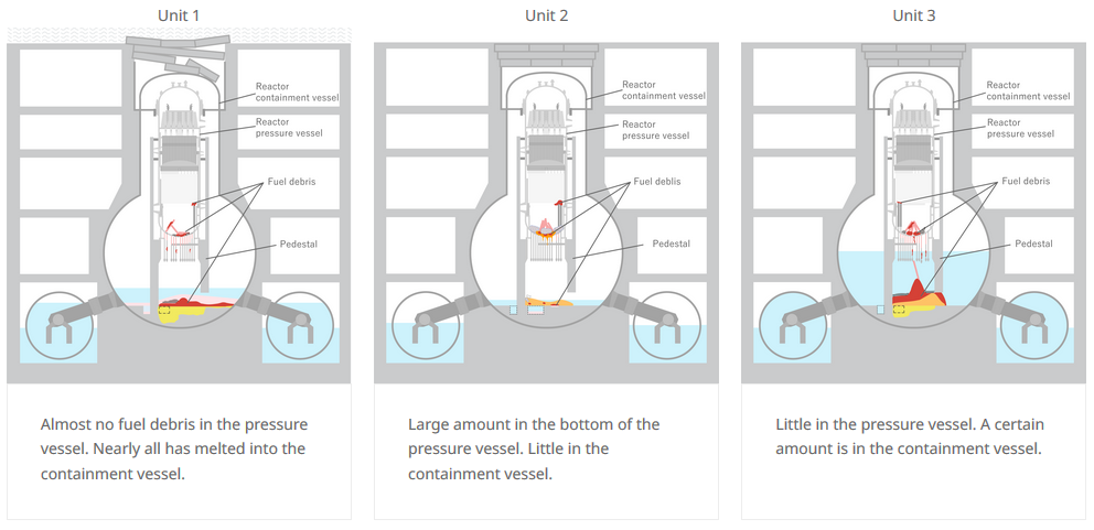
Estimated corium distribution in Fukushima Daiichi unit 1 through 3. (Credit: TEPCO)
To develop an appropriate approach, TEPCO relies heavily on exploration using robotic systems. These can explore the insides of the units, even in areas which are deemed unsafe for humans and can be made to fit into narrow tubes and vents to explore even the insides of the RPVs. This is how we have some idea of where the corium ended up, allowing for a plan to be formed for the extracting of this corium for disposal.
Detailed updates on the progress of the clean-up can be found as monthly reports, which also provide updates on any changes noted inside the damaged units. Currently the cores are completely stable, but there is the ongoing issue of ground- and rainwater making it into the buildings, which causes radioactive particles to be carried along into the soil. This is why groundwater at the site has been for years now been pumped up and treated with the ALPS radioactive isotope removal system. This leaves just water with some tritium, which after mixing with seawater is released into the ocean. The effective tritium release this way is lower than when the Fukushima Daiichi plant was operating.
TEPCO employees connect pipes that push the ‘Telesco’ robot into the containment of Unit 2 for core sample retrieval. (Credit: TEPCO)
In these reports we also get updates on the robotic exploration, but the most recent update here involves a telescoping robot nicknamed ‘Telesco’ (because it can extend by 22 meters) which is tasked with retrieving a corium sample of a few grams from the unit 2 reactor, in the area underneath the RPV where significant amounts of corium have collected. This can then be analyzed and any findings factored into the next steps, which would involve removing the tons of corium. This debris consists of the ceramic uranium fuel, the zirconium-alloy cladding, the RPV steel and the transuranics and minor actinides like plutonium, Cs-137 and Sr-90, making it radiologically quite ‘hot’.
Looking Ahead
Although the clean-up of Fukushima Daiichi may seem slow, with a projected completion date decades from now, the fact of the matter is that time is in our favor, as the issue of radiological contamination lessens with every passing day. Although the groundwater contamination is probably the issue that gets the most attention, courtesy of the highly visible storage tanks, this is now fully contained including with sea walls, and there is even an argument to be made that dilution of radioisotopes into the ocean would make it a non-issue.
Regardless of the current debate about radiological overreacting and safe background levels, most of the exclusion zone around the Fukushima Daiichi plant has already been reopened, with only some zones still marked as ‘problematic’, despite having background radiation levels that are no higher than the natural levels in other inhabited regions of the world. This is also the finding of the UNSCEAR in their 2020 status report (PDF), which finds levels of Cs-137 in marine foods having dropped already sharply by 2015, no radiation-related events in those evacuated or workers in the exclusion zone, and no observed effects on the local fauna and flora.
Along with the rather extreme top soil remediation measures that continue in the exclusion zone, it seems likely that within a few years this exclusion zone will be mostly lifted, and the stricken plant itself devoid of spent fuel rods, even as the gradual removal of the corium will have begun. First starting with small samples, then larger pieces, until all that will left inside units 1-3 will be some radioactive dust, clearing the way to demolish the buildings. But it’s a long road.
Although less popular these days, wire-wrap is still a very relevant, easily reversible solder-free way to assemble (prototype) systems using wire-wrap wire and a wire-wrap tool. This latter tool can be either a hand or powered tool, but all it has to do is retain the stripped wire, fit around the wire-wrapping post and create a snug, oxidation-proof metal-metal contact fit. For the very common 30 AWG (0.25 mm) wire-wrap wire, the Jonard Tools (OK Industries) WSU-30M wire-strip-unwrap tool is pretty much the popular standard. It allows you to strip off insulation, wrap and unwrap connections all with one tool, but the question is whether you can just 3D print a wrap-unwrap tool that’s about as good?
First a note about cost, as although the genuine WSU-30M has risen in cost over the years, it can still be obtained for around $50 from retails like Mouser, while clones of varying quality can be obtained for around $15 from your favorite e-tailer website. From experience, these clones have quite sloppy tolerance, and provide a baseline of where a wrapping tool becomes unusable, as they require some modding to be reliable.
Wire-wrap tool model by [KidSwidden] on Thingiverse.Taking a quick look at the wire-wrap tools available on Thingiverrse, we can see basically two categories: one which goes for minimally viable, with just a cylinder that has a hole poked on the side for the stripped wire to fit through, as these versions by [JLSA_Portfolio], [paulgeneres], [orionids] and [cmellano]. The WSU-30M and similar tools have a channel on the side that the stripped wire is fed into, to prevent it from getting tangled up and snagging. On the clone units this channel often has to be taped off to prevent the wire from escaping and demonstrating why retaining the wire prior to wrapping is a good idea.
This leads us to three examples of a 3D printed wire-wrap tool with such a wire channel: by [KidSwidden] (based on a Radio Shack unit, apparently), another by [DieKatzchen] and an interesting variation by [4sStylZ]. Naturally, the problem with such fine features is that tolerance matter a lot, with an 0.2 mm nozzle (for FDM printers) recommended, and the use of an SLA printer probably a good idea. It’s also hard to say what kind of wire-wrap connection you are going to get, as there are actually two variants: regular and modified.
The starting guide to wire-wrapping by Sparkfun uses the WSU-30M, which as the name suggests uses modified wire-wrap, which means that part of the wire insulation is wrapped around the bottom of the post, for extra mechanical stability, effectively like strain-relief. A lot of such essential details are covered in this [Nuts and Volts] article which provides an invaluable starting guide to wire-wrapping, including detecting bad wraps.
Naturally, the 3D printed tools will not include a stripper for the wire insulation, so you will have to provide this yourself (PSA: using your teeth is not recommended), and none of these 3D models include an unwrap tool, which may or may not be an issue for you, as careful unwrapping allows you to reuse the wire, which can be useful while debugging or reworking a board.
Top image: completed wire-wrap on a post. (Credit: Sparkfun)
Raw network sockets are a curious beasts, as unless you have a strong urge to implement your own low-level network protocol, it’s a topic that is probably best left to the (well-paid) experts. That said, you can totally use raw sockets in virtually every operating system, but one should be aware of a few things, the lack of portability being one of them. This is what tripped [Swagnik] up while trying to write a low-level network ping (ICMP) utility, by reading the Linux socket documentation while testing on MacOS. It’s all BSD-style sockets, after all, right?
As it turns out, the network stacks in Linux and MacOS have some subtle differences, which become apparent when you read the friendly manuals. For Linux, the raw(7) man entry for IPv4 sockets make it clear that the IP_HDRINCL socket option is default by default for IPPROTO_RAW sockets. This is different from MacOS, which is effectively FreeBSD with glossy makeup. Like FreeBSD, the MacOS man page makes it clear that the IP_HDRINCL option is not set by default.
So that’s easy, right? Just fire off a setsockopt() call on the raw socket and that’s done. Not quite. The Linux man page notes that it cannot receive all IP protocols, while the FreeBSD/MacOS version makes no such exceptions. There is also the issue of endianness, which is where [Swagnik]’s blog post seems to err. The claim is that on MacOS the received IPv4 raw socket header is in host (little endian) order, while the documentation clearly notes that these are in network (big endian) order, which the blog post also shows.
Where things get really fun is when moving from IPv4 raw sockets to IPv6 raw sockets, as [Michael F. Schönitzer] covered for Linux back in 2018 already. IPv6 raw sockets drop IP_HDRINCL and requires a whole different approach. The endianness also changes, as IPv6 raw sockets under Linux must send and will receive data in network byte order, putting it in line with FreeBSD raw sockets.
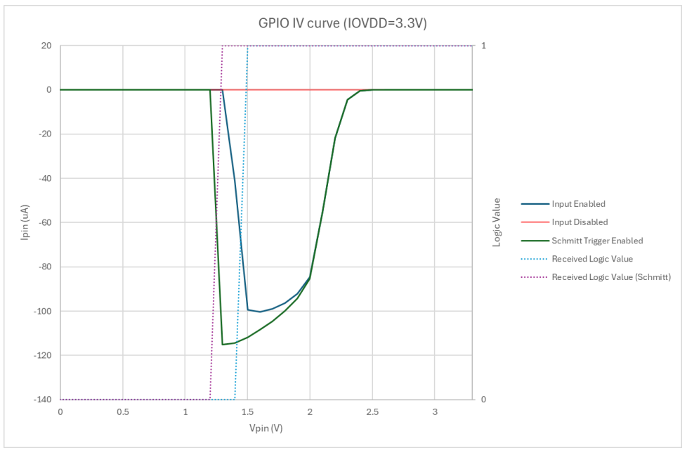
Although initially defined as an issue with GPIO inputs when configured with the internal pull-downs enabled, erratum RP2350-E9 has recently been redefined in the datasheet (page 1341) as a case of increased leakage current. As it is now understood since we previously reported, the issue occurs when a GPIO (0 – 47) is configured as input, the input buffer is enabled, and the pad voltage is somewhere between logic LOW and HIGH. In that case leakage current can be as high as 120 µA with IOVDD = 3.3 V. This leakage current is too much for the internal pull-up to overcome, ergo the need for an external pull-down: 8.2 kΩ or less, per the erratum. Disabling the input buffer will stop the leakage current, but reading the input requires re-enabling the buffer.
GPIO Pad leakage for IOVDD=3.3 V (Credit: Raspberry Pi)
The upshot of this issue is that for input applications, the internal pull-downs are useless, and since PIO applications cannot toggle pad controls, the input buffer toggling workaround is not an option. ADC usage requires one to clear the GPIO input enable. In general any circuit that relies on floating pins or an internal pull-down resistor will be affected.
Although this should mean that the affected A2 stepping of the RP2350 MCU can still be used for applications where this is not an issue, and external pull-downs can be used as a ‘fix’ at the cost of extra power usage, it makes what should have been a drop-in replacement a troubled chip at best. At this point there have still been no definite statements from Raspberry Pi regarding a new (B0) stepping, leaving RP MCU users with the choice between the less flashy RP2040 and the buggy RP2350 for the foreseeable future.
Recently, the EPA and COBB Tuning have settled after the latter was sued for providing emissions control defeating equipment. As per the EPA’s settlement details document, COBB Tuning have since 2015 provided customers with the means to disable certain emission controls in cars, in addition to selling aftermarket exhaust pipes with insufficient catalytic systems. As part of the settlement, COBB Tuning will have to destroy any remaining device, delete any such features from its custom tuning software and otherwise take measures to fully comply with the Clean Air Act, in addition to paying a $2,914,000 civil fine.
The tuning of cars has come a long way from the 1960s when tweaking the carburetor air-fuel ratios was the way to get more power. These days cars not only have multiple layers of computers and sensor systems that constantly monitor and tweak the car’s systems, they also have a myriad of emission controls, ranging from permissible air-fuel ratios to catalytic converters. It’s little surprise that these systems can significantly impact the raw performance one might extract from a car’s engine, but if the exhaust of nitrogen-oxides and other pollutants is to be kept within legal limits, simply deleting these limits is not a permissible option.
COBB Tuning proclaimed that they weren’t aware of these issues, and that they never marketed these features as ’emission controls defeating’. They were however aware of issues regarding their products, which is why they announced ‘Project Green Speed’ in 2022, which supposedly would have brought COBB into compliance. Now it would seem that the EPA did find fault despite this, and COBB was forced to making adjustments.
Although perhaps not as egregious as modifying diesel trucks to ‘roll coal’, federal law has made it abundantly clear that if you really want to have fun tweaking and tuning your car without pesky environmental laws getting in the way, you could consider switching to electric drivetrains, even if they’re mind-numbingly easy to make performant compared to internal combustion engines.
Images that can be interpreted in a variety of ways have existed for many decades, with the classical example being Rubin’s vase — which some viewers see as a vase, and others a pair of human faces.
When the duck becomes a bunny, if you ignore the graphical glitches that used to be part of the duck. (Credit: Steve Mould, YouTube)
Where things get trickier is if you want to create an image that changes into something else that looks realistic when you rotate each section of it within a 3×3 grid. In a video by [Steve Mould], he explains how this can be accomplished, by using a diffusion model to identify similar characteristics of two images and to create an output image that effectively contains essential features of both images.
Naturally, this process can be done by hand too, with the goal always being to create a plausible image in either orientation that has enough detail to trick the brain into filling in the details. To head down the path of interpreting what the eye sees as a duck, a bunny, a vase or the outline of faces.
Using a diffusion model to create such illusions is quite a natural fit, as it works with filling in noise until a plausible enough image begins to appear. Of course, whether it is a viable image is ultimately not determined by the model, but by the viewer, as humans are susceptible to such illusions while machine vision still struggles to distinguish a cat from a loaf and a raisin bun from a spotted dog. The imperfections of diffusion models would seem to be a benefit here, as it will happily churn through abstractions and iterations with no understanding or interpretive bias, while the human can steer it towards a viable interpretation.
Although battery fires in electric cars and two-wheeled vehicles are not a common phenomenon, they are notoriously hard to put out, requiring special training and equipment by firefighters. Although the full scope of the issue is part of a contentious debate, [Aarian Marshall] over at Wiredrecently wrote an article about how the electric car industry has a plan to make a purportedly minor issue even less of an issue. Here the questions seem to be mostly about what the true statistics are for battery fires and what can be done about the primary issue with batteries: thermal runaway.
While the Wired article references a study by a car insurance company about the incidence of car fires by fuel type (gas, hybrid, electric), its cited sources are dubious as the NTSB nor NHTSA collect statistics on these fires. The NFPA does, but this only gets you up to 2018, and they note that the data gathering here is spotty. Better data is found from European sources, which makes clear that battery electric vehicles (BEVs) catch fire less often than gasoline cars at 25 per 100,000 cars sold vs 1529/100k for ICE cars, but when BEVs do burn it’s most often (60%) from thermal runaway, which can be due to factors like a short circuit in a cell, overcharging and high ambient temperatures (including from arson or after-effects of a car crash).
As for the claimed ways to make battery-powered vehicles safer, the Wired article mentions the shift to more stable lithium-ion chemistries like lithium-ion phosphate (LiFePO4, or LFP for short), experimenting with solid-state batteries and easier ways to extinguish a fire and disconnect the BEV’s battery, along with firefighter training. Meanwhile the European Union will require a ‘battery passport’ starting in 2027 which tracks the origin, manufacturing and testing of batteries.
Of the risks with batteries, thermal runaway is probably the least predictable, with a review article by [Mahn-Kien Tran] and colleagues in Processes from 2022 covering our current understanding here, including ways to model and predict the occurrence of thermal runaway to increase safety while e.g. charging a battery. As internal shorts due to wear and/or manufacturing defects can be hard to predict, it is essential to detect thermal runaway before it has a chance to get out of hand.
Beyond electric cars, electric bikes are far more notorious for catching on fire, with these devices in New York City having gained the reputation of burning down apartment buildings, generally while charging. As MIT Technology Review reports, a solution here may have been found in battery swapping stations that are equipped with sensors and fire extinguishing systems, so that delivery drivers and other e-bike users do not have to charge batteries at their apartments while praying that they don’t wake up to thick smoke and a screaming fire alarm.
As battery-powered vehicles and devices become more and more common, it’s clear that even if the risk of fire from these vehicles is small compared to their gasoline-powered brethren, those generally do not catch on fire while parked in one’s garage or hallway. Finding ways to mitigate this risk is therefore more than welcome.
Machines that automate the various tedious tasks that come with being a servant in a cat’s household — like feeding and cleaning Mr. Fluffles’ litter box — are generally a godsend, as they ensure a happy cat and a happy human. That is, unless said litter box-cleaning robot kills said cat. That’s the gruesome topic that [Philip Bloom], also known as the bloke of the One Man Five Cats channel on YouTube, decided to investigate after coming across a report about a certain Amazon-bought unit.
The theory of a self-cleaning litter box: a happy Mr. Fluffles.
Although he was unable to get the (generic & often rebranded) unit off Amazon UK, he did get it via AliExpress for £165 + £80 shipping. Although this version lacks the cute ears of other variants, it’s still effectively the same unit, with the same moving components and mechanism. An initial test with a cat plushie gave the result that can be observed in the above image, where the inner part with the opening will move upwards, regardless of whether a cat is currently poking through said opening. Once the victim is stuck, there is no obvious way to free the trapped critter, which has already led to the death of a number of cats.
The other self-cleaning litter boxes which [Philip] owns have a number of safety features, including a weight sensor, an infrared sensor above the opening to detect nearby critters, a top that will pop off rather than trap a critter, as well as a pinch sensor. During a test with his own hand, [Philip] managed to get injured, and following a banana test, he had a nice banana smoothie.
What takes the cake here is that after [Philip] connected the mobile app for the litter box, he found that there was a firmware update that seems to actually change the machine to use the pinch and infrared sensors that do exist in the litter box, but which clearly were not used properly or at all with the shipped firmware. This means that anyone who buys any of these self-cleaning litter boxes and does not update the firmware runs the significant risk of losing their pet(s) in a gruesome incident. In the video a number of such tragic deaths are covered, which can be rather distressing for any cat lover.
Of note here is that even with the improved firmware, any issue with the sensors will still inevitably lead to the tragic death of Mr. Fluffles. If you do want to obtain a self-cleaning litter box, make sure to for example get one of [Philip]’s recommendations which come with a paw stamp of approval from his own precious fluff balls, rather than a random unit off Amazon or AliExpress.
The ‘Sombrero Potential’ as seen with the Higgs mechanism.
One of the exciting aspects of some fields of physics is that they involve calculating the expected time until the Universe ends or experiences fundamental shifts that would render most if not all of the ‘laws of physics’ invalid. Within the Standard Model (SM), the false vacuum state is one such aspect, as it implies that the Universe’s quantum fields that determine macrolevel effects like mass can shift through quantum field decay into a lower, more stable state. One such field is the Higgs field, which according to a team of researchers may decay sooner than we had previously assumed.
As the Higgs field (through the Higgs boson) is responsible for giving particles mass, it’s not hard to imagine the chaos that would ensue if part of the Higgs field were to decay and cause a spherical ripple effect throughout the Universe. Particle masses would change, along with all associated physics, as suddenly the lower Higgs field state means that everything has significantly more mass. To say that it would shake up the Universe would an understatement.
Of course, this expected time-to-decay has only shifted from 10794 years to 10790 years with the corrections to the previous calculations as provided in the paper by [Pietro Baratella] and colleagues, and they also refer to it as ‘slightly shorter’. A sidenote here is also that the electroweak vacuum’s decay is part of the imperfect SM, which much like the false vacuum hypothesis are part of these models, and not based on clear empirical evidence (yet).
After previously working out a suitable approach to create a period-correct paper tape reader for his tube-based, MC14500B processor-inspired computer, [David Lovett] over at the Usagi Electric farm is back with a video on how he made a working tape reader.
The assembled paper tape reader as seen from the front with tape inserted. (Credit: David Lovett, Usage Electric, YouTube)
The tape reader’s purpose is to feed data into the tube-based computer, which for this computer system with its lack of storage memory means that the instructions are fed into the system directly, with the tape also providing the clock signal with a constant row of holes in the tape.
Starting the tape reader build, [David] opted to mill the structural part out of aluminum, which is where a lot of machining relearning takes place. Ultimately he got the parts machined to the paper design specs, with v-grooves for the photodiodes to fit into and a piece to clamp them down. On top of this is placed a part with holes that line up with the photodiodes.
Another alignment piece is added to hold the tape down on the reader while letting light through onto the tape via a slot. After a test assembly [David] was dismayed that due to tolerance issues he cracked two photodiodes within the v-groove clamp, which was a hard lesson with these expensive (and rare) photodiodes.
Although tolerances were somewhat off, [David] is confident that this aluminum machined reader will work once he has it mounted up. Feeding the tape is a problem that is still to be solved. [David] is looking for ideas and suggestions for a good approach within the limitations that he’s working with. At the video’s end, he mentions learning FreeCAD and 3D printing parts in the future. That would probably not be period-correct in this situation, but might be something he could get away with for some applications within the retrocomputing space.
We covered the first video and the thought process behind picking small (1.8 mm diameter) photodiodes as a period-correct tape hole sensor for a 1950s-era computing system, like the 1950s Bendix G-15 that [David] is currently restoring.
After 47 years it’s little wonder that the hydrazine-powered thrusters of the Voyager 1, used to orient the spacecraft in such a way that its 3.7 meter (12 foot) diameter antenna always points back towards Earth, are getting somewhat clogged up. As a result, the team has now switched back to the thrusters which they originally retired back in 2018. The Voyager spacecraft each have three sets (branches) of thrusters. Two sets were originally intended for attitude propulsion, and one for trajectory correction maneuvers, but since leaving the Solar System many years ago, Voyager 1’s navigational needs have become more basic, allowing all three sets to be used effectively interchangeably.
The first set was used until 2002, when clogging of the fuel tubes was detected with silicon dioxide from an aging rubber diaphragm in the fuel tank. The second set of attitude propulsion thrusters was subsequently used until 2018, until clogging caused the team to switch to the third and final set. It is this last set that is now more clogged then the second set, with the fuel tube opening reduced from about 0.25 mm to 0.035 mm. Unlike a few decades ago, the spacecraft is much colder due energy-conserving methods, complicating the switching of thruster sets. Switching on a cold thruster set could damage it, so it had to be warmed up first with its thruster heaters.
The conundrum was where to temporarily borrow power from, as turning off one of the science instruments might be enough to not have it come back online. Ultimately a main heater was turned off for an hour, allowing the thruster swap to take place and allowing Voyager 1 to breathe a bit more freely for now.
Compared to the recent scare involving Voyager 1 where we thought that its computer systems might have died, this matter probably feels more routine to the team in charge, but with a spacecraft that’s the furthest removed man-made spacecraft in outer space, nothing is ever truly routine.
Sliding in an extra slice of cruise ship to lengthen it. (Credit: Silversea cruises)
The number of people going on cruises keeps rising year over year, with the number passengers carried increasing from just over 3.7 million in 1990 to well over 28 million in 2023. This has meant an increasing demand for more and also much larger cruise ships, which has led to an interesting phenomenon where it has become more economical to chop up an existing cruise ship and put in an extra slice to add many meters to each deck. This makes intuitively sense, as the segment added is fairly ‘dumb’, with no engine room, control systems, but mostly more rooms and cabins.
The current top-of-the-line cruise ship experience is exemplified by the Icon class that’s being constructed for the Royal Caribbean Group. The first in this line is the Icon of the Seas, which is the largest cruise ship in the world with a length of 364.75 meters and a gross tonnage of 248,663. All of this cost €1.86 billion and over two years of construction time, compared to around $80 million and a few months in the drydock. When combined with a scheduled maintenance period in the drydock, this ‘Jumboization’ process can be considered to be a great deal that gives existing cruise ships a new lease on life.
Extending a ship in this manner is fairly routine as well, with many ships beyond cruise ships seeing the torch before being split. A newly built segment is then slid in place, the metal segments are welded together, wires, tubing and more are spliced together, before the in and outside are ready for a new coat of paint that makes it seem like nothing ever happened to the ship.
Although not the first to try and build a DIY solar-powered remote control airplane, [ProjectAir]’s recent attempt is the most significant one in recent memory. It follows [rctestflight]’s multi-year saga with its v4 revision in 2019, as well as 2022’s rather big one by [Bearospace]. With so many examples to look at, building a solar-powered RC airplane in 2024 should be a snap, surely?
The first handicap was that [ProjectAir] is based in the UK, which means dealing with the famously sunny weather in those regions. The next issue was that the expensive, 20% efficient solar panels are exceedingly fragile, so the hope was that hot-gluing them to the foam of the airplane would keep them safe, even in the case of a crash. During the first test flights they quickly found that although the airplane few fairly well, the moment the sun vanished behind another cloud, the airplane would quite literally fall out of the sky, damaging some cells in the process.
For the final revision, a storage battery was picked, which got charged with an MPPT charger. The airplane itself was changed to be as low-drag as possible, with 60 photovoltaic (PV) cells stuck to its wings. This resulted in the somewhat spindly, swept wing, tail-less pusher design. After debugging a fun issue with EMI from the motor and the navigation module a test flight could be performed, which had the airplane autonomously keep a fixed course. That’s when everything went horribly wrong.
During the subsequent crash investigation, it was found that a total power loss occurred, due to the MPPT charger overcharging the battery, possibly due to a shared ground with the PV cells. Simultaneously, likely due to rushing the testing as bad weather was incoming, the backup battery on the controller was not installed, resulting in the airplane plummeting once primary power ran out. Fortunately, all of these are fixable issues, while providing a learning experience at the cost of an RC airplane and the PV cells that got destroyed in the crash.
Perhaps most importantly, this shows that even if much of building one’s own PV RC airplane in 2024 is just sticking off-the-shelf modules together, there’s no substitute for good engineering, not to mention assembly & pre-flight checklists.
Many have sought the holy grail of making commercial media both readable and copy-proof, especially once everyone began to copy those floppies. One of these attempts to make floppies copy-proof was Softguard’s Superlok. This in-depth look at this copy protection system by [GloriousCow] comes on the heels of a part 1 that covers Formaster’s Copy-Lock. Interestingly, Sierra switched from Copy-Lock to Superlok for their DOS version of games like King’s Quest, following the industry’s quest in search of this holy grail.
The way that Superlok works is that it loads a (hidden) executable called CPC.COM which proceeds to read the 128 byte key that is stored on a special track 6. With this key the game’s executable is decoded and fun can commence. Without a valid ‘Play’ disk containing the special track and CPC.COM executable all one is instead left with is a request by the game to ‘insert your ORIGINAL disk 1’.
Sierra’s King Quest v1.0 for DOS.
As one can see in the Norton Commander screenshot of a Sierra game disk, the hidden file is easily uncovered in any application that supports showing hidden files. However, CPC.COM couldn’t be executed directly; it needs to be executed from a memory buffer and passed the correct stack parameters. Sierra likely put in very little effort when implementing Softguard’s solution in their products, as Superlok supports changing the encryption key offset and other ways to make life hard for crackers.
Sierra was using version 2.3 of Superlok, but Softguard would also make a version 3.0. This is quite similar to 2.x, but has a gotcha in that it reads across the track index for the outer sector. This requires track wrapping to be implemented. Far from this kind of copy protection cracking being a recent thing, there was a thriving market for products that would circumvent these protections, all the way up to Central Point’s Copy II PC Option Board that would man-in-the-middle between the floppy disk drive and the CPU, intercepting data and render those copy protections pointless.
As for the fate of Softguard, by the end of the 1980s many of its customers were tiring of the cat-and-mouse game between crackers and Softguard, along with issues reported by legitimate users. Customers like Infographics Inc. dropped the Superlok protection by 1987 and by 1992 Softguard was out of business.
While plastics are very useful on their own, they can be much stronger when reinforced and mixed with a range of fibers. Not surprisingly, this includes the thermoplastic polymers which are commonly used with FDM 3D printing, such as polylactic acid (PLA) and polyamide (PA, also known as nylon). Although the most well-known fibers used for this purpose are probably glass fiber (GF) and carbon fiber (CF), these come with a range of issues, including their high abrasiveness when printing and potential carcinogenic properties in the case of carbon fiber.
So what other reinforcing fiber options are there? As it turns out, cellulose is one of these, along with basalt. The former has received a lot of attention currently, as the addition of cellulose and similar elements to thermopolymers such as PLA can create so-called biocomposites that create plastics without the brittleness of PLA, while also being made fully out of plant-based materials.
Regardless of the chosen composite, the goal is to enhance the properties of the base polymer matrix with the reinforcement material. Is cellulose the best material here?
Cellulose Nanofibers
Plastic objects created by fused deposition modeling (FDM) 3D printing are quite different from their injection-molding counterparts. In the case of FDM objects, the relatively poor layer adhesion and presence of voids means that 3D-printed PLA parts only have a fraction of the strength of the molded part, while also affecting the way that any fiber reinforcement can be integrated into the plastic. This latter aspect can also be observed with the commonly sold CF-containing FDM filaments, where small fragments of CF are used rather than long strands.
According to a study by Tushar Ambone et al. (2020) as published (PDF) in Polymer Engineering and Science, FDM-printed PLA has a 49% lower tensile strength and 41% lower modulus compared to compression molded PLA samples. The addition of a small amount of sisal-based cellulose nanofiber (CNF) at 1% by weight to the PLA subsequently improved these parameters by 84% and 63% respectively, with X-ray microtomography showing a reduction in voids compared to the plain PLA. Here the addition of CNF appears to significantly improve the crystallization of the PLA with corresponding improvement in its properties.
Fibers Everywhere
Incidentally a related study by Chuanchom Aumnate et al. (2021) as published in Cellulose used locally (India) sourced kenaf cellulose fibers to reinforce PLA, coming to similar results. This meshes well with the findings by Usha Kiran Sanivada et al. (2020) as published in Polymers, who mixed flax and jute fibers into PLA. Although since they used fairly long fibers in compression and injection molded samples a direct comparison with the FDM results in the Aumnate et al. study is somewhat complicated.
Meanwhile the use of basalt fibers (BF) is already quite well-established alongside glass fibers (GF) in insulation, where it replaced asbestos due to the latter’s rather unpleasant reputation. BF has some advantages over GF in composite materials, as per e.g. Li Yan et al. (2020) including better chemical stability and lower moisture absorption rates. As basalt is primarily composed of silicate, this does raise the specter of it being another potential cause of silicosis and related health risks.
With the primary health risk of mineral fibers like asbestos coming from the jagged, respirable fragments that these can create when damaged in some way, this is probably a very pertinent issue to consider before putting certain fibers quite literally everywhere.
A 2018 review by Seung-Hyun Park in Saf Health Work titled “Types and Health Hazards of Fibrous Materials Used as Asbestos Substitutes” provides a good overview of the relative risks of a range of asbestos-replacements, including BF (mineral wool) and cellulose. Here mineral wool fibers got rated as IARC Group 3 (insufficient evidence of carcinogenicity) except for the more biopersistent types (Group 2B, possibly carcinogenic), while cellulose is considered to be completely safe.
Finally, related to cellulose, there is also ongoing research on using lignin (present in plants next to cellulose as cell reinforcement) to improve the properties of PLA in combination with cellulose. An example is found in a 2021 study by Diana Gregor-Svetec et al. as published in Polymers. PLA composites created with lignin and surface-modified nanofibrillated (nanofiber) cellulose (NFC). A 2023 study by Sofia P. Makri et al. (also in Polymers) examined methods to improve the dispersion of the lignin nanoparticles. The benefit of lignin in a PLA/NFC composite appears to be in UV stabilization most of all, which should make objects FDM printed using this material last significantly longer when placed outside.
End Of Life
Another major question with plastic polymers is what happens with them once they inevitably end up discarded in the environment. There should be little doubt about what happens with cellulose and lignin in this case, as every day many tons of cellulose and lignin are happily devoured by countless microorganisms around the globe. This means that the only consideration for cellulose-reinforced plastics in an end-of-life scenario is that of the biodegradability of PLA and other base polymers one might use for the polymer composite.
Today, many PLA products end up discarded in landfills or polluting the environment, where PLA’s biodegradability is consistently shown to be poor, similar to other plastics, as it requires an industrial composting process involving microbial and hydrolytic treatments. Although incinerating PLA is not a terrible option due to its chemical composition, it is perhaps an ironic thought that the PLA in cellulose-reinforced PLA might actually be the most durable component in such a composite.
That said, if PLA is properly recycled or composted, it seems to pose few issues compared to other plastics, and any cellulose components would likely not interfere with the process, unlike CF-reinforced PLA, where incinerating it is probably the easiest option.
Do you print with hybrid or fiber-mixed plastics yet?