Vista Normal

Hay nuevos artículos disponibles. Pincha para refrescar la página.
AnteayerSalida Principal

Eight Artificial Neurons Control Fully Autonomous Toy Truck

24 Julio 2025 at 08:00
A photo of the circuitry along with an oscilloscope

Recently the [Global Science Network] released a video of using an artificial brain to control an RC truck.

The video shows a neural network comprised of eight artificial neurons assembled on breadboards used to control a fully autonomous toy truck. The truck is equipped with four proximity sensors, one front, one front left, one front right, and one rear. The sensor readings from the truck are transmitted to the artificial brain which determines which way to turn and whether to go forward or backward. The inputs to each neuron, the “synapses”, can be excitatory to increase the firing rate or inhibitory to decrease the firing rate. The output commands are then returned wirelessly to the truck via a hacked remote control.

This particular type of neural network is called a Spiking Neural Network (SNN) which uses discrete events, called “spikes”, instead of continuous real-valued activations. In these types of networks when a neuron fires matters as well as the strength of the signal. There are other videos on this channel which go into more depth on these topics.

The name of this experimental vehicle is the GSN SNN 4-8-24-2 Autonomous Vehicle, which is short for: Global Science Network Spiking Neural Network 4 Inputs 8 Neurons 24 Synapses 2 Degrees of Freedom Output. The circuitry on both the vehicle and the breadboards is littered with LEDs which give some insight into how it all functions.

If you’re interested in how neural networks can control behavior you might like to see a digital squid’s behavior shaped by a neural network.

Designing an Open Source Multimeter: the HydraMeter

20 Julio 2025 at 20:00
The Open-Source Multimeter: The HydraMeter

Our hacker [John Duffy] wrote in to let us know about a video he put together to explain the design of his open-source multimeter, the HydraMeter.

If you’re interested in how the circuitry for a voltmeter, ohmmeter, or ammeter might work, this video is a masterclass. In this long and detailed video, [John] walks us through his solutions to various challenges he had while designing his own multimeter. We covered this multimeter last year, and this new video elaborates on the design of the HydraMeter which has been a work in progress for years now.

The basic design feeds voltage, current, and resistance front-ends into an Analog to Digital Converter (ADC), which then feeds into a microcontroller and out to the (detachable) display. You can find the KiCad design files on the GitHub page. There is also a write-up on hackaday.io.

The user interface for the meter is… opinionated, and perhaps not to everyone’s taste. In the video, [John] talks a little bit about why he made the UI work the way that it does, and he noted that adding a rotary range switch is a goal for version 2.0.

The case is 3D printed and [John] had glowing things to say about his Bambu printer. He also had glowing things to say about D-sub connectors, but he did not have glowing things to say about Solid Edge, the CAD software he used to design the case.

Thank you, [John], for putting this video together; it is an excellent resource. We look forward to seeing version 2.0 develop soon!

Project Scribe: Receipts for Life

20 Julio 2025 at 08:00
Project Scribe thermal printer printing out a receipt

Here’s a fun project. Over on their YouTube page [Urban Circles] introduces Project Scribe.

The idea behind this project is that you can print out little life “receipts”. Notes, jokes, thoughts, anecdotes, memories. These little paper mementos have a physical reality that goes beyond their informational content. You can cut them up, organize them, scribble on them, highlight them, stick them on the wall, or in a scrapbook. The whole idea of the project is to help you make easier and better decisions every day by nudging you in the direction of being more mindful of where you’ve been and where you’re going.

The project is well documented on its GitHub page. The heart of the project is a thermal printer. These are the things that print the receipts you get from the store. You may need to conduct some research to find the best thermal paper to use; there are some hints and tips on this topic in the documentation. In addition to the thermal printer is a pretty stand to hold it and an Arduino board to drive it. Firmware for the Arduino is provided which will serve a basic web interface via WiFi.

If you build one, we’d love to hear how it goes. If it doesn’t work out, you can always fall back to using the thermal printer to level up your Dungeons and Dragons game.

Thanks to [Brittany L] for writing in about this one.

Software Defined Retro ROMs

20 Julio 2025 at 02:00
One ROM to rule them all.

Here’s something fun from our hacker [Piers]: Software Defined ROMs.

In this series of three videos, [Piers] runs us through what a software defined ROM is, how to make them, and then how to use them.

As [Piers] explains, one frustration a retro technician will face is a failed ROM chip. In the era he’s interested in, there are basically three relevant kinds of ROM chip, all 24-pin Dual Inline Package (DIP):

  • 2364 ROM chip: 8KB; 1x chip-select line
  • 2332 ROM chip: 4KB; 2x chip-select lines
  • 2316 ROM chip: 2KB; 3x chip-select lines

The chip-select line is how the processor indicates to a particular ROM chip that it should be active. When active, a ROM chip will read the value on the address lines and output the data at that address on the data lines.

With his software defined ROMs [Piers] implements the ROM behavior (converting requests on the address lines to results on the data lines) by using a microcontroller. As his ROM boards are software defined, they are eminently configurable, which means he can support all configurations of all three types of ROM.

[Piers] looks at some old ROM datasheets to get details about timing requirements. His functional requirements are that all three types of ROM can be emulated with a single hardware variant (the same microcontroller) with the same footprint (24-pin DIP), that they be hand-solderable, and cheap. Further technical requirements were that the solutions can all be implemented in software (no FPGA), requiring as few onboard components as possible, that the GPIOs be 5V tolerant, that a fast clock speed be available using the on-chip oscillator, that no more than two PCB layers are required, and that all SMD components are 0603 or larger.

He considered various microcontrollers, including PICO/RP2040/RP2350, ESP32, ATMEGA, PIC, STM32F1, and STM32F4. He really wanted the PICO because they are fast and powerful, but they don’t have 5V tolerant GPIOs, so he settled on the STM32F4 instead. He talks in detail about pin selection, PCB routing, and ROM preprocessing (mangling) for optimal performance. The chip loads its data from flash storage into RAM so it has reliable and deterministic performance characteristics. Provision is made for programming pins so the ROMs can be reprogrammed in-circuit.

When it comes to programming, [Piers] has implemented most things in hand-rolled assembly code. The reason, he says, is that he didn’t want variable implementations depending on the version of compiler used.

Now that you have a universal software defined ROM, all you need is a reliable ROM dumper.

GarageMinder: Automatic Garage Door

19 Julio 2025 at 08:00
A photo of the circuitry in its case

After getting a new car, [Solo Pilot] missed the automatic garage door opening and closing system their old car had. So they set about building their own, called GarageMinder. On the project page you will find a bill of materials, schematics, and some notes about the approach taken in various versions of the software. [Solo Pilot] also made the software available.

The basic hardware centers around a Raspberry Pi Zero W, but there are plans to switch to an ESP32. From the car side of things there are built-in continuous Bluetooth Low Energy (BLE) advertisement broadcasts, which the Raspberry Pi can detect. Building a reliable system on top of these unreliable signals is difficult and you can read about some of the challenges and approaches that were taken during development. This is a work in progress and additional techniques and approaches are going to be trialed in future.

If you’re interested in Bluetooth garage door openers be sure to read about using a Bluetooth headset as a garage door opener for your Android device.

Before Macintosh: The Story of the Apple Lisa

19 Julio 2025 at 02:00
Before Macintosh banner with stylized pixelated picture of one

Film maker [David Greelish] wrote in to let us know about his recent documentary: Before Macintosh: The Apple Lisa.

The documentary covers the life of the Apple Lisa. It starts with the genesis of the Lisa Project at Apple, covering its creation, then its marketing, and finally its cancellation. It then discusses the Apple Lisa after Apple, when it became a collectible. Finally the film examines the legacy of the Apple Lisa, today.

The Apple Lisa was an important step on the journey to graphical user interfaces which was a paradigm that was shifting in the early 1980s, contemporary with the Macintosh and the work at Palo Alto. The mouse. Bitmapped graphics. Friendly error messages. These were the innovations of the day.

Apple began work on the Lisa Project in October 1978 but most of its design goals changed after Steve Jobs and his team visited the Xerox Palo Alto Research Center (PARC) in November 1979. On January 19, 1983, the Apple Lisa computer was released by Apple. Two years later it was re-branded as the “Macintosh XL” and was converted to run the Mac system software. Ultimately, on August 1, 1986, the Macintosh XL (Apple Lisa) was cancelled, so as to not interfere with Macintosh sales.

But the Apple Lisa is not forgotten. These days they are collectibles which you can acquire for a few thousand dollars. They are considered a symbol and harbinger of the very significant shift to the graphical user interface which today is commonplace and perhaps even taken for granted.

There is a fun anecdote in the film about what we know today as OK/Cancel. In fact with the Apple Lisa that was originally Do It/Cancel, but it turned out many people read “Do It” as “dolt”, so during usability testing the users were asking “why is it calling me a dolt!?” Thus “Do It” became “OK”.

If you’re interested in the old Apple Lisa be sure to check out LisaGUI which is a browser-based emulator you can use to see what it used to be like.

PVCSub: A Submarine from the Plumbing Aisle

18 Julio 2025 at 23:00
A photo of a fully assembled PVCSub.

Today in the submersibles department our hacker [Rupin Chheda] wrote in to tell us about their submarine project.

This sub is made from a few lengths of PVC piping of various diameters. There is an inflation system comprised of a solenoid and a pump, and a deflation system, also comprised of a solenoid and a pump. The inflation and deflation systems are used to flood or evacuate the ballast which controls depth. There are three pumps for propulsion and steering, one central pump for propulsion and two side pumps for directional control, allowing for steering through differential thrust. Power and control is external and provided via CAT6 cable.

We have covered various submarine projects here at Hackaday before and it is interesting to compare and contrast the designs. One sub we covered recently was this one made mostly from Lego. There are considerable differences in the approach to buoyancy, propulsion, steering, power, and control. Whereas the PVCSub uses separate ballast inflation and deflation systems the Lego sub uses one system that can be run forward or backward; whereas the PVCSub uses a pump for propulsion the Lego sub uses a magnetically coupled propeller; whereas the PVCSub uses differential thrust for steering the Lego sub uses a small propeller; whereas the PVCSub transmits power through external wires, the Lego sub has an onboard battery; and whereas the PVCSub uses the power wires for control the Lego sub is radio controlled.

Just goes to show that there are many ways to skin this particular kind of cat.

Improve Your KiCad Productivity With These Considered Shortcut Keys

18 Julio 2025 at 05:00
Screenshot of the cheatsheet being developed in Inkscape

[Pat Deegan] from Psychogenic Technologies shows us two KiCad tips to save a million clicks, and he made a video to support it, embedded below.

In the same way that it makes sense for you to learn to touch type if you’re going to be using a computer a lot, it makes sense for you to put some thought and effort into your KiCad keyboard shortcuts keys, too.

In this video [Pat] introduces the keymap that he has come up with for the KiCad programs (schematic capture and PCB layout) and explains the rules of thumb that he used to generate his recommended shortcut keys, being:

  • one handed operation; you should try to make sure that you can operate the keyboard with one hand so your other hand can stay on your mouse
  • proximity follows frequency; if you use it a lot it should be close to hand
  • same purpose, same place; across programs similar functions should share the same key
  • birds of a feather flock together; similar and related functionality kept in proximate clusters
  • typing trounces topography; if you have to use both hands for typing you have to take your hand off the mouse anyway so then it doesn’t really matter where on the keyboard the shortcut key is

You can find importable KiCad keymaps and customizable SVG cheatsheets in the downloads section.

[Pat]’s video includes some other tips and commentary, but for us the big takeaway was the keymaps. He’s also got a course that you can follow along with for free. And if you haven’t been keeping abreast of developments, KiCad is now at version 9, as of February this year.

Building a Stirling Engine Bike

17 Julio 2025 at 20:00
A photo of a Stirling Engine attached to a bike

Over on his YouTube channel [Tom Stanton] shows us how to build a Stirling Engine for a bike.

A Stirling Engine is a heat engine, powered by the expansion and contraction of a working fluid (such as air) which is heated and cooled in a cycle. In the video [Tom] begins by demonstrating the Stirling Engine with some model engines and explains the role of the displacer piston. His target power output for his bike engine is 150 watts (about 0.2 horsepower) which is enough power to cycle at about 15 mph (about 24 km/h). After considering a CPU heatsink as the cooling system he decided on water cooling instead.

[Tom] goes on to 3D print and machine various parts for his bike engine. He uses myriad materials including aluminum and Teflon. He isn’t yet comfortable machining steel, so he had the steel part he needed for handling the hot end of the engine manufactured by a third party.

[Tom] explains that when he started the project he had intended to make a steam engine. But after some preliminary research he discovered that a Stirling Engine was a better choice, particularly they are quieter, more efficient, and safer. After a number of false starts and various adjustments he manages to get his engine to run, which is pretty awesome. Standby for part two to see the bike in action!

We have covered the Stirling Engine here on Hackaday many times before. You might like to read about how to create one with minimal parts or how to make one from expedient materials.

2025 One Hertz Challenge: Ham Radio Foxhunt Transmitter

13 Julio 2025 at 20:00
A hand holding the foxhunt transmitter

[Jim Matthews] submitted their Ham Radio foxhunt transmitter project for the 2025 One Hertz Challenge.

This is a clever Spartan build. In order to create a radio beacon for use in a “fox hunt” [Jim] combined a SR-T300 walkie talkie module with a phototransistor and oscillating LED circuit. The phototransistor and oscillating LED are secured face-to-face inside heat shrink tubing which isolates them from ambient light. When the LED flashes on the phototransistor powers the radio which transmits a tone in the UHF band.

A fox hunt is a game played by radio enthusiasts in which players use radio signals to triangulate and find a hidden beacon. [Jim]’s circuit is the beacon, and when it’s powered by a three volt CR2032 battery, it transmits a strong signal over several hundred yards at 433.5 MHz, within the amateur radio UHF band.

If you’re interested in radio beacons you might like to read about the WSPR beacon.

2025 Hackaday One Hertz Challenge

Jcorp Nomad: ESP32-S3 Offline Media Server in a Thumbdrive

13 Julio 2025 at 11:00
Picture of front and back of thumb drive enclosure

[Jackson Studner] wrote in to let us know about his ESP32-based media server: Jcorp Nomad.

This project uses a ESP32-S3 to create a WiFi hotspot you can connect to from your devices. The hotspot is a captive portal which directs the user to a web-interface comprised of static HTML assets which are in situ with the various media on an attached SD card formatted with a FAT32 file system. The static HTML assets are generated by the media.py Python 3 script when the ESP32 boots.

This project exists because the typical Raspberry Pi media server costs more than an ESP32 does. The ESP32 is smaller too, and demands less power.

According to [Jackson] this ESP32-based solution can support at least four concurrent viewers. The captive portal is implemented with DNS and HTTP services from the ESP32. The firmware is an Arduino project that integrates a bunch of libraries to provide the necessary services. The Jcorp Nomad media template supports Books (in pdf files), Music (in mp3 files), and Movies and Shows (in mp4 files). Also there is a convention for including JPEG files which can represent media in the user-interface.

And the icing on the cake? The project files include STL files so you can 3D print an enclosure. All in all, a very nice hack.

This Homebrew CPU Got Its Start in the 1990s

11 Julio 2025 at 11:00
Photo showing the wire-wrapped version and PCB version of MyCPU side-by-side.

[Sylvain Fortin] recently wrote in to tell us about his Homebrew CPU Project, and the story behind this one is truly remarkable.

He began working on this toy CPU back in 1994, over thirty years ago. After learning about the 74LS181 ALU in college he decided to build his own CPU. He made considerable progress back in the 90s and then shelved the project until the pandemic hit when he picked it back up again and started adding some new features. A little later on, a board house approached him with an offer to cover the production cost if he’d like to redo the wire-wrapped project on a PCB. The resulting KiCad files are in the GitHub repository for anyone who wants to play along at home.

An early prototype on breadboard

The ALU on [Sylvain]’s CPU is a 1-bit ALU which he describes as essentially a selectable gate: OR, XOR, AND, NOT. It requires more clock steps to compute something like an addition, but, he tells us, it’s much more challenging and interesting to manage at the microcode level. On his project page you will find various support software written in C#, such as an op-code assembler and a microcode assembler, among other things.

For debugging [Sylvain] started out with das blinkin LEDs but found them too limiting in short order. He was able to upgrade to a 136 channel Agilent 1670G Benchtop Logic Analyzer which he was fortunate to score for cheap on eBay. You can tell this thing is old from the floppy drive on the front panel but it is rocking 136 channels which is seriously OP.

The PCB version is a great improvement but we were interested in the initial wire-wrapped version too. We asked [Sylvain] for photos of the wire-wrapping and he obliged. There’s just something awesome about a wire-wrapped project, don’t you think? If you’re interested in wire-wrapping check out Wire Wrap 101.

SMD Capacitor Doubles as Cheap SD Card Latch

4 Julio 2025 at 08:00
Using an SMD capacitor as a clip for flash media on a circuit board.

Here’s a clever hack. Simple, elegant, and eminently cost-effective: using an SMD capacitor to hold your flash media in place!

This is a hack that can pretty much be summed up with just the image at the top of the page — a carefully placed SMD capacitor soldered to a routed tab makes for an extremely cost effective locking mechanism for the nearby SD card slot. There’s just enough flexibility to easily move the capacitor when its time to insert or eject your media.

It’s worth noting that the capacitor in this example doesn’t even appear to be electrically connected to anything. But there’s also no reason you couldn’t position one of the capacitors in your existing bill of materials (BOM). This form of mechanical support will be much cheaper than special purpose clips or mounts. Not a big deal for low-volume projects, but if you’re going high-volume this is definitely something to keep in mind.

If you’re just getting started with SMD capacitors then one of the first things to learn is how to solder them. Also, if you’re hoping to salvage them then try to look for newer equipment which is more likely to have SMD components than through-hole. If you’re planning to use your capacitors for… “capacitance” (how quaint), you can start by learning the basics. And if you want to know everything you can learn about the history of capacitors, too.

Thanks to [JohnU] for writing in to let us know about this one. Have your own natty hacks? Let us know on the tipsline!

Back to the Future, 40 Years Old, Looks Like the Past

3 Julio 2025 at 14:00

Great Scott! If my calculations are correct, when this baby hits 88 miles per hour, you’re gonna see some serious shit. — Doc Brown

On this day, forty years ago, July 3rd, 1985 the movie Back to the Future was released. While not as fundamental as Hackers or realistic as Sneakers, this movie worked its way into our pantheon. We thought it would be appropriate to commemorate this element of hacker culture on this day, its forty year anniversary.

If you just never got around to watching it, or if it has been a few decades since you did, then you might not recall that the movie is set in two periods. It opens in 1985 and then goes back to 1955. Most of the movie is set in 1955 with Marty trying to get back to 1985 — “back to the future”. The movie celebrates the advanced technology and fashions of 1985 and is all about how silly the technology and fashions of 1955 are as compared with the advancements of 1985. But now it’s the far future, the year 2025, and we thought we might take a look at some of the technology that was enchanting in 1985 but that turned out to be obsolete in “the future”, forty years on.

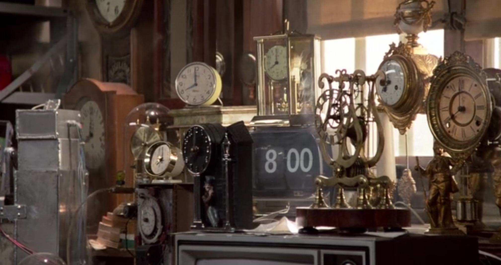
As the opening credits roll there are a bunch of different ticking clocks, signaling the time motif. But they are all analog clocks, some with pendulums, and not an LED or 7-segment display in sight. The only “digital” clock is a split-flap. The signaling of the time motif by clocks is done throughout the film, from the control panel in Doc’s DeLorean time-machine to the stopped clock on the town hall. Of course these days clocks have gotten much better and now they can even set themselves.

We see a wide-angled shot of Doc's vast collection of analog clocks.

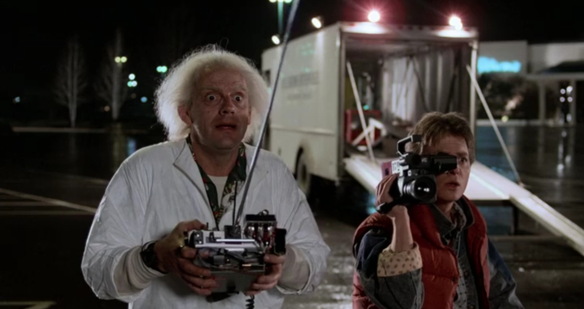
The JVC hand-held video camera recorded to VHS tape. The competing format to VHS at the time was known as Betamax which was developed by Sony. You will of course still find hand-held video cameras today but these days they are far more capable such as with 8K video cameras and you probably have one as a feature of your smartphone anyway. The tape-based VHS and Betamax media has been made obsolete mostly by flash media.

We see Doc controlling the time-machine while Marty records the event with a large video camera; Doc's truck is in the background.

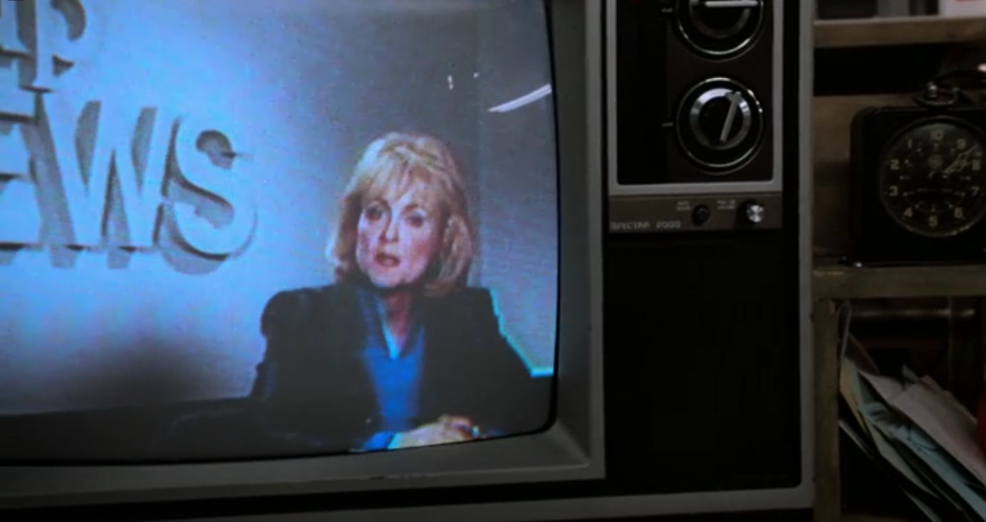
The old Cathode Ray Tube (CRT) television gave way to flat-screen LCD displays and nowadays transparent OLED is state of the art. There were two competing video standards back in 1985 being NTSC which was used in North America, Japan, parts of South America, and so on; and PAL which was used in Europe, Australia, parts of Asia, and Africa.

These old standards didn’t accommodate more than 30 frames-per-second, NTSC was 29.97 Hz and PAL was 25 Hz; and long before “widescreen” 16:9 aspect ratios were released in the 90s they had resolutions of up to 720 × 480 for NTSC and 720 × 576 for PAL. That’s “up to”, there were versions with resolutions worse than this. Of course this is a long way from the 4K@60Hz you have become accustomed to! Also there were no remote controls for these old beasts, you had to get up out of your chair to adjust the volume or change the channel, oh the indignity of it all!

We see an old CRT television with manual dials; a newscaster is presenting the news.

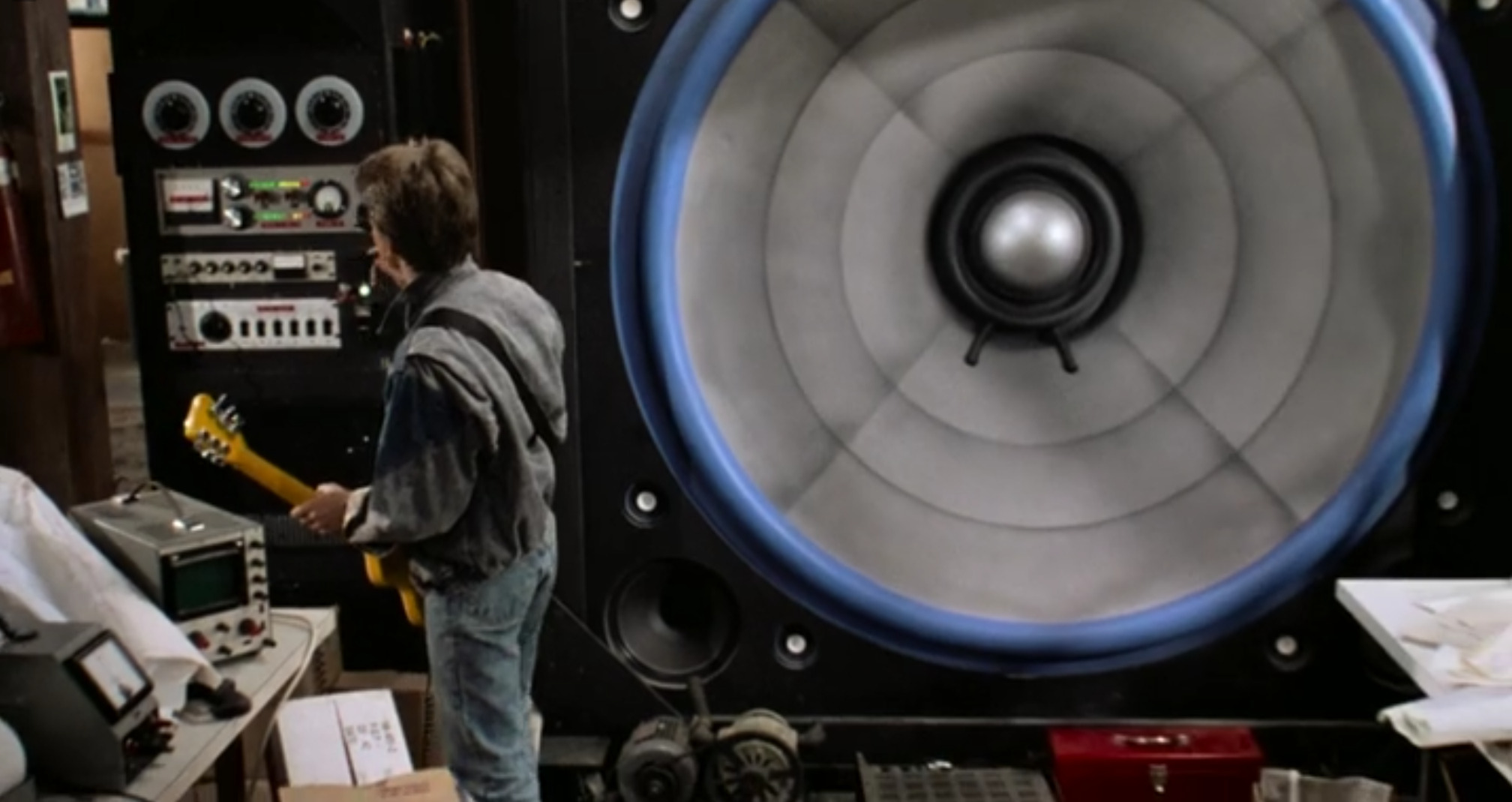
When Marty McFly rocks out, he plugs his guitar into a vacuum tube amplifier, a piece of gear that has proven to have surprisingly long legs. You would think that it would now be an anachronism, replaced by transistor technology, but many guitarists still think that analog vacuum tube technology has a superior and warmer distortion sound. Powering the amp is another dinosaur that survived. The Variac controller shown is an autotransformer that is still made and used, although in 1985 the Variac trademark was owned by General Radio but is now owned by ISE, Inc.

We see the scene widened to include what looks like a CRO and a bench VOM with a red toolbox in the background.
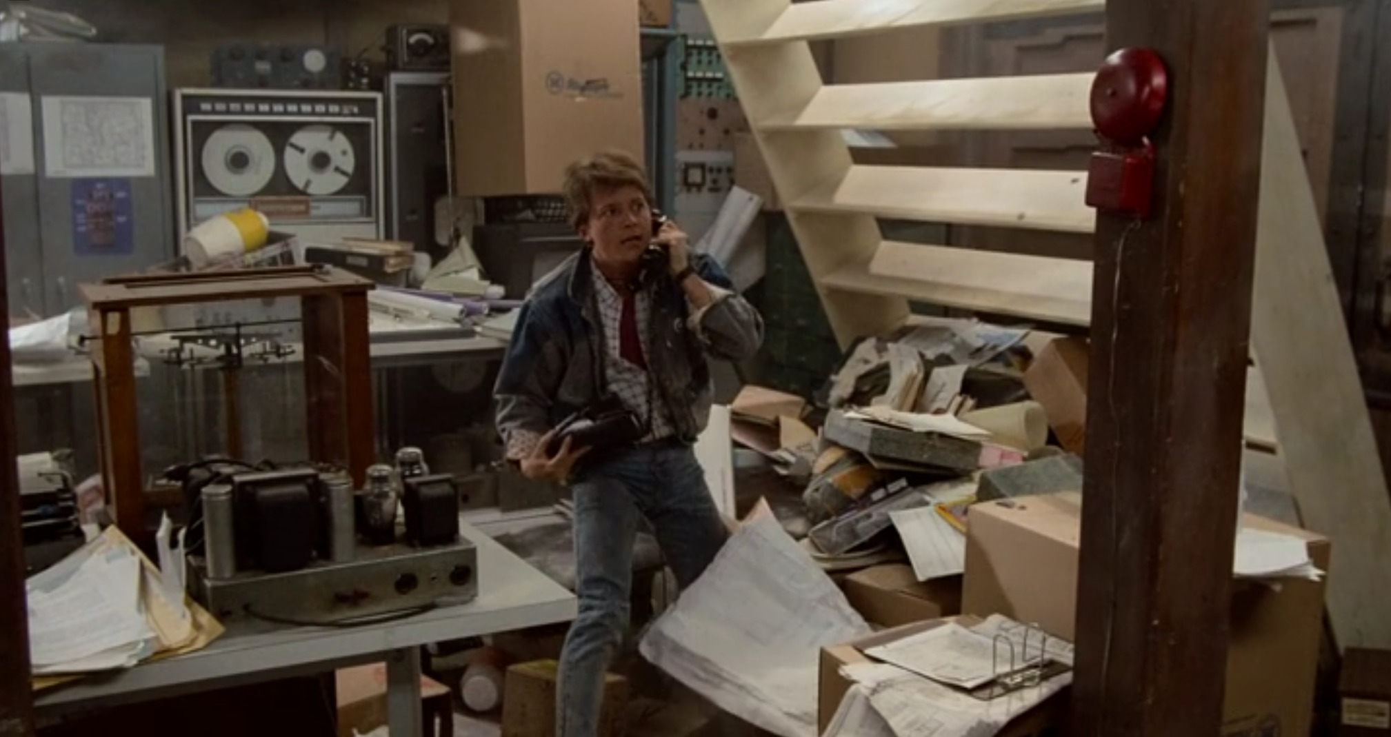
The Cathode-Ray Oscilloscope (CRO) on the table there is completely obsolete, but it remains customary for a hacker to get nostalgic and buy one on eBay. The analog Voltage-Ohm-Milliamp (VOM) meter is maybe only half obsolete, and as with the CRO, a nostalgic hacker will still have one. Everyone else has a Digital Multi-Meter (DMM) which can do everything a VOM could do, and much more.

The old reel-to-reel magnetic tape recorder and player gave way to miniature flash storage in the end. And also a bunch of other media formats in the interim, ranging from floppy-disks to hard-drives. Reel-to-reel magnetic tech had a number of drawbacks, not least was that rewinding and fast-forwarding to find the track you were looking for was a real hassle. (Should we say a reel hassle?) Also the signal would get weaker and more distorted the more copies were made, this was known as generation loss and isn’t relevant to digital media.

We see Marty on the old pulse-dial telephone talking to Doc; there is equipment and mess everywhere; the fallen shelving is clearly visible in the back after the incident with the amplifier.

The pulse-dial telephone gave way first to DTMF-based phones and then ultimately to cellphones and Voice over IP. People who are too young to have seen or used a rotary-dial phone won’t know how slow and annoying they were to use. To key in a number you had to rotate the dial in proportion to the number you wanted to enter, one for one, two for two, up to nine for nine and ten for zero; so if you had larger numbers in the phone number you were keying in you would have to wait for the dial to count back, which was tedious and boring. It is certainly not for practicality reasons that hackers keep trying to bring them back.

We see Marty looking exasperated as he talks to Doc on the old pulse-dial phone; various shelving, books, and crockery are seen in the background.

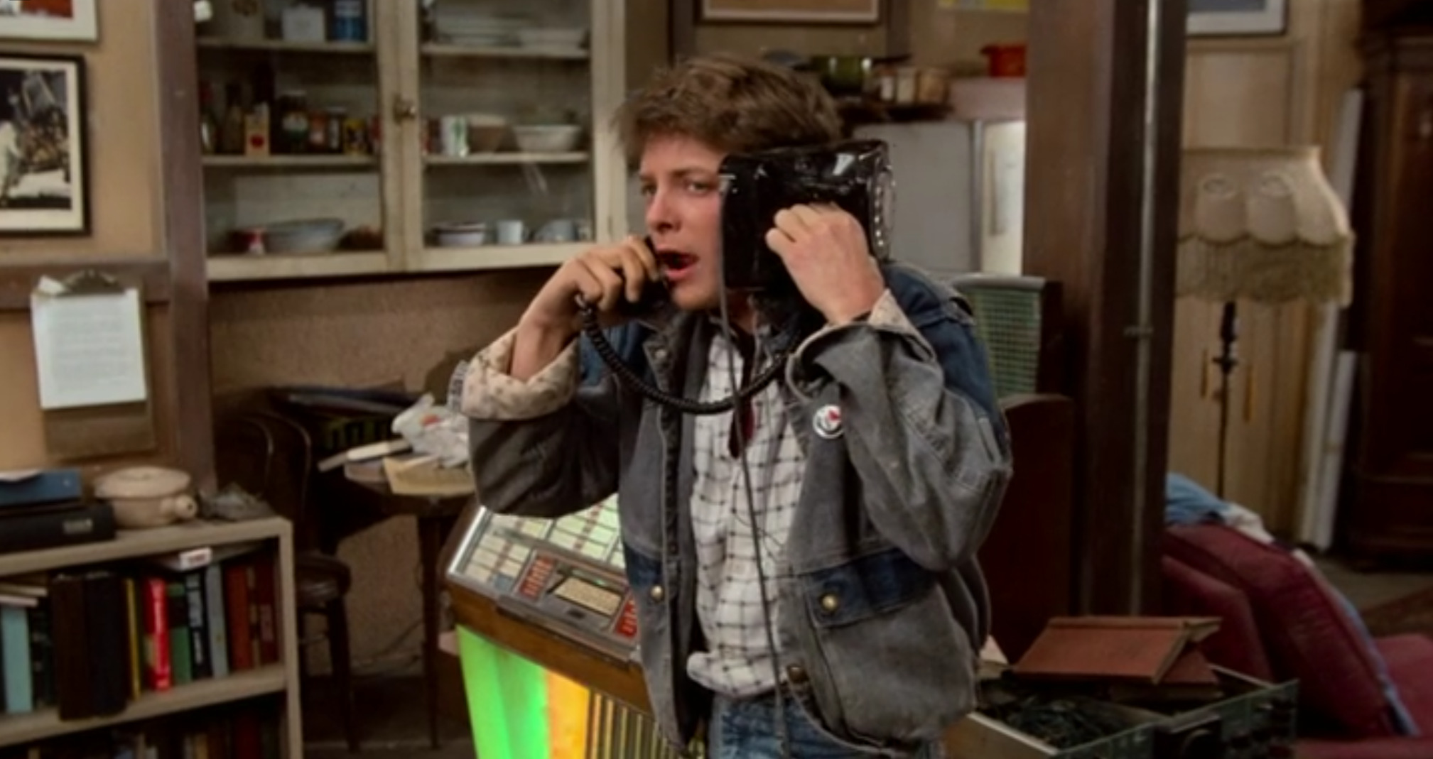
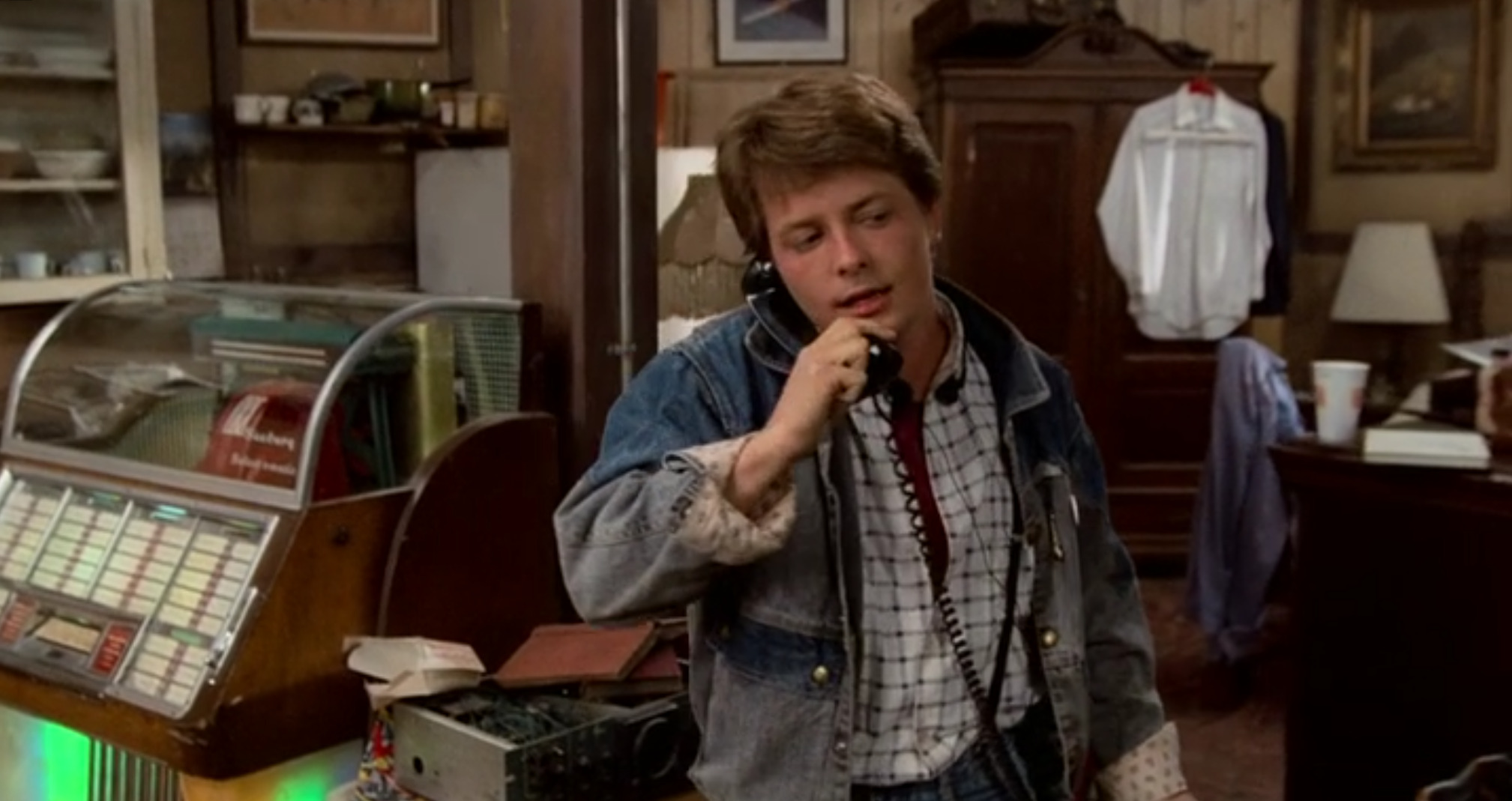
Like the pulse-dial and DTMF-based landline telephones the cordless telephone also gave way to cellphones and VoIP, but the old cordless telephones get a special mention because they were totally insecure. The radio signals they used were easily sniffed by anyone who knew how to operate a radio. To patch this technical vulnerability, the FCC made listening to particular frequencies illegal, and manufacturers cut out the cellphone and wireless phone bands from their scanners.

We see Marty in his double-bed on his cordless telephone.

And to wrap-up let’s give a special mention to the push-button Seeburg vinyl jukebox. These were commonplace back in the day and every good bar had a coin-operated one. These days you’re unlikely to find a jukebox at the bar, it is perhaps more likely that one of the bar staff is streaming music to the bar’s Bluetooth speakers from their smartphone.

We see Marty still on the phone to Doc, with the jukebox clearly visible to the left, and clothing draped over furniture in the back.

Thanks for coming with us on this brief journey back to 1985, it was fun to take some time to look at some of the things that have changed, and to pay our respects to this icon of hacker culture on its fortieth birthday. Don’t forget to sound-off in the comments regarding where you have seen references to the movie!

Building the Marauder LowRacer from Bike Parts

1 Julio 2025 at 05:00
Marauder LowRacer banner

Thanks to [Radical Brad] for writing in to let us know about his recent project, building a street racing bike from square tubing and old bike parts.

In this 50 minute video [Radical Brad] takes us through the process of building the Marauder v2, a street racing LowRacer. The entire build was done over a few weekends using only an AC welder, angle grinder, and basic hand tools you probably have in the garage.

The entire rear section of the Marauder is made from an unmodified stock rear triangle from a typical suspension mountain bike. The frame is made from 1.5″ mild steel square tubing with 1/16″ wall thickness, which is called “16 gauge tubing”.

[Radical Brad] runs you through the process of welding the pieces together at the appropriate angles along with some tips about how to clamp everything in place while you work on it. After completing the rear end he proceeds to the front end which uses the fork from the front of the old bike. A temporary seat is fashioned from some wooden boards joined together with hinges. Then the steering system is installed. Then the chains and pulleys for the motion system. Then the seat is finalized, and after a coat of paint, and installing some brakes, we’re done!

If you’re interested in projects for old bike parts you might like to check out Juice-Spewing Wind Turbine Bootstrapped From Bike Parts and Odd-Looking Mini EV Yard Tractor Is Made From Plywood And Bike Parts.

❌
❌