Radar made a huge impact when it was first invented, allowing objects to be detected using radio waves which would normally be difficult or impossible to observe through other means. Radio waves of all frequencies can be used for radar as well, whether that’s detecting ships beyond the horizon, tracking aircraft near an airport, penetrating the ground, or imaging objects with a high resolution. At the millimeter wavelength it’s fairly easy to detect humans with the right hardware, and using some inexpensive radar modules [Tech Dregs] shows us how to add this capability a home automation system.
Since these modules aren’t trying to image humans with fine detail or detect them at long range, the hardware can be fairly inexpensive. [Tech Dregs] is using the LD2410B modules which have not only an on-board microcontroller but also have the radio antennas used for radar built right onto the PCB. They have a simple binary output which can communicate whether or not a human is detected, but there’s also UART for communicating more details about what the module senses in the room. [Tech Dregs] is using this mode to connect the modules to Home Assistant, where they will be used to help automate his home’s lighting.
The only significant problem he had setting these modules up was getting them built into an enclosure. The short wavelengths used in this type of radar module don’t penetrate solid objects very well at all, so after trying to hide one behind an e-ink screen he eventually settled on hollowing out a space in a bezel with very thin plastic between the module and the room. If you need more out of your radar modules than object detection, though, you can always try building a pulse compression radar which can provide much more accurate ranging of objects.
Frustrated by his Aldi multimeter’s backlight turning off after just 15 seconds, [Steg Steg] took matters into his own hands. His solution? He added a manual toggle switch to control the backlight, allowing it to stay on as long as needed. He began by disassembling the multimeter—removing the outer bumper and a few screws—to access the backlight, labeled “BL.” He identified the voltage regulator outputting 2.8V, desoldered the red wire, and extended it to install the switch.
On his first try, he successfully drilled a spot for the SPST switch. To fit the switch into the multimeter’s rubber bumper, he used a circular punch, although his second hole wasn’t as clean as the first. Despite this minor setback, the modification worked perfectly, giving him complete control over his multimeter’s backlight without the original 15-second timeout.
In a modern car, your speedometer might look analog, but it is almost certainly digital and driven by the computer that has to monitor all sorts of things anyway. But how did they work before your car was a rolling computer complex? The electronic speedometer has been around for well over a century and, when you think about it, qualifies as a technlogical marvel.
If you already know how they work, this isn’t a fair question. But if you don’t, think about this. Your dashboard has a cable running into it. The inner part of the cable spins at some rate, which is related to either the car’s transmission or a wheel sensor. How do you make a needle deflect based on the speed?
Mechanical Solutions
Early versions of the speedometer used a governor pulling against a spring. The faster it rotates, the more the two weights of the governor pull out against the spring, and the needle moves with the weights.
As an aside, this sort of centrifugal governor is also known as a fly-ball governor, and similar devices were commonly used to regulate the maximum throttle on steam engines. The arms of the governor would be fully extended once the engine reached its top speed, which lead to the term “balls-out” becoming used to describe a machine operating at its upper limits.
Another type of mechanical speedometer had an escapement like a watch. The time mechanism would move the needle back, and the rotation of the wheels would move it forward. The net result was a needle position that would increase with speed.
The Magnetic Approach
However, most cars use a magnetic type speedometer — although it doesn’t work in the way you might imagine. There’s no reed relay or Hall effect sensing the magnetic field. Instead, there is an aluminum cup attached to the speedometer needle and, nearby, a magnet that spins on a shaft moving at some ratio of the car’s speed. There’s no direct connection between the two.
Being a non-ferrous metal, aluminum is not generally something we think of being affected by magnets. Under normal circumstances that might be true, but a moving magnetic field will induce eddy currents in aluminum. This forms a field in the aluminum, too, and the spinning magnet tends to drag the cup, thereby deflecting the pointer.
A spring similar to one you might find in a mechanical clock or watch pulls back the pointer so the needle hovers at the point where the force of the magnet pulls against the spring. The pull on the spring has to account for the gear ratios and the size of the tires to accurately reflect the vehicle’s speed.
If you want to see an entertaining teardown of an old speedometer, [Tubalcain/Mr Pete] has you covered in the video below. He also shows how the odometer part worked, too.
Modern Times
Of course, these days you are more likely to pick up a pulse using a Hall effect or some other part of the vehicle and just count the pulses in the car’s computer. In fact, the pulses might be encoded at the source and travel over something like a CAN bus to get to the computer.
It is also possible to pick up speed from other tracking information like GPS, although that might not be as accurate. But if you have, for example, a mobile phone app that shows your speed, that’s probably what it is doing. The obvious way to do that is to take position measurements periodically and then do the math. However, more sophisticated systems can actually measure Doppler shift to get a more accurate reading.
We see a lot of bicycle speedometers for some reason. Eddy currents make induction cooktops work, too. Even tiny ones.
Diamonds are nearly perfect crystals, but not totally perfect. The defects in these crystals give the stones their characteristic colors. But one type of defect, the NV — nitrogen-vacancy — center, can hold a particular spin, and you can change that spin with the correct application of energy. [Asianometry] explains why this is important in the video below.
Interestingly, even at room temperature, an NV center stays stable for a long time. Even more importantly, you can measure the spin nondestructively by detecting light emissions from the center.
There are obvious applications for quantum computing, but an even more practical application is sensing magnetic fields. These could replace SQUIDs, which are often used for sensitive magnetic measurements but require cold temperatures to support superconductivity.
Of course, you have to create a diamond artificially to get the NV centers the way you want and it turns out that semiconductor manufacturing tools can help produce the diamonds you need.
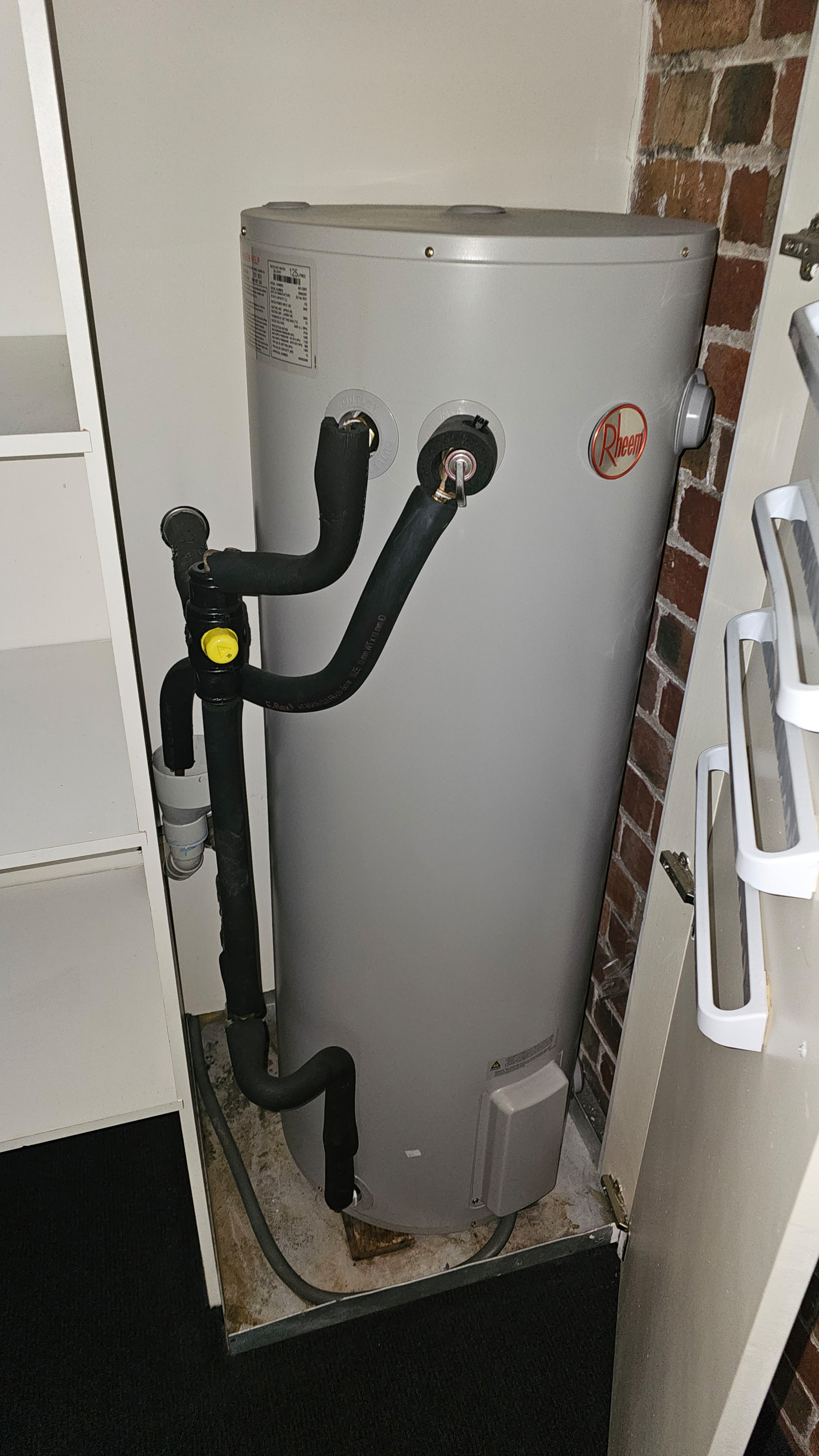
Australian grids have long run a two-tiered pricing scheme for electricity. In many jurisdictions, regular electricity was charged at a certain rate. Meanwhile, you could get cheaper electricity for certain applications if your home was set up with a “controlled load.” Typically, this involved high energy equipment like pool heaters or hot water heaters.
This scheme has long allowed Australians to save money while keeping their water piping-hot at the same time. However, the electrical grid has changed significantly in the last decade. These controlled loads are starting to look increasingly out of step with what the grid and the consumer needs. What is to be done?
Controlled What Now?
Hot water heaters can draw in excess of 5 kW for hours on end when warming up. Electrical authorities figured that it would be smart to take this huge load on the grid, and shift it to night time, a period of otherwise low demand. Credit: Lewin Day
In Australia, the electricity grid has long relied on a system of “controlled loads” to manage the energy demand from high-consumption appliances, particularly electric hot water heaters. These controlled loads were designed to take advantage of periods when overall electricity demand was lower, traditionally at night. By scheduling energy-intensive activities like heating water during these off-peak hours, utilities could balance the load on the grid and reduce the need for additional power generation capacity during peak times. In turn, households would receive cheaper off-peak electricity rates for energy used by their controlled load.
This system was achieved quite simply. Households would have a special “controlled load” meter in their electrical box. This would measure energy use by the hot water heater, or whatever else the electrical authority had allowed to be hooked up in this manner. The controlled load meter would be set on a timer so the attached circuit would only be powered in the designated off-peak times. Meanwhile, the rest of the home’s electrical circuits would be connected to the main electrical meter which would provide power 24 hours a day.
By and large, this system worked well. However, it did lead to more than a few larger families running out of hot water on the regular. For example, you might have had a 250 liter hot water heater. Hooked up as a controlled load, it would heat up overnight and switch off around 7 AM. Two or three showers later, the hot water heater would have delivered all its hot water, and you’d be stuck without any more until it switched back on at night.
Historically, most electric hot water heaters were set to run during the low-demand night period, typically after 10 PM. Historically, the demand for electricity was low at this time, while peak demand was in the day time. It made sense to take the huge load from everyone’s hot water system, and move all that demand to the otherwise quiet night period. This lowered the daytime peak, reducing demand on the grid, in turn slashing infrastructure and generation costs. It had the effect of keeping the demand curve flatter throughout the whole 24-hour period.
This strategy was particularly effective in a grid predominantly powered by coal-fired power stations, which operated most efficiently when running continuously at a stable output. By shifting the hot water heating load to nighttime, utilities could maintain a more consistent demand for electricity throughout the day and night, reducing the need for sudden increases in generation capacity during peak times.
Everything Changed
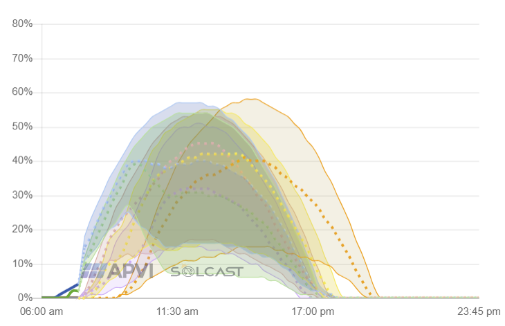
The Australian grid now sees large peaks in solar generation during the day. Credit: APVI.org.au via screenshot
However, the energy landscape in Australia has undergone a significant transformation in recent years. This has been primarily driven by the rapid growth of renewable energy sources, particularly home solar generation. As a result, the dynamics of electricity supply and demand have changed, prompting a reevaluation of the traditional approach to controlled loads.
Renewable energy has completely changed the way supply and demand works in the Australian grid. These days, energy is abundant while the sun is up. During the middle of the day, wholesale energy prices routinely plummet below $0.10 / kWh as the sun bears down on thousands upon thousands of solar panels across the country. Energy becomes incredibly cheap. Meanwhile, at night, energy is now very expensive. The solar panels are all contributing nothing, and it becomes the job of coal and gas generators to carry the majority of the burden. Fossil fuels are increasingly expensive, and spikes in the wholesale price are not uncommon, at times exceeding $10 / kWh.
Solar power generation peaks are now so high that Australian cities often produce more electricity than is needed to meet demand. This excess solar energy has led to periods where electricity prices can be very low, or even negative, due to the abundance of renewable energy on the grid. As a result, there is a growing argument that it now makes more sense to shift controlled loads, such as hot water heaters, to run during the daytime rather than at night.
The rise of home solar generation has created unexpected flow-on effects for Australia’s power grid. Credit: Wayne National Forest, CC BY 2.0
Shifting controlled loads to the daytime would help absorb the surplus solar energy. This would reduce the need for grid authorities to kick renewable generators off the grid in times of excess. It would also help mitigate the so-called “duck curve” effect, where the demand for electricity sharply increases in the late afternoon and early evening as solar generation declines, leading to a steep ramp-up in non-renewable generation. By using excess solar energy to power controlled loads during the day, the overall demand on the grid would be more balanced, and the reliance on fossil fuels during peak times could be reduced.
Implementing this shift would require adjustments to the current tariff structures and perhaps the installation of smart meters capable of dynamically managing when controlled loads are activated based on real-time grid conditions. In a blessed serendipity, some Australian states—like Victoria—have already achieved near-100% penetration of smart meters. Others are still in the process of rollout, aiming for near 100% coverage by 2030. While these changes would involve some initial investment, the long-term benefits, including greater integration of renewable energy, reduced carbon emissions, and potentially lower electricity costs for consumers, make it a compelling option.
Fundamentally, it makes no sense for controlled loads to continue running as they have done for decades. Millions of Australians are now paying to heat their water during higher-demand periods where energy is more expensive. This can be particularly punitive for those on regularly-updated live tariffs that change with the current wholesale energy price. Those customers will sit by, watching cheap solar energy effectively go to waste during a sunny day, before their water heater finally kicks at night when the coal generators are going their hardest.
While the traditional approach to controlled loads in Australia has served the grid well in the past, the rise of renewable energy has changed things. The abundance of solar generation necessitates a rethinking of when these loads are scheduled. By shifting the operation of controlled loads like hot water heaters to the daytime, Australia can make better use of its abundant renewable energy resources, improve grid stability, and move closer to its sustainability goals. It’s a simple idea that makes a lot of sense. Here’s waiting for the broader power authorities to step up and make the change.
We live in a time where there’s virtually no excuse not to have some kind of oscilloscope. As [IMSAI Guy] shows in a recent video, for what you might expect to pay for a decent meter, you can now get one that includes a scope. There are several options out there but it is hard to know how much to spend to get the best possible product. The Zoyi ZT-702S that he looks at costs under $80. But is it worth it?
Scopes that connect to your PC are often very inexpensive. You can also find little toy scopes that use a microcontroller and a little LCD screen. Even though the specs on these are usually appalling, they will still let you visualize what’s happening in a circuit. Sure, you want an expensive bench scope with lots of channels sometimes, but often, you just need to see a signal in broad strokes. Having a scope and a meter together is very handy.
The little meter claims 10 MHz bandwidth and 48 megasamples per second in scope mode. The meter claims true RMS and 9999 counts. The internal battery charges from USB-C. As you might expect, the meter portion works well enough for a basic meter. The scope reacts well up to 5 MHz. It isn’t necessarily the best scope in the world, but for $80 it seemed quite adequate. The probe compensation wasn’t able to quite make a square wave square, but you still got the idea.
As commenters on the video pointed out, there is a newer model that has two channels (at a slightly higher price tag). They also point out that there are dozens of similar devices at different price points, and everyone has their favorite.
If you have hobby-level cash, we’d suggest a higher-end scope meter like an OWON or Hantek since the professional brands are still very expensive. We wonder what the designer of 1983’s Pocket-O-Scope would think of these modern devices.
One can only imagine the wonders held within the crypto labs of organizations like the CIA or NSA. Therein must be machines of such sophistication that no electronic device could resist their attempts to defeat whatever security is baked into their silicon. Machines such as these no doubt bear price tags that only a no-questions-asked budget could support, making their techniques firmly out of reach of even the most ambitious home gamer.
That might be changing, though, with this $500 DIY laser fault injection setup. It comes to us from Finnish cybersecurity group [Fraktal], who have started a series of blog posts detailing how they built their open-source reverse-engineering rig. LFI is similar to other “glitching” attacks we’ve covered before, such as EMP fault injection, except that a laser shining directly on a silicon die is used to disrupt its operation rather than a burst of electromagnetic energy.
Since LFI requires shining the laser very precisely on nanometer-scale elements of a bare silicon die, nanopositioning is the biggest challenge. Rather than moving the device under attack, the [Fraktal] rig uses a modified laser galvanometer to scan an IR laser over the device. The galvo and the optical components are all easily available online, and they’ve started a repo to document the modifications needed and the code to tire everything together.
Of course, this technique requires the die in the device under study to be exposed, but [Fraktal] has made that pretty approachable too. They include instructions for milling away the epoxy from the lead-frame side of a chip, which is safer for the delicate structures etched into the top of the die. The laser can then shine directly through the die from the bottom. For “flip-chip” packages like BGAs, the same milling technique would be done from the top of the package. Either way, we can imagine a small CNC mill making the process safer and quicker, even though they seem to have done pretty well with a Dremel.
This looks like a fantastic reverse engineering tool, and we’re really looking forward to the rest of the story.
Fluke meters have been around for a long, long time. Heck, we’ve got a Fluke 73 that we bought back in 1985 that’s still a daily driver. But just because they’ve been making them forever doesn’t mean they last forever, and getting a secondhand meter back in the game can be a challenge. That’s what [TheHWCave] learned with his revival of a wonky eBay Fluke 25, an effort that holds lessons for anyone in the used Fluke market.
Initial inspection of the meter showed encouragingly few signs of abuse, somewhat remarkable for something built for the military in the early 1980s. A working display allowed a few simple diagnostics revealing that the ammeter functions seemed to work, but not the voltmeter and ohmmeter functions. [TheHWCave]’s teardown revealed a solidly constructed unit with no obvious signs of damage or blown fuses. Thankfully, a service schematic was available online, albeit one with a frustrating lack of detail, confusing test point nomenclature, and contradictory component values.
Despite these hurdles, [TheHWCave] was able to locate the culprit: a bad fusible power resistor. Finding a direct replacement wasn’t easy given the vagaries of the schematic and the age of the instrument, but he managed to track down a close substitute cheap enough to buy in bulk. He searched through 40 units to find the one closest to the listed specs, which got the meter going again. Fixing the bent pin also gave the meter back its continuity beeper, always a mixed blessing.
If you’re in the market for a meter but can’t afford the Fluke name, picking up a busted meter and fixing it up like this might be one way to go. But are they really worth the premium? Well, kinda yes.
[Jeff Sandberg] has put a fair bit of effort into adding solar and battery storage with associated smarts to his home, but his energy usage statistics were incomplete. His solution was to read data from the utility meter using RTL-SDR to fill in the blanks. The results are good so far, and there’s no reason similar readings for gas and water can’t also be done.
[Jeff] uses the open source home automation software Home Assistant which integrates nicely with his solar and battery backup system, but due to the way his house is wired, it’s only aware of about half of the energy usage in the house. For example, [Jeff]’s heavy appliances get their power directly from the power company and are not part of the solar and battery systems. This means that Home Assistant’s energy statistics are incomplete.
Fortunately, in the USA most smart meters broadcast their data in a manner that an economical software-defined radio like RTL-SDR can access. That provided [Jeff] with the data he needed to get a much more complete picture of his energy usage.
While getting data from utility meters is conceptually straightforward, actually implementing things in a way that integrated with his system took a bit more work. If you’re finding yourself in the same boat, be sure to look at [Jeff]’s documentation to get some ideas.
AVO meters — literally amp, volt, ohm meters — are not very common in North America but were staples in the UK. [TheHWcave] found an AVO 8 that is probably from the 1950s or 1960s and wanted to get it working. You can see the project in the video below.
These are very different from the standard analog meters many of us grew up with. [TheHWcave] shows how the dual range knobs work together to set the measurement. There are three separate ohm settings, and each one has its own zero pot. We were surprised that the meter didn’t have a parallax-correcting mirror.
Other than dirty switch contacts, the voltage measurements still worked. After cleaning the contacts, most of the ranges worked well, although there were still some issues. Some of the resistor ranges were not working, either. Inside the case were an old D cell and a square battery, a B121 15 V battery. Replacing the 15 V battery with a bench supply made things better.
Some plugins are available to allow the meter to read low resistance or high currents. We thought using the soldering gun as a current source was clever. Once he gets it working, he opens the box around the 14:30 mark.
The inside was all hand-wiring and power resistors. Of course, there are also a ton of contacts for the switches. So it isn’t just an electrical design, but a mechanical one, too. The electrical design is also interesting, and an analysis of it winds the video down.
If you’re instrumenting your machine tools, or if you’re just curious, you might want to get granular access to the output of a digital micrometer or the like. [Tommy] set his mind to figuring out the communications protocol of the ClockWise Tools dial indicator for this very purpose. And he succeeded!
Work began by finding the clock and signal lines for the gauge. With those identified, and the signals up on an AD2 logic analyzer, it was determined that once every 40 milliseconds, the device sent a data burst of six nibbles separated by 1.58 milliseconds apiece. The device communicates the absolute position of the gauge, and the data can be readily decoded with the aid of an op-amp to help boost up the 1.5-volt logic to a more reasonable level for a modern commodity microcontroller like the Arduino Nano. From there, the information can be trucked over serial to a PC, or you can do just about anything else with it besides.
We’ve seen similar hacks performed on calipers before, too, making automated measurements a breeze. If you’re working on something that needs precise measurements down to the, well… micrometer… this project might be just the thing you’re looking for.
Non-contact infrared (IR) thermometers used to be something of an exotic tool, but thanks at least in part due to the COVID-19 pandemic, they’re now the sort of thing you see hanging up near the grocery store checkout as a cheap impulse buy. Demand pushed up production, and the economies of scale did the test. Now the devices, and the sensors within them, are cheap enough for us hackers to play with.
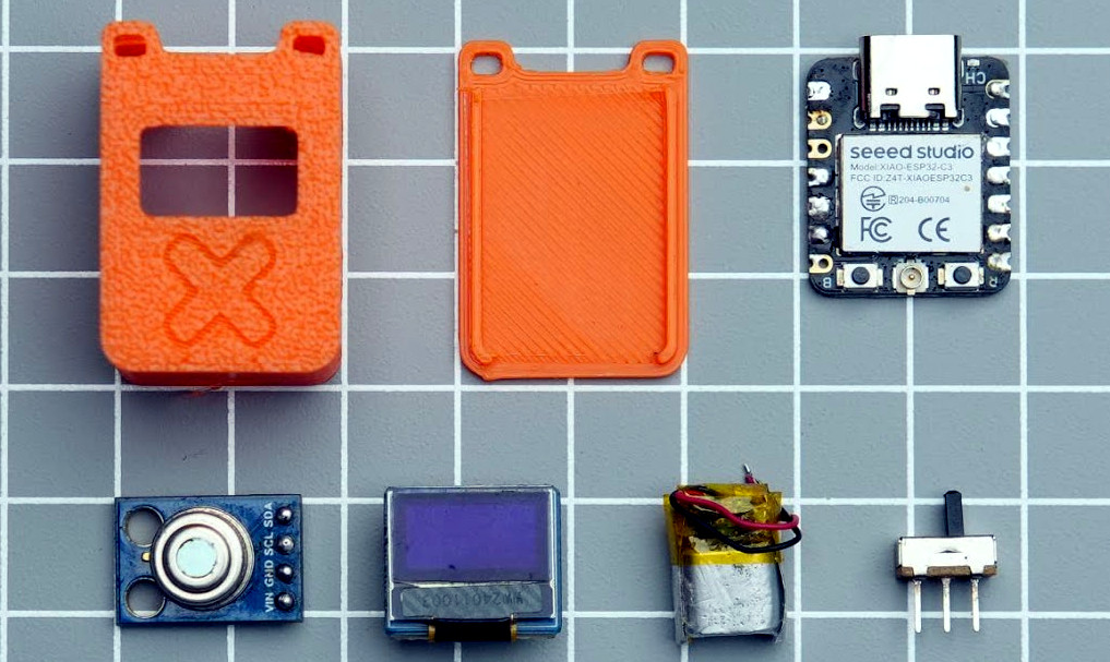
The end result is that we now have projects like this ultra compact IR thermometer from [gokux]. With just a handful of components, some code to glue it all together, and a 3D printed enclosure to wrap it all up, you’ve got a legitimately useful tool that’s small enough to replace that lucky rabbit’s foot you’ve got on your keys.
If this project looks familiar, it’s because the whole thing is closely related to the LiDAR rangefinder [gokux] put together last month. It shares the same Seeed Studio XIAO ESP32-C3 microcontroller, 0.49 inch OLED display, and tiny 40 mAh LiPo battery. The only thing that’s really changed, aside from the adjustments necessary to the 3D printed enclosure, is that the LiDAR sensor was replaced with a MLX90614 IR temperature sensor.
[gokux] has put together some great documentation for this build, making it easy for others to recreate and remix on their own. Assembly is particularly straightforward thanks to the fact that both the display and temperature sensor communicate with the ESP32 over I2C, allowing them to be wired daisy chain style — there’s no need for even a scrap of perfboard inside the case, let alone a custom board.
It’s official: [Engineer Bo] wins the internet with a video titled “Finding NEMA 17,” wherein he builds a dynamometer to find the best stepper motor in the popular NEMA 17 frame size.
Like a lot of subjective questions, the only correct answer to which stepper is best is, “It depends,” and [Bo] certainly has that in mind while gathering the data needed to construct torque-speed curves for five samples of NEMA 17 motors using his homebrew dyno. The dyno itself is pretty cool, with a bicycle disc brake to provide drag, a load cell to measure braking force, and an optical encoder to measure the rotation of the motor under test. The selected motors represent a cross-section of what’s commonly available today, some of which appear in big-name 3D printers and other common applications.
[Bo] tested each motor with two different drivers: the TMC2209 silent driver to start with, and because he released the Magic Smoke from those, the higher current TB6600 module. The difference between the two drivers was striking, with lower torque and top speeds for the same settings on each motor using the TB6600, as well as more variability in the data. Motors did better across the board with the TBC6600 at 24 volts, showing improved torque at higher speeds, and slightly higher top speeds. He also tested the effect of microstepping on torque using the TBC6600 and found that using full steps resulted in higher torque across a greater speed range.
At the end of the day, it seems as if these tests say more about the driver than they do about any of the motors tested. Perhaps the lesson here is to match the motor to the driver in light of what the application will be. Regardless, it’s a nice piece of work, and we really appreciate the dyno design to boot — reminds us of a scaled-down version of the one [Jeremey Fielding] demonstrated a few years back.