Vista Normal

Hay nuevos artículos disponibles. Pincha para refrescar la página.
Ayer — 17 Julio 2024IT And Programming

FDM Filament Troubles: Keeping Hygroscopic Materials From Degrading

Por: Maya Posch
17 Julio 2024 at 14:20

Despite the reputation of polymers used with FDM 3D printing like nylon, ABS, and PLA as being generally indestructible, they do come with a whole range of moisture-related issues that can affect both the printing process as well as the final result. While the concept of ‘baking’ such 3D printing filaments prior to printing to remove absorbed moisture is well-established and with many commercial solutions available, the exact extent to which these different polymers are affected, and what these changes look like on a molecular level are generally less well-known.

Another question with such hygroscopic materials is whether the same issues of embrittlement, swelling, and long-term damage inflicted by moisture exposure that affects filaments prior to printing affects these materials post-printing, and how this affects the lifespan of FDM-printed items. In a 2022 paper by Adedotun D. Banjo and colleagues much of what we know today is summarized in addition to an examination of the molecular effects of moisture exposure on polylactic acid (PLA) and nylon 6.

The scientific literature on FDM filaments makes clear that beyond the glossy marketing there is a wonderful world of materials science to explore, one which can teach us a lot about how to get good FDM prints and how durable they will be long-term.

Why Water Wrecks Polymers

Although the effects of moisture exposure on FDM filaments tend to get tossed together into a simplified model of ‘moisture absorption’, there are actually quite different mechanisms at play for these different polymers. A good example of this from the Banjo et al paper is the difference between nylon 6 and polylactic acid (PLA). While nylon 6 is very hygroscopic, PLA is mostly hydrophobic, yet this does not save PLA from getting degraded as well from moisture exposure.

Molecular structure of base polymers nylon 6 and polylactic acid (PLA).

In the case of nylon 6 (C6H11NO), the highly polar functional groups such as amides (−C(=O)−(N) ), amines (−NH2) and carbonyls (C=O) make this polymer hydrophilic. As these functional groups are exposed to moisture, the resulting hydrolysis of the amide bonds gradually affects the material properties of the polymer like its tensile strength.

A few percent moisture in the polymer filament prior to passing through the hot extruder of an FDM printer will correspondingly cause issues as this moisture rapidly evaporates. And after printing a nylon object, moisture will once again hydrolyze the amide bonds, weakening the material over time. This is something that can be avoided somewhat by sealing the object against moisture intrusion, but this is rarely practical for functional parts. This degradation of polyamides can be observed by the cracking of nylon gears in toys gearboxes, servo motors, and similar high-stress applications.

In the case of PLA ((C3H4O2)n), far fewer polar functional groups are present, making PLA effectively hydrophobic, although it is soluble in various organic solvents like ethyl acetate. PLA’s weakness lies in its ester bonds, which are subject to hydrolysis and can thus be broken like amides. This type of hydrolysis in PLA is very slow, however, with studies finding that it barely degrades even submerged in water. The often cited ‘composting’ of PLA thus requires chemical hydrolysis, making options like incineration the faster and easier route for disposal. As a result, for long-term stability PLA does rate highly, regardless of its other material properties.

Naturally, in the case of all hygroscopic polymers the rate of degradation depends on both the moisture content of the air, and the temperature. In the earlier referenced study by D. Banjo et al., the FDM printed samples were fully submerged into water to accelerate the process, with three types of polymers tested at 21 °C and 70 °C.

Freshly Baked Polymer

Drawing the moisture out of the polymer again can be done in a variety of ways, with applying heat over an extended period of time being the most common. The application of thermal energy motivates the water molecules to make their way out of the polymer again, but it is important to understand here that hydrolysis is a permanent, non-reversible process. This means that the focus is primarily on removing any absorbed water that can be problematic during extrusion, and to prevent further degradation of the polymer over time.

A paper presented by Xuejun Fan at the IEEE EuroSimE conference in 2008 titled “Mechanics of Moisture for Polymers: Fundamental Concepts and Model Study” covers the fundamental concepts related to moisture intrusion which ultimately enable the degradation. In particular it is of note that the effects of submersion (water sorption) versus exposure to the air (moisture sorption) lead to very different transport mechanisms, and that there’s a distinction between bound and unbound water inside the polymer. This unbound water is contained within microscopic pores that exist within the material, and would thus be a good target for forced eviction using thermal means.

Exactly how much heat has to be applied and for which duration differs wildly, based mostly on the type of material, with commercial filament dryers generally having presets programmed into them. Filament drying charts are available from a wide variety of sources, such from Bambu Lab. They recommend drying PLA filament at 50 °C – 60 °C for eight hours, while Prusa recommends drying PLA for six hours at 45 °C (and PA11CF reinforced nylon at 90 °C). This highlights just how hard it is to make definite statements here other than not heating up a spool of filament to the point where it softens and sticks together. The question of ‘how long’ would be ideally answered with ‘until all the moisture is gone’, but since this is hard to quantify without specialized equipment, longer can be said to be better.

Perhaps the biggest take-away here is that preventing moisture from getting even near the polymer is by far the best option, meaning that keeping spools of filament in vacuum bags with desiccant gel between printing sessions is highly recommended.

Endurance

Flexural yield strength (σY) of 3D printed materials after immersion in DI water at 21 °C and 70 °C (a) Nylon (b) Nylon Composite (c) PLA. Error bars reflect one standard deviation of data. (Credit: D. Banjo et al., 2022)

If water molecules cause physical damage to the polymer structure, how severe is the impact? Obviously having unbound moisture in the filament is a terrible thing when trying to melt it for printing, but how long can an FDM printed part be expected to last once it’s finished and put into use in some kind of moist environment?

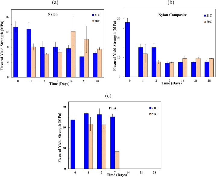
For PLA and nylon we can see the effects illustrated in the D. Banjo et al. study, with parameters like moisture absorption, crystallinity changes, and mechanical performance examined.

Perhaps most fascinating about these results is the performance of PLA, which at first appears to outperform nylon, as the latter initially shows a sharp decrease in mechanical properties early on. However, nylon stabilizes while PLA’s properties at either temperature water completely fall off a cliff after about a week of being submerged. This brittleness of PLA is already its main weakness when it’s not subjected to hydrolysis, and clearly accelerated aging in this fashion shows just how quickly it becomes a liability.

The big asterisk here is of course that this study used an absolute worst-case scenario for FDM-printed polymers, with water sorption in relatively warm to very warm water. Even so, it’s illustrative of just how much different polymers can differ, and why picking the optimal polymer for an FDM print completely depends on the environment. Clearly PLA is totally fine for many situations where its disadvantages are not an issue, while for more demanding situations nylon, ABS/ASA, or PC may be the better choice.

Keeping filament dry, vacuum-packed and far away from moisture will significantly improve printing with it as well as its longevity. Printed parts can have their surface treated to seal them against moisture, which can make them last much longer without mechanical degradation. Ultimately FDM printing is just a part of the messy world of materials science and manufacturing, both of which are simultaneously marvels of modern science while also giving engineers terrible nightmares.

AnteayerIT And Programming

Smart Ball Technology Has Reached Football, But The Euros Show Us It’s Not Necessarily For The Better

Por: Lewin Day
16 Julio 2024 at 14:00
Adidas brought smart balls to Euro 2024, for better or worse. Credit: Adidas

The good old fashioned game of football used to be a simple affair. Two teams of eleven, plus a few subs, who were all wrangled by a referee and a couple of helpful linesmen. Long ago, these disparate groups lived together in harmony. Then, everything changed when VAR attacked.

Suddenly, technology was being used to adjudicate all kinds of decisions, and fans were cheering or in uproar depending on how the hammer fell. That’s only become more prevalent in recent times, with smart balls the latest controversial addition to the world game. With their starring role in the Euro 2024 championship more than evident, let’s take a look at what’s going on with this new generation of intelligent footballs.

The Balls Are Connected

Adidas supports the sensor package in the very center of the ball. Credit: Adidas

Adidas has been a pioneer of so-called “connected ball” technology. This involves fitting match balls with motion sensors which can track the motion of the ball in space. The aim is to be able to track the instant of player contact with the ball, for investigating matters like calls of handball and offside. The German country first debuted the technology at the 2022 World Cup, and it showed up at the 2023 Women’s World Cup and the UEFA Euro 2024 championship, too.

According to Adidas, an inertial measurement unit is suspended in the middle of the ball. This is done with a delicate structure that holds the IMU stably in place without impacting the performance of the ball from the player’s perspective. Powering the TDK ICM-20649 IMU is a small battery that can be recharged using an induction system. The IMU runs at a rate of 500 Hz, allowing hits to the ball to be measured down to tiny fractions of a second. The ball also features a DW1000 ultra-wideband radio system for position tracking, developed by Kinexion.

Connected balls allow the collection of statistics down to a very granular level, as seen here in the 2023 Women’s World Cup. Credit: Adidas

No more must match officials rely on their own perception, or even blurry video frames, to determine if a player touched the ball. Now, they can get a graphical readout showing acceleration spikes when a players foot, hand, or other body part impinges on the motion of the ball. This can then be used by the on-field referee and the video assistant referee to determine the right call more accurately. The idea is that this data removes a lot of the confusion from the refereeing process, giving officials exacting data on when a player may have touched the ball and when. No more wondering if this ball came close, or if that ball ricocheted based on a rough camera angle. What really happened is now being measured, and the data is all there for the officials to see, clear as day. What could be better, right?

Case In Point

A review of the incident showed the ball had grazed Andersen’s fingers, leading to a penalty declared for handball. via Optus Sport, YouTube

The UEFA Euro 2024 championship was the latest battleground to showcase this technology. As the national teams of Europe went in to play critical matches, players and fans alike knew that this technology would be on hand to ensure the fairest playing field yet. You might think that it would leave everyone feeling happier about how their favored team got treated, but as always, humans don’t react so predictably when emotions are hot and national pride is on the line.

The match between Germany and Denmark was the perfect example of how technology could sway a game, one way or the other. The Video Assistant Referee killed Denmark’s first goal with a ruling from the Semi-Automated Offside Technology system, and the ball technology would soon curse the Danes, too. As Germany’s David Raum crossed the ball, it ever so slightly clipped the hand of Danish player Joachim Andersen. In the past, this might have gone unnoticed, or at the least unpunished. But in today’s high-tech world, there was data to reveal the crime in explicit detail.

As the video replays showed the footage, we were treated to a graph indicating the spike picked up by the ball’s sensors just as it clipped Andersen’s hand in the video. The referee thus granted a penalty for the handball, which has duly slotted home by German striker Kai Havertz. Germany would go on to win the match 2-0, with midfielder Jamal Musiala scoring the follow-up.

The incident inflamed fans and pundits alike, with the aftermath particularly fiery on ITV. “If he didn’t pay that, if he did pay that, we’d be saying, okay, he saw it that way,” said football manager Ange Postecoglou, noting that the technology was creating frustration in a way that traditional referring decisions did not. Meanwhile, others noted that the technology is, to a degree, now in charge. “[Referee] Michael Oliver cannot go to that monitor and say I refuse to take that recommendation,” said VAR pundit Christina Unkel. “This has been issued by FIFA as what he needs to take for consistency across the world.”

Fundamentally, smart ball technology is not so different from other video assist technologies currently being used in football. These tools are flooding in thick and fast for good reason. They are being introduced to reduce variability in refereeing decisions, and ultimately, to supposedly improve the quality of the sport.

Sadly, though, smart balls seem to be generating much the same frustration as VAR has done so in the past. It seems when a referee is solely at fault for a decision, the fans can let it go. However, when a smart ball or a video referee disallows a goal because of a matter of some inches or millimeters, there’s an uproar so predictable that you can set your watch to it.

Given the huge investment and the institutional backing, don’t expect these technologies to go away any time soon. Similarly, expect fan outrage to blossom most every time they are they used. For now, smart balls and VAR have the backing they need to stay on, so you’d best get used to them for now.

Embedded Python: MicroPython Is Amazing

11 Julio 2024 at 14:00

In case you haven’t heard, about a month ago MicroPython has celebrated its 11th birthday. I was lucky that I was able to start hacking with it soon after pyboards have shipped – the first tech talk I remember giving was about MicroPython, and that talk was how I got into the hackerspace I subsequently spent years in. Since then, MicroPython been a staple in my projects, workshops, and hacking forays.

If you’re friends with Python or you’re willing to learn, you might just enjoy it a lot too. What’s more, MicroPython is an invaluable addition to a hacker’s toolkit, and I’d like to show you why.

Hacking At Keypress Speed

Got a MicroPython-capable chip? Chances are, MicroPython will serve you well in a number of ways that you wouldn’t expect. Here’s a shining example of what you can do. Flash MicroPython onto your board – I’ll use a RP2040 board like a Pi Pico. For a Pico, connect an I2C device to your board with SDA on pin 0 and SCL on pin 1, open a serial terminal of your choice and type this in:

>>> from machine import I2C, Pin
>>> i2c = I2C(0, sda=Pin(0), scl=Pin(1))
>>> i2c.scan()

This interactivity is known as REPL – Read, Evaluate, Print, Loop. The REPL alone makes MicroPython amazing for board bringup, building devices quickly, reverse-engineering, debugging device library problems and code, prototyping code snippets, writing test code and a good few other things. You can explore your MCU and its peripherals at lightning speed, from inside the MCU.

When I get a new I2C device to play with, the first thing I tend to do is wiring it up to a MicroPython-powered board, and poking at its registers. It’s as simple as this:

>>> for i in range(16):
>>>     # read out registers 0-15
>>>     # print "address value" for each
>>>     print(hex(i), i2c.readfrom_mem(0x22, i))
>>> # write something to a second (0x01) register
>>> i2c.writeto_mem(0x22, 0x01, bytes([0x01]) )

That i2c.scan() line alone replaces an I2C scanner program you’d otherwise have to upload into your MCU of choice, and you can run it within three to five seconds. Got Micropython running? Use serial terminal, Ctrl+C, and that will drop you into a REPL, just type i2c.scan() and press Enter. What’s more, you can inspect your code’s variables from the REPL, and if you structure your code well, even restart your code from where it left off! This is simply amazing for debugging code crashes, rare problems, and bugs like “it stops running after 20 days of uptime”. In many important ways, this removes the need for a debugger – you can now use your MCU to debug your code from the inside.

Oh, again, that i2c.scan()? You can quickly modify it if you need to add features on the fly. Want addresses printed in hex? (hex(addr) for addr in i2c.scan()). Want to scan your bus while you’re poking your cabling looking for a faulty wire? Put the scan into a while True: and Ctrl+C when you’re done. When using a typical compiled language, this sort of tinkering requires an edit-compile-flash-connect-repeat cycle, taking about a dozen seconds each time you make a tiny change. MicroPython lets you hack at the speed of your keyboard typing. Confused the pins? Press the `up` button, edit the line and run the i2c = line anew.

To be clear, all of code is running on your microcontroller, you just type it into your chip’s RAM and it is executed by your MCU. Here’s how you check GPIOs on your Pi Pico, in case you’re worried that some of them have burnt out:

>>> from machine import Pin
>>> from time import sleep
>>> pin_nums = range(30) # 0 to 29
>>> # all pins by default - remove the ones connected to something else if needed
>>> pins = [Pin(num, Pin.OUT) for num in pin_nums]
>>> 
>>> while True:
>>>   # turn all pins on
>>>   for i in range(len(pins)):
>>>     pins[i].value(True)
>>>   sleep(1)
>>>   # turn all pins off
>>>   for i in range(len(pins)):
>>>     pins[i].value(False)
>>>   sleep(1)
>>>   # probe each pin with your multimeter and check that each pin changes its state

There’s many things that make MicroPython a killer interpreter for your MCU. It’s not just the hardware abstraction layer (HAL), but it’s also the HAL because moving your code from board to board is generally as simple as changing pin definitions. But it’s all the other libraries that you get for free that make Python awesome on a microcontroller.

Batteries Included

It really is about the batteries – all the libraries that the stock interpreter brings you, and many more that you can download. Only an import away are time, socket, json, requests, select, re and many more, and overwhelmingly, they work the same as CPython. You can do the same r = requests.get("https://retro.hackaday.com"); print(r.text)[:1024] as you would do on desktop Python, as long as you got a network connection going on. There will be a few changes – for instance, time.time() is an integer, not a float, so if you need to keep track of time very granularly, there are different functions you can use.

Say, you want to parse JSON from a web endpoint. If you’re doing that in an Arduino environment, chances are, you will be limited in what you can do, and you will get triangle bracket errors if you mis-use the JSON library constructs because somehow the library uses templates; runtime error messages are up to you to implement. If you parse JSON on MicroPython and you expect a dict but get a list in runtime, it prints a readable error message. If you run out of memory, you get a very readable MemoryError printed out, you can expect it and protect yourself from it, even fix things from REPL and re-run the code if needed.

The user-supplied code is pretty good, too. If you want PIO or USB-HID on the RP2040, or ESP-CPU-specific functions on the ESP family, they are exposed in handy libraries. If you want a library to drive a display, it likely already has been implemented by someone and put on GitHub. And, if that doesn’t exist, you port one from Arduino and publish it; chances are, it will be shorter and easier to read. Of course, MicroPython has problems. In fact, I’ve encountered a good few problems myself, and I would be amiss not mentioning them.

Mind The Scope

In my experience, the single biggest problem with MicroPython is that writing out `MicroPython` requires more of my attention span than I can afford. I personally shorten it to uPy or just upy, informally. Another problem is that the new, modernized MicroPython logo has no sources or high-res images available, so I can’t print my own stickers of it, and MicroPython didn’t visit FOSDEM this year, so I couldn’t replenish my sticker stock.

On a more serious note, MicroPython as a language has a wide scope of where you can use it; sometimes, it won’t work for you. An ATMega328P can’t handle it – but an ESP8266 or ESP32 will easily, without a worry in the world, and you get WiFi for free. If you want to exactly control what your hardware does, counting clock cycles or hitting performance issues, MicroPython might not work for you – unless you write some Viper code.

If you want to have an extremely-low-power MCU that runs off something like energy harvesting, MicroPython might not work – probably. If you need your code run instantly once your MCU gets power, mind the interpreter takes a small bit of time to initialize – about one second, in my experience. If you want to do HDMI output on a RP2040, perhaps stick to C – though you can still do PIO code, there are some nice libraries for it.

Some amount of clock cycles will be spent on niceties that Python brings. Need more performance? There are things you can do. For instance, if you have a color display connected over SPI and you want to reduce frame rendering time, you might want to drop down to C, but you don’t have to ditch MicroPython – just put more of your intensive code into C-written device drivers or modules you compile, and, prototype it in MicroPython before you write it.

As Seen On Hackaday

If you’ve followed the USB-C PD talking series, you must’ve seen that the code was written in MicroPython, and I’ve added features like PD sniffing, DisplayPort handling and PSU mode as if effortlessly; it was just that easy to add them and more. I started with the REPL, a FUSB302 connected to a RP2040, poking at registers and reading the datasheet, and while I needed outside help, the REPL work was so so much fun!

There’s something immensely satisfying about poking at a piece of technology interactively and trying to squeeze features out of it, much more if it ends up working, which it didn’t, but it did many other times! I’ve been hacking on that PD stack, and now I’m slowly reformatting it from a bundle of functions into object-based code – Python makes that a breeze.

Remember the Sony Vaio board? Its EC (embedded controller) is a RP2040, always powered on as long as batteries are inserted, and it’s going to be running MicroPython. The EC tasks include power management, being a HID over I2C peripheral, button and LED control, and possibly forwarding keyboard and trackpoint events to save a USB port from the second RP2040, which will run QMK and server as a keyboard controller. MicroPython allows me to make the firmware quickly, adorn it with a dozen features while I do it, and keep the codebase expandable on a whim. The firmware implementation will be a fun journey, and I hope I can tell about it at some point.

Have you used MicroPython in your projects? What did it bring to your party?

Solar Dynamics Observatory: Our Solar Early Warning System

9 Julio 2024 at 14:00

Ever since the beginning of the Space Age, the inner planets and the Earth-Moon system have received the lion’s share of attention. That makes sense; it’s a whole lot easier to get to the Moon, or even to Mars, than it is to get to Saturn or Neptune. And so our probes have mostly plied the relatively cozy confines inside the asteroid belt, visiting every world within them and sometimes landing on the surface and making a few holes or even leaving some footprints.

But there’s still one place within this warm and familiar neighborhood that remains mysterious and relatively unvisited: the Sun. That seems strange, since our star is the source of all energy for our world and the system in general, and its constant emissions across the electromagnetic spectrum and its occasional physical outbursts are literally a matter of life and death for us. When the Sun sneezes, we can get sick, and it has the potential to be far worse than just a cold.

While we’ve had a succession of satellites over the last decades that have specialized in watching the Sun, it’s not the easiest celestial body to observe. Most spacecraft go to great lengths to avoid the Sun’s abuse, and building anything to withstand the lashing our star can dish out is a tough task. But there’s one satellite that takes everything that the Sun dishes out and turns it into a near-constant stream of high-quality data, and it’s been doing it for almost 15 years now. The Solar Dynamics Observatory, or SDO, has also provided stunning images of the Sun, like this CGI-like sequence of a failed solar eruption. Images like that have captured imaginations during this surprisingly active solar cycle, and emphasized the importance of SDO in our solar early warning system.

Living With a Star

In a lot of ways, SDO has its roots in the earlier Solar and Heliospheric Observer, or SOHO, the wildly successful ESA solar mission. Launched in 1995, SOHO is stationed in a halo orbit at Lagrange point L1 and provides near real-time images and data on the sun using a suite of twelve science instruments. Originally slated for a two-year science program, SOHO continues operating to this day, watching the sun and acting as an early warning for coronal mass ejections (CME) and other solar phenomena.

Although L1, the point between the Earth and the Sun where the gravitation of the two bodies balances, provides an unobstructed view of our star, it has disadvantages. Chief among these is distance; at 1.5 million kilometers, simply getting to L1 is a much more expensive proposition than any geocentric orbit. The distance also makes radio communications much more complicated, requiring the specialized infrastructure of the Deep Space Network (DSN). SDO was conceived in part to avoid some of these shortcomings, as well as to leverage what was learned on SOHO and to extend some of the capabilities delivered by that mission.

SDO stemmed from Living with a Star (LWS), a science program that kicked off in 2001 and was designed to explore the Earth-Sun system in detail. LWS identified the need for a satellite that could watch the Sun continuously in multiple wavelengths and provide data on its atmosphere and magnetic field at an extremely high rate. These requirements dictated the specifications of the SDO mission in terms of orbital design, spacecraft engineering, and oddly enough, a dedicated communications system.

Geosynchronous, With a Twist

Getting a good look at the Sun for space isn’t necessarily as easy as it would seem. For SDO, designing a suitable orbit was complicated by the stringent and somewhat conflicting requirements for continuous observations and constant high-bandwidth communications. Joining SOHO at L1 or setting up shop at any of the other Lagrange points was out of the question due to the distances involved, leaving a geocentric orbit as the only viable alternative. A low Earth orbit (LEO) would have left the satellite in the Earth’s shadow for half of each revolution, making continuous observation of the Sun difficult.

To avoid these problems, SDO’s orbit was pushed out to geosynchronous Earth orbit (GEO) distance (35,789 km) and inclined to 28.5 degrees relative to the equator. This orbit would give SDO continuous exposure to the Sun, with just a few brief periods during the year where either Earth or the Moon eclipses the Sun. It also allows constant line-of-sight to the ground, which greatly simplifies the communications problem.

Science of the Sun

SDO packaged for the trip to geosynchronous orbit. The solar array corners are clipped to provide clearance for the high-gain dishes when the Earth is between SDO and the Sun. The four telescopes of AIA are visible on the top with EVE and HMI on the other edge above the stowed dish antenna. Source: NASA

The main body of SDO has a pair of solar panels on one end and a pair of steerable high-gain dish antennas on the other. The LWS design requirements for the SDO science program were modest and focused on monitoring the Sun’s magnetic field and atmosphere as closely as possible, so only three science instruments were included. All three instruments are mounted to the end of the spaceframe with the solar panels, to enjoy an unobstructed view of the Sun.

Of the three science packages, the Extreme UV Variability Experiment, or EVE, is the only instrument that doesn’t image the full disk of the Sun. Rather, EVE uses a pair of multiple EUV grating spectrographs, known as MEGS-A, and MEGS-B, to measure the extreme UV spectrum from 5 nm to 105 nm with 0.1 nm resolution. MEGS-A uses a series of slits and filters to shine light onto a single diffraction grating, which spreads out the Sun’s spectrum across a CCD detector to cover from 5 nm to 37 nm. The MEGS-A CCD also acts as a sensor for a simple pinhole camera known as the Solar Aspect Monitor (SAM), which directly measures individual X-ray photons in the 0.1 nm to 7 nm range. MEGS-B, on the other hand, uses a pair of diffraction gratings and a CCD to measure EUV from 35 nm to 105 nm. Both of these instruments capture a full EUV spectrum every 10 seconds.

To study the corona and chromosphere of the Sun, the Atmospheric Imaging Assembly (AIA) uses four telescopes to create full-disk images of the sun in ten different wavelengths from EUV to 450 nm. The 4,096 by 4,096 sensor gives the AIA a resolution of 0.6 arcseconds per pixel, and the optics allow imaging out to almost 1.3 solar radii, to capture fine detail in the thin solar atmosphere. AIA also visualizes the Sun’s magnetic fields as the hot plasma gathers along lines of force and highlights them. Like all the instruments on SDO, the AIA is built with throughput in mind; it can gather a full data set every 10 seconds.

For a deeper look into the Sun’s interior, the Helioseismic and Magnetic Imager (HMI) measures the motion of the Sun’s photosphere and magnetic field strength and polarity. The HMI uses a refracting telescope, an image stabilizer, a series of tunable filters that include a pair of Michelson interferometers, and a pair of 4,096 by 4,096-pixel CCD image detectors. The HMI captures full-disk images of the Sun known as Dopplergrams, which reveal the direction and velocity of movement of structures in the photosphere. The HMI is also capable of switching a polarization filter into the optical path to produce magnetograms, which use the polarization of light as a proxy for magnetic field strength and polarity.

SDO’s Helioseismic and Magnetic Imager (HMI). Sunlight is gathered by the conical telescope before entering tunable filters in the optical oven at the back of the enclosure. The twin CCD cameras are in the silver enclosure to the left of the telescope and are radiantly cooled by heatsinks to lower thermal noise. Source: NASA.

Continuous Data, and Lots of It

Like all the SDO instruments, HMI is built with data throughput in mind, but with a twist. Helioseismology requires accumulating data continuously over long observation periods; the original 5-year mission plan included 22 separate HMI runs lasting for 72 consecutive days, during which 95% of the data had to be captured. So not only must HMI take images of the Sun every four seconds, it has to reliably and completely package them up for transmission to Earth.

Schematic of the 18-m dish antenna used on the SDO ground station. The feedhorn is interesting; it uses a dichroic “kickplate” that’s transparent to S-band wavelengths but reflective to the Ka-band. That lets S-band telemetry pass through to the feedhorn in the center of the dish while Ka-band data gets bounced into a separate feed. Source: AIAA Space Ops 2006 Conference.

While most space programs try to leverage existing communications infrastructure, such as the Deep Space Network (DSN), the unique demands of SDO made a dedicated communications system necessary. The SDO communication system was designed to meet the throughput and reliability needs of the mission, literally from the ground up. A dedicated ground station consisting of a pair of 18-meter dish antennas was constructed in White Sands, New Mexico, a site chosen specifically to reduce the potential for rainstorms to attenuate the Ka-band downlink signal (26.5 to 50 GHz). The two antennas are located about 5 km apart within the downlink beamwidth, presumably for the same reason; storms in the New Mexico desert tend to be spotty, making it more likely that at least one site always has a solid signal, regardless of the weather.

To ensure that all the downlinked data gets captured and sent to the science teams, a complex and highly redundant Data Distribution System (DDS) was also developed. Each dish has a redundant pair of receivers and servers with RAID5 storage arrays, which feed a miniature data center of twelve servers and associated storage. A Quality Compare Processing (QCP) system continually monitors downlinked data quality from each instrument aboard SDO and stores the best available data in a temporary archive before shipping it off to the science team dedicated to each instrument in near real-time.

The numbers involved are impressive. The SDO ground stations operate 24/7 and are almost always unattended. SDO returns about 1.3 TB per day, so the ground station has received almost 7 petabytes of images and data and sent it on to the science teams over the 14 years it’s been in service, with almost all of it being available nearly the instant it’s generated.

As impressive as the numbers and the engineering behind them may be, it’s the imagery that gets all the attention, and understandably so. NASA makes all the SDO data available to the public, and almost every image is jaw-dropping. There are also plenty of “greatest hits” compilations out there, including a reel of the X-class flares that resulted in the spectacular aurorae over North America back in mid-May.

Like many NASA projects, SDO has far exceeded its planned lifespan. It was designed to catch the midpoint of Solar Cycle 24, but has managed to stay in service through the solar minimum of that cycle and into the next, and is now keeping a close watch on the peak of Solar Cycle 25.

A Brief History of Perpetual Motion

1 Julio 2024 at 14:00

Conservation of energy isn’t just a good idea: It is the law. In particular, it is the first law of thermodynamics. But, apparently, a lot of people don’t really get that because history is replete with inventions that purport to run forever or produce more energy than they consume. Sometimes these are hoaxes, and sometimes they are frauds. We expect sometimes they are also simple misunderstandings.

We thought about this when we ran across the viral photo of an EV with a generator connected to the back wheel. Of course, EVs and hybrids do try to reclaim power through regenerative braking, but that’s recovering a fraction of the energy already spent. You can never pull more power out than you put in, and, in fact, you’ll pull out substantially less.

Not a New Problem

If you think this is a scourge of social media and modern vehicles, you’d be wrong. Leonardo da Vinci, back in 1494, said:

Oh ye seekers after perpetual motion, how many vain chimeras have you pursued? Go and take your place with the alchemists.

There was a rumor in the 8th century that someone built a “magic wheel,” but this appears to be little more than a myth. An Indian mathematician also claimed to have a wheel that would run forever, but there’s little proof of that, either. It was probably an overbalanced wheel where the wheel spins due to weight and gravity with enough force to keep the wheel spinning.

Villard’s machine

An architect named Villard de Honnecourt drew an impractical perpetual motion machine in the 13th century that was also an overbalanced wheel. His device, and other similar ones, would require a complete lack of friction to work. Even Leonardo da Vinci, who did not think such a device was possible, did some sketches of overbalanced wheels, hoping to find a solution.

Types of Machines

There isn’t just a single kind of perpetual motion machine. A type I machine claims to produce work without any input energy. For example, a wheel that spins for no reason would be a type I machine.

Type II machines violate the second law of thermodynamics. For example, the “zeromoter” — developed in the 1800s by John Gamgee, used ammonia and a piston to move by boiling and cooling ammonia. While the machine was, of course, debunked, Gamgee has the honor of being the inventor of the world’s first mechanically frozen ice rink in 1844.

Type III machines claim to use some means to reduce friction to zero to allow a machine to work that would otherwise run down. For example, you can make a flywheel with very low friction bearings, and with no load, it may spin for years. However, it will still spin down.

Often, machines that claim to be perpetual either don’t really last forever — like the flywheel — or they actually draw power from an unintended source. For example, in 1760, James Cox and John Joseph Merlin developed Cox’s timepiece and claimed it ran perpetually. However, it actually drew power from changes in barometric pressure.

Frauds

These inventions were often mere frauds. E.P. Willis in 1870 made money from his machine but it actually had a hidden source of power. So did John Ernst Worrell Keely’s induction resonance motion motor that actually used hidden air pressure tubes to power itself. Harry Perrigo, an MIT graduate, also demonstrated a perpetual motion machine to the US Congress in 1917. That device had a secret battery.

However, some inventors probably weren’t frauds. Nikola Tesla was certainly a smart guy. He claimed to have found a principle that would allow for the construction of a Type II perpetual motion machine. However, he never built it.

There have been hosts of others, and it isn’t always clear who really thought they had a good idea and how many were just out to make a buck. But some people have created machines as a joke. Dave Jones, in 1981, created a bicycle wheel in a clear container that never stopped spinning. But he always said it was a fake and that he had built it as a joke. Adam Savage looks at that machine in the video below. He wrote his secret in a sealed envelope before he died, and supposedly, only two people know how it works.

Methods

Most perpetual machines try to use force from magnets. Gravity is also a popular agent of action. Other machines depend on buoyancy (like the one in the video below) or gas expansion and condensation.

The US Patent and Trademark Office manual of patent examining practice says:

With the exception of cases involving perpetual motion, a model is not ordinarily required by the Office to demonstrate the operability of a device. If operability of a device is questioned, the applicant must establish it to the satisfaction of the examiner, but he or she may choose his or her own way of so doing.

The UK Patent Office also forbids perpetual motion machine patents. The European Patent Classification system has classes for “alleged perpetua mobilia”

Of course, having a patent doesn’t mean something works; it just means the patent office thought it was original and can’t figure out why it wouldn’t work. Consider Tom Bearden’s motionless electromagnetic generator, which claims to generate power without any external input. Despite widespread denouncement of the supposed operating principle — Bearden claimed the device extracted vacuum energy — the patent office issued a patent in 2002.

The Most Insidious

The best machines are ones that use energy from some source that isn’t apparent. For example, a Crookes radiometer looks like a lightbulb with a little propeller inside. Light makes it move. It is also a common method to use magnetic fields to move something without obviously spinning it. For example, the egg of Columbus (see the video below) is a magnet, and a moving magnetic field makes the egg spin. This isn’t dissimilar from a sealed pump where a magnet turns on the dry side and moves the impeller, which is totally immersed in liquid.

Some low-friction systems, like the flywheel, can seem to be perpetual motion machines if you aren’t patient enough. But eventually, they all wear down.

Crazy or Conspiracy?

Venues like YouTube are full of people claiming to have free energy devices that also claim to be suppressed by “the establishment”. While we hate to be on the wrong side of history if someone does pull it off, we are going to go out on a limb and say that there can’t be a true perpetual motion machine. Unless you cheat, of course.

This is the place we usually tell you to get hacking and come up with something cool. But, sadly, for this time we’ll entreat you to spend your time on something more productive, like a useless box or put Linux on your Commodore 64.


Almost Google Glass in 1993

1 Julio 2024 at 02:00

You might think Google Glass was an innovative idea, but [Allison Marsh] points out that artist [Lisa Krohn] imagined the Cyberdesk in 1993. Despite having desk in the name, the imagined prototype was really a wearable computer. Of course, in 1993, the technology wasn’t there to actually build it, but it does look like [Krohn] predicted headgear that would augment your experience.

Unlike Google Glass, the Cyberdesk was worn like a necklace. There are five disk-like parts that form a four-key keyboard and something akin to a trackpad. There were two models built, but since they were nonfunctional, they could have any imagined feature you might like. For example, the system was supposed to draw power from the sun and your body, something practical devices today don’t really do, either.

She also imagined a wrist-mounted computer with satellite navigation, a phone, and more. Then again, so did [Chester Gould] when he created Dick Tracy. The post also talks about a more modern reimagining of the Cyberdesk last year.

While this wasn’t a practical device, it is a great example of how people imagine the future. Sometimes, they miss the mark, but even then, speculative art and fiction can serve as goals for scientists and engineers who build the actual devices of the future.

We usually think about machines augmenting our intelligence and senses, but maybe we should consider more physical augmentation. We do appreciate seeing designs that are both artistic and functional.

The SS United States: The Most Important Ocean Liner We May Soon Lose Forever

Por: Maya Posch
27 Junio 2024 at 14:30

Although it’s often said that the era of ocean liners came to an end by the 1950s with the rise of commercial aviation, reality isn’t quite that clear-cut. Coming out of the troubled 1940s arose a new kind of ocean liner, one using cutting-edge materials and propulsion, with hybrid civil and military use as the default, leading to a range of fascinating design decisions. This was the context in which the SS United States was born, with the beating heart of the US’ fastest battle ships, with light-weight aluminium structures and survivability built into every single aspect of its design.

Outpacing the super-fast Iowa-class battleships with whom it shares a lot of DNA due to its lack of heavy armor and triple 16″ turrets, it easily became the fastest ocean liner, setting speed records that took decades to be beaten by other ocean-going vessels, though no ocean liner ever truly did beat it on speed or comfort. Tricked out in the most tasteful non-flammable 1950s art and decorations imaginable, it would still be the fastest and most comfortable way to cross the Atlantic today. Unfortunately ocean liners are no longer considered a way to travel in this era of commercial aviation, leading to the SS United States and kin finding themselves either scrapped, or stuck in limbo.

In the case of the SS United States, so far it has managed to escape the cutting torch, but while in limbo many of its fittings were sold off at auction, and the conservation group which is in possession of the ship is desperately looking for a way to fund the restoration. Most recently, the owner of the pier where the ship is moored in Camden, New Jersey got the ship’s eviction approved by a judge, leading to very tough choices to be made by September.

A Unique Design

WW II-era United States Maritime Commission (MARCOM) poster.

The designer of the SS United States is William Francis Gibbs, who despite being a self-taught engineer managed to translate his life-long passion for shipbuilding into a range of very notable ships. Many of these were designed at the behest of the United States Maritime Commission (MARCOM), which was created by the Merchant Marine Act of 1936, until it was abolished in 1950. MARCOM’s task was to create a merchant shipbuilding program for hundreds of modern cargo ships that would replace the World War I vintage vessels which formed the bulk of the US Merchant Marine. As a hybrid civil and federal organization, the merchant marine is intended to provide the logistical backbone for the US Navy in case of war and large-scale conflict.

The first major vessel to be commissioned for MARCOM was the SS America, which was an ocean liner commissioned in 1939 and whose career only ended in 1994 when it (then named the American Star) wrecked at the Canary Islands. This came after it had been sold in 1992 to be turned into a five-star hotel in Thailand. Drydocking in 1993 had revealed that despite the advanced age of the vessel, it was still in remarkably good condition.

Interestingly, the last merchant marine vessel to be commissioned by MARCOM was the SS United States, which would be a hybrid civilian passenger liner and military troop transport. Its sibling, the SS America, was in Navy service from 1941 to 1946 when it was renamed the USS West Point (AP-23) and carried over 350,000 troops during the war period, more than any other Navy troopship. Its big sister would thus be required to do all that and much more.

Need For Speed

SS United States colorized promotional B&W photograph. The ship's name and an American flag have been painted in position here as both were missing when this photo was taken during 1952 sea trials.
SS United States colorized promotional B&W photograph. The ship’s name and an American flag have been painted in position here as both were missing when this photo was taken during 1952 sea trials.

William Francis Gibbs’ naval architecture firm – called Gibbs & Cox by 1950 after Daniel H. Cox joined – was tasked to design the SS United States, which was intended to be a display of the best the United States of America had to offer. It would be the largest, fastest ocean liner and thus also the largest and fastest troop and supply carrier for the US Navy.

Courtesy of the major metallurgical advances during WW II, and with the full backing of the US Navy, the design featured a military-style propulsion plant and a heavily compartmentalized design following that of e.g. the Iowa-class battleships. This meant two separate engine rooms and similar levels of redundancy elsewhere, to isolate any flooding and other types of damage. Meanwhile the superstructure was built out of aluminium, making it both very light and heavily corrosion-resistant. The eight US Navy M-type boilers (run at only 54% of capacity) and a four-shaft propeller design took lessons learned with fast US Navy ships to reduce vibrations and cavitation to a minimum. These lessons include e.g. the the five- and four-bladed propeller design also seen used with the Iowa-class battleships with their newer configurations.

Another lessons-learned feature was a top to bottom fire-proofing after the terrible losses of the SS Morro Castle and SS Normandie, with no wood, fabrics or other flammable materials onboard, leading to the use of glass, metal and spun-glass fiber, as well as fireproof fabrics and carpets. This extended to the art pieces that were onboard the ship, as well as the ship’s grand piano which was made from mahogany whose inability to ignite was demonstrated by trying to burn it with a gasoline fire.

The actual maximum speed that the SS United States can reach is still unknown, with it originally having been a military secret. Its first speed trial supposedly saw the vessel hit an astounding 43 knots (80 km/h), though after the ship was retired from the United States Lines (USL) by the 1970s and no longer seen as a naval auxiliary asset, its top speed during the June 10, 1952 trial was revealed to be 38.32 knots (70.97 km/h). In service with USL, its cruising speed was 36 knots, gaining it the Blue Riband and rightfully giving it its place as America’s Flagship.

A Fading Star

The SS United States was withdrawn from passenger service by 1969, in a very unexpected manner. Although the USL was no longer using the vessel, it remained a US Navy reserve vessel until 1978, meaning that it remained sealed off to anyone but US Navy personnel during that period. Once the US Navy no longer deemed the vessel relevant for its needs in 1978, it was sold off, leading to a period of successive owners. Notable was Richard Hadley who had planned to convert it into seagoing time-share condominiums, and auctioned off all the interior fittings in 1984 before his financing collapsed.

In 1992, Fred Mayer wanted to create a new ocean liner to compete with the Queen Elizabeth, leading him to have the ship’s asbestos and other hazardous materials removed in Ukraine, after which the vessel was towed back to Philadelphia in 1996, where it has remained ever since. Two more owners including Norwegian Cruise Line (NCL) briefly came onto the scene, but economic woes scuttled plans to revive it as an active ocean liner. Ultimately NCL sought to sell the vessel off for scrap, which led to the SS United States Conservancy (SSUSC) to take over ownership in 2010 and preserve the ship while seeking ways to restore and redevelop the vessel.

Considering that the running mate of the SS United States (the SS America) was lost only a few years prior, this leaves the SS United States as the only example of a Gibbs ocean liner, and a poignant reminder of what would have been a highlight of the US’s marine prowess. Compared to the United Kingdom’s record here, with the Queen Elizabeth 2 (QE2, active since 1969) now a floating hotel in Dubai and the Queen Mary 2‘s maiden voyage in 2004, the US looks to be rather meager when it comes to preserving its ocean liner legacy.

End Of The Line?

The curator of the Iowa-class USS New Jersey (BB-62, currently fresh out of drydock), Ryan Szimanski, walked over from his museum ship last year to take a look at the SS United States, which is moored literally within viewing distance from his own pride and joy. Through the videos he made, one gains a good understanding of both how stripped the interior of the ship is, but also how amazingly well-conserved the ship is today. Even after decades without drydocking or in-depth maintenance, the ship looks like could slip into a drydock tomorrow and come out like new a year or so later.

At the end of all this, the question remains whether the SS United States deserves it to be preserved. There are many arguments for why this would the case, from its unique history as part of the US Merchant Marine, its relation to the highly successful SS America, it being effectively a sister ship to the four Iowa-class battleships, as well as a strong reminder of the importance of the US Merchant Marine at some point in time. The latter especially is a point which professor Sal Mercogliano (from What’s Going on With Shipping? fame) is rather passionate about.

Currently the SSUSC is in talks with a New York-based real-estate developer about a redevelopment concept, but this was thrown into peril when the owner of the pier suddenly doubled the rent, leading to the eviction by September. Unless something changes for the better soon, the SS United States stands a good chance of soon following the USS Kitty Hawk, USS John F. Kennedy (which nearly became a museum ship) and so many more into the scrapper’s oblivion.

What, one might ask, is truly in the name of the SS United States?

The Book That Could Have Killed Me

24 Junio 2024 at 14:00

It is funny how sometimes things you think are bad turn out to be good in retrospect. Like many of us, when I was a kid, I was fascinated by science of all kinds. As I got older, I focused a bit more, but that would come later. Living in a small town, there weren’t many recent science and technology books, so you tended to read through the same ones over and over. One day, my library got a copy of the relatively recent book “The Amateur Scientist,” which was a collection of [C. L. Stong’s] Scientific American columns of the same name. [Stong] was an electrical engineer with wide interests, and those columns were amazing. The book only had a snapshot of projects, but they were awesome. The magazine, of course, had even more projects, most of which were outside my budget and even more of them outside my skill set at the time.

If you clicked on the links, you probably went down a very deep rabbit hole, so… welcome back. The book was published in 1960, but the projects were mostly from the 1950s. The 57 projects ranged from building a telescope — the original topic of the column before [Stong] took it over — to using a bathtub to study aerodynamics of model airplanes.

X-Rays

[Harry’s] first radiograph. Not bad!
However, there were two projects that fascinated me and — lucky for me — I never got even close to completing. One was for building an X-ray machine. An amateur named [Harry Simmons] had described his setup complaining that in 23 years he’d never met anyone else who had X-rays as a hobby. Oddly, in those days, it wasn’t a problem that the magazine published his home address.

You needed a few items. An Oudin coil, sort of like a Tesla coil in an autotransformer configuration, generated the necessary high voltage. In fact, it was the Ouidn coil that started the whole thing. [Harry] was using it to power a UV light to test minerals for flourescence. Out of idle curiosity, he replaced the UV bulb with an 01 radio tube. These old tubes had a magnesium coating — a getter — that absorbs stray gas left inside the tube.

The tube glowed in [Harry’s] hand and it reminded him of how an old gas-filled X-ray tube looked. He grabbed some film and was able to image screws embedded in a block of wood.

With 01 tubes hard to find, why not blow your own X-ray tubes?

However, 01 tubes were hard to get even then. So [Harry], being what we would now call a hacker, took the obvious step of having a local glass blower create custom tubes to his specifications.

Given that I lived where the library barely had any books published after 1959, it is no surprise that I had no access to 01 tubes or glass blowers. It wasn’t clear, either, if he was evacuating the tubs or if the glass blower was doing it for him, but the tube was down to 0.0001 millimeters of mercury.

Why did this interest me as a kid? I don’t know. For that matter, why does it interest me now? I’d build one today if I had the time. We have seen more than one homemade X-ray tube projects, so it is doable. But today I am probably able to safely operate high voltages, high vaccums, and shield myself from the X-rays. Probably. Then again, maybe I still shouldn’t build this. But at age 10, I definitely would have done something bad to myself or my parent’s house, if not both.

Then It Gets Worse

The other project I just couldn’t stop reading about was a “homemade atom smasher” developed by [F. B. Lee]. I don’t know about “atom smasher,” but it was a linear particle accelerators, so I guess that’s an accurate description.

The business part of the “atom smasher” (does not show all the vacuum equipment).

I doubt I have the chops to pull this off today, much less back then. Old refigerator compressors were run backwards to pull a rough vaccuum. A homemade mercury diffusion pump got you the rest of the way there. I would work with some of this stuff later in life with scanning electron microscopes and similar instruments, but I was buying them, not cobbling them together from light bulbs, refigerators, and home-made blown glass!

You needed a good way to measure low pressure, too, so you needed to build a McLeod gauge full of mercury. The accelerator itself is three foot long,  borosilicate glass tube, two inches in diameter. At the top is a metal globe with a peephole in it to allow you to see a neon bulb to judge the current in the electron beam. At the bottom is a filament.

The globe at the top matches one on top of a Van de Graf generator that creates about 500,000 volts at a relatively low current. The particle accelerator is decidedly linear but, of course, all the cool particle accelerators these days form a loop.

[Andres Seltzman] built something similar, although not quite the same, some years back and you can watch it work in the video below:

What could go wrong? High vacuum, mercury, high voltage, an electron beam and plenty of unintentional X-rays. [Lee] mentions the danger of “water hammers” in the mercury tubes. In addition, [Stong] apparently felt nervous enough to get a second opinion from [James Bly] who worked for a company called High Voltage Engineering. He said, in part:

…we are somewhat concerned over the hazards involved. We agree wholeheartedly with his comments concerning the hazards of glass breakage and the use of mercury. We feel strongly, however, that there is inadequate discussion of the potential hazards due to X-rays and electrons. Even though the experimenter restricts himself to targets of low atomic number, there will inevitably be some generation of high-energy X-rays when using electrons of 200 to .300 kilovolt energy. If currents as high as 20 microamperes are achieved, we are sure that the resultant hazard is far from negligible. In addition, there will be substantial quantities of scattered electrons, some of which will inevitably pass through the observation peephole.

I Survived

Clearly, I didn’t build either of these, because I’m still here today. I did manage to make an arc furnace from a long-forgotten book. Curtain rods held carbon rods from some D-cells. The rods were in a flower pot packed with sand. An old power cord hooked to the curtain rods, although one conductor went through a jar of salt water, making a resistor so you didn’t blow the fuses.

Somehow, I survived without dying from fumes, blinding myself, or burning myself, but my parent’s house had a burn mark on the floor for many years after that experiement.

If you want to build an arc furnace, we’d start with a more modern concept. If you want a safer old book to read, try the one by [Edmund Berkeley], the developer of the Geniac.

A LEGO CNC Pixel Art Generator

Por: Jenny List
15 Junio 2024 at 02:00

If you are ever lucky enough to make the trip to Bilund in Denmark, home of LEGO, you can have your portrait taken and rendered in the plastic bricks as pixel art. Having seen that on our travels we were especially interested to watch [Creative Mindstorms]’ video doing something very similar using an entirely LEGO-built machine but taking the images from an AI image generator.

The basic operation of the machine is akin to that of a pick-and-place machine, and despite the relatively large size of a small LEGO square it still has to place at a surprisingly high resolution. This it achieves through the use of a LEGO lead screw for the Y axis and a rack and pinon for the X axis, each driven by a single motor.

The Z axis in this machine simply has to pick up and release a piece, something solved with a little ingenuity, while the magazine of “pixels” was adapted with lower friction from another maker’s design. The software is all written in Python, and takes input from end stop switches to position the machine.

We like this build, and we can appreciate the quantity of work that must have gone into it. If you’re a LEGO fan and can manage the trip to Bilund, there’s plenty of other LEGO goodness to see there.

2024 Business Card Challenge: T-800’s 555 Brain

Por: Tom Nardi
14 Junio 2024 at 08:00

In Terminator 2: Judgment Day it’s revealed that Skynet becomes self-aware in August of 1997, and promptly launches a nuclear attack against Russia to draw humanity into a war which ultimately leaves the door open for the robots to take over. But as you might have noticed, we’re not currently engaged in a rebellion against advanced combat robots.

The later movies had to do some fiddling with the timeline to explain this discrepancy, but looking at this 2024 Business Card Challenge entry from [M. Bindhammer] we think there’s another explanation for the Judgement Day holdup — so long as the terminators are rocking 555 timers in their chrome skulls, we should be safe.

While the classic timer chip might not be any good for plotting world domination, it sure does make for a great way to illuminate this slick piece of PCB art when it’s plugged into a USB port. Exposed copper and red paint are used to recreate the T-800’s “Brain Chip” as it appeared in Terminator 2, so even when the board isn’t powered up, it looks fantastic on display. The handful of components are around the back side, which is a natural place to put some info about the designer. Remember, this is technically supposed to be a Business Card, after all.

This build is a great example of several badge art techniques, which we think is worthy of a closer look even if you’re not personally into the Terminator franchise. While it’s far from the most technologically advanced of the entries we’ve seen so far, it does deliver on a design element which is particularly tricky to nail down — it’s actually cheap enough that you could conceivably hand it out as a real business card without softly weeping afterwards.

Remember, you’ve still got until July 2nd to enter your own creation into the 2024 Business Card Challenge. So long as the gadget is about the same size and shape as a traditional card, it’s fair game. Bonus points if you remember to put your name and contact info on there someplace…

2024 Business Card Challenge

Maker Skill Trees Help You Level Up Your Craft

12 Junio 2024 at 02:00
A clipping of the "3D Printing & Modelling" skill tree. An arrow pointing up says "Advanced" and there are several hexagons for various skills on the page including blanks for writing in your own options and some of the more advanced skills like "Print in Nylon or ASA material"

Hacking and making are great fun due to their open ended nature, but being able to try anything can make the task of selecting your next project daunting. [Steph Piper] is here with her Maker Skill Trees to give you a map to leveling up your skills.

Featuring a grid of 73 hexagonal tiles per discipline, there’s plenty of inspiration for what to tackle next in your journey. The trees start with the basics at the bottom and progressively move up in difficulty as you move up the page. With over 50 trees to select from (so far), you can probably find something to help you become better at anything from 3D printing and modeling to entrepreneurship or woodworking.

Despite being spoiled for choice, if you’re disappointed there’s no tree for your particular interest (underwater basket weaving?), you can roll your own with the provided template and submit it for inclusion in the repository.

Want to get a jump on an AI Skill Tree? Try out these AI courses. Maybe you could use these to market yourself to potential employers or feel confident enough to strike out on your own?

[Thanks to Courtney for the tip!]


Scrapping the Local Loop, by the Numbers

11 Junio 2024 at 14:00

A few years back I wrote an “Ask Hackaday” article inviting speculation on the future of the physical plant of landline telephone companies. It started innocently enough; an open telco cabinet spotted during my morning walk gave me a glimpse into the complexity of the network buried beneath my feet and strung along poles around town. That in turn begged the question of what to do with all that wire, now that wireless communications have made landline phones so déclassé.

At the time, I had a sneaking suspicion that I knew what the answer would be, but I spent a good bit of virtual ink trying to convince myself that there was still some constructive purpose for the network. After all, hundreds of thousands of technicians and engineers spent lifetimes building, maintaining, and improving these networks; surely there must be a way to repurpose all that infrastructure in a way that pays at least a bit of homage to them. The idea of just ripping out all that wire and scrapping it seemed unpalatable.

With the decreasing need for copper voice and data networks and the increasing demand for infrastructure to power everything from AI data centers to decarbonized transportation, the economic forces arrayed against these carefully constructed networks seem irresistible. But what do the numbers actually look like? Are these artificial copper mines as rich as they appear? Or is the idea of pulling all that copper out of the ground and off the poles and retasking it just a pipe dream?

Phones To Cars

There are a lot of contenders for the title of “Largest Machine Ever Built,” but it’s a pretty safe bet that the public switched telephone network (PSTN) is in the top five. From its earliest days, the PSTN was centered around copper, with each and every subscriber getting at least one pair of copper wires connected from their home or business. These pairs, referred to collectively and somewhat loosely as the “local loop,” were gathered together into increasingly larger bundles on their way to a central office (CO) housing the switchgear needed to connect one copper pair to another. For local calls, it could all be done within the CO or by connecting to a nearby CO over copper lines dedicated to the task; long-distance calls were accomplished by multiplexing calls together, sometimes over microwave links but often over thick coaxial cables.

Fiber optic cables and wireless technologies have played a large part in making all the copper in the local loops and beyond redundant, but the fact remains that something like 800,000 metric tons of copper is currently locked up in the PSTN. And judging by the anti-theft efforts that Home Depot and other retailers are making, not to mention the increase in copper thefts from construction sites and other soft targets, that material is incredibly valuable. Current estimates are that PSTNs are sitting on something like $7 billion worth of copper.

That sure sounds like a lot, but what does it really mean? Assuming that the goal of harvesting all that largely redundant PSTN copper is to support decarbonization, $7 billion worth of copper isn’t really that much. Take EVs for example. The typical EV on the road today has about 132 pounds (60 kg) of copper, or about 2.5 times the amount in the typical ICE vehicle. Most of that copper is locked up in motor windings, but there’s a lot in the bus bars and wires needed to connect the batteries to the motors, plus all the wires needed to connect all the data systems, sensors, and accessories. If you pulled all the copper out of the PSTN and used it to do nothing but build new EVs, you’d be able to build about 13.3 million cars. That’s a lot, but considering that 80 million cars were put on the road globally in 2021, it wouldn’t have that much of an impact.

Farming the Wind

What about on the generation side? Thirteen million new EVs are going to need a lot of extra generation and transmission capacity, and with the goal of decarbonization, that probably means a lot of wind power. Wind turbines take a lot of copper; currently, bringing a megawatt of on-shore wind capacity online takes about 3 metric tons of copper. A lot of that goes into the windings in the generator, but that also takes into account the wire needed to get the power from the nacelle down to the ground, plus the wires needed to connect the turbines together and the transformers and switchgear needed to boost the voltage for transmission. So, if all of the 800,000 metric tons of copper currently locked up in the PSTN were recycled into wind turbines, they’d bring a total of 267,000 megawatts of capacity online.

To put that into perspective, the total power capacity in the United States is about 1.6 million megawatts, so converting the PSTN to wind turbines would increase US grid capacity by about 16% — assuming no losses, of course. Not too shabby; that’s over ten times the capacity of the world’s largest wind farm, the Gansu Wind Farm in the Gobi Desert in China.

There’s one more way to look at the problem, one that I think puts a fine point of things. It’s estimated that to reach global decarbonization goals, in the next 25 years we’ll need to mine at least twice the amount of copper that has ever been mined in human history. That’s quite a lot; we’ve taken 700 million metric tons of copper in the last 11,000 years. Doubling that means we’ve got to come up with 1.4 billion metric tons in the next quarter century. The 800,000 metric tons of obsolete PSTN copper is therefore only about 0.05% of what’s needed — not even a drop in the bucket.

Accepting the Inevitable

These are just a few examples of what could be done with the “Buried Fortune” of PSTN copper, as Bloomberg somewhat breathlessly refers to it in the article linked above. It goes without saying that this is just back-of-the-envelope math, and that a real analysis of what it would take to recycle the old PSTN copper and what the results would be would require a lot more engineering and financial chops than I have. Even if it is just a drop in the bucket, I think we’ll probably end up doing it, if for no other reason than it takes something like two decades to bring a new copper mine into production. Until those mines come online and drive the price of copper down, all that refined and (relatively) easily recycled copper just sitting there is a tempting target for investors. So it’ll probably happen, which is sad in a way, but maybe it’s a more fitting end to the PSTN than just letting it sit there and corrode.

8-Tracks Are Back? They Are In My House

10 Junio 2024 at 14:00

What was the worst thing about the 70s? Some might say the oil crisis, inflation, or even disco. Others might tell you it was 8-track tapes, no matter what was on them. I’ve heard that the side of the road was littered with dead 8-tracks. But for a while, they were the only practical way to have music in the car that didn’t come from the AM/FM radio.

If you know me at all, you know that I can’t live without music. I’m always trying to expand my collection by any means necessary, and that includes any format I can play at home. Until recently, that list included vinyl, cassettes, mini-discs, and CDs. I had an 8-track player about 20 years ago — a portable Toyo that stopped working or something. Since then, I’ve wanted another one so I can collect tapes again. Only this time around, I’m trying to do it right by cleaning and restoring them instead of just shoving them in the player willy-nilly.

Update: I Found a Player

A small 8-track player and equally small speakers, plus a stack of VHS tapes.
I have since cleaned it.

A couple of weeks ago, I was at an estate sale and I found a little stereo component player and speakers. There was no receiver in sight. I tested the player with the speakers and bought them for $15 total because it was 75% off day and they were overpriced originally. While I was still at the sale, I hooked it up to the little speakers and made sure it played and changed programs.

Well, I got it home and it no longer made sound or changed programs. I thought about the play head inside and how dirty it must be, based on the smoker residue on the front plate of the player. Sure enough, I blackened a few Q-tips and it started playing sweet tunes again. This is when I figured out it wouldn’t change programs anymore.

I found I couldn’t get very far into the player, but I was able to squirt some contact cleaner into the program selector switch. After many more desperate button presses, it finally started changing programs again. Hooray!

I feel I got lucky. If you want to read about an 8-track player teardown, check out Jenny List’s awesome article.

These Things Are Not Without Their Limitations

A diagram of an 8-track showing the direction of tape travel, the program-changing solenoid, the playback head, the capstan and pinch roller, and the path back to the reel.
This is what’s going on, inside and out. Image via 8-Track Heaven, a site which has itself gone to 8-Track Heaven.

So now, the problem is the tapes themselves. I think there are two main reasons why people think that 8-tracks suck. The first one is the inherent limitations of the tape. Although there were 90- and 120-minute tapes, most of them were more like 40-60 minutes, divided up into four programs. One track for the left channel, one for the right, and you have your eight tracks and stereo sound.

The tape is in a continuous loop around a single hub. Open one up and you’ll see that the tape comes off the center toward the left and loops back onto the outside from the right. 8-tracks can’t be rewound, only fast-forwarded, and it doesn’t seem like too many players even had this option. If you want to listen to the first song on program one, for instance, you’d better at least tolerate the end of program four.

The tape is divided into four programs, which are separated by a foil splice. A sensor in the machine raises or lowers the playback head depending on the program to access the appropriate tracks (1 and 5, 2 and 6, and so on.)

Because of the 10-12 minute limitation of each program, albums were often rearranged to fit better within the loud solenoidal ka-chunk of each program change.

For a lot of people, this was outright heresy. Then you have to consider that not every album could fit neatly within four programs, so some tracks faded out for the program change, and then faded back in, usually in the middle of the guitar solo.

Other albums fit into the scheme with some rearrangement, but they did so at the expense of silence on one or more of the programs. Check out the gallery below to see all of these conditions, plus one that divided up perfectly without any continuations or silence.

A copy of Jerry Reed's Texas Bound and Flyin' on 8-track. A copy of Yes' Fragile on 8-track. It's pink! A copy of Fleetwood Mac's Mystery To Me on 8-track. A copy of Blood, Sweat, & Tears' Greatest Hits on 8-track, man. A copy of Dolly Parton's Here You Come Again on 8-track, darlin'.

The second reason people dislike 8-tracks is that they just don’t sound that good, especially since cassette tapes were already on the market. They didn’t sound super great when they were new, and years of sitting around in cars and dusty basements and such didn’t help. In my experience, at this point, some sound better than others. I suppose after the tape dropout, it’s all subjective.

What I Look For When Buying Tapes

The three most important things to consider are the pressure pads, the foil splices, and the pinch roller. All of these can be replaced, although some jobs are easier than others.

Start by looking at the pressure pads. These are either made of foam that’s covered with a slick surface so the tape can slide along easily, or they are felt pads on a sproingy metal thing like a cassette tape. You want to see felt pads when you’re out shopping, but you’ll usually see foam. That’s okay. You can get replacement foam on ebay or via 8-track avenue directly, or you can do what I do.

A bad, gross, awful pinch roller, and a good one.

After removing the old foam and scraping the plastic backing with my tweezers, I cut a piece of packing tape about 3/8″ wide — just enough to cover the width of some adhesive foam window seal. The weatherstripping’s response is about the same as the original foam, and the packing tape provides a nice, slick surface. I put a tiny strip of super glue on the adhesive side and stick one end down into the tape, curling it a little to rock it into position, then I press it down and re-tension the tape. The cool part is that you can do all this without opening up the tape by just pulling some out. Even if the original foam seems good, you should go ahead and replace it. Once you’ve seen the sticky, black powder it can turn to with time, you’ll understand why.

A copy of Jimi Hendrix's Are You Experienced? on 8-track with a very gooey pinch roller that has almost enveloped the tape.
An example of what not to buy. This one is pretty much hopeless unless you’re experienced.

Another thing you can address without necessarily opening up the tape are the foil splices that separate the programs. As long as the pressure pads are good, shove that thing in the player and let it go until the ka-chunk, and then pull it out quickly to catch the splice. Once you’ve got the old foil off of it, use the sticky part of a Post-It note to realign the tape ends and keep them in place while you apply new foil.

Again, you can get sensing foil on ebay, either in a roll, or in pre-cut strips that have that nice 60° angle to them. Don’t try to use copper tape like I did. I’ll never know if it worked or not, because I accidentally let too much tape un-spool from the hub while I was splicing it, but it seemed a little too heavy. Real-deal aluminium foil sensing tape is even lighter-weight than copper tape.

One thing you can’t do without at least opening the tape part way is to replace the pinch roller. Fortunately, these are usually in pretty good shape, but you can usually tell right away if they are gooey without having to press your fingernail into it. Even so, I have salvaged the pinch rollers out of tapes I have tried to save and couldn’t, just to have some extras around.

If you’re going to open the tape up, you might as well take some isopropyl alcohol and clean the graphite off of the pinch roller. This will take a while, but is worth it.

Other Problems That Come Up

Sometimes, you shove one of these bad boys in the player and nothing happens. This usually means that the tape is seized up and isn’t moving. Much like blowing into an N64 cartridge, I have heard that whacking the tape on your thigh a few times will fix a seized tape, but so far, that has not worked for me. I have so far been unable to fix a seized tape, but there are guides out there. Basically, you cut the tape somewhere, preferably at a foil splice, fix the tension, and splice it back together.

Another thing that can happen is called a wedding cake. Basically, you open up the cartridge and find that the inner loops of tape have raised up around the hub, creating a two-layer effect that resembles a wedding cake. I have not so far successfully fixed such a situation, but I’ve only run across one so far. Basically, you pull the loops off of the center, re-tension the tape from the other side, and spin those loops back into the center. This person makes it look insanely easy.

Preventive Maintenance On the Player

As with cassette players, the general sentiment is that one should never actually use a head-cleaning tape as they are rough. As I said earlier, I cleaned the playback head thoroughly with 91% isopropyl alcohol and Q-tips that I wished were longer.

Dionne Warwick's Golden Hits on 8-track, converted to a capstan cleaner. Basically, there's no tape, and it has a bit of scrubby pad shoved into the pinch roller area.
An early set of my homemade pressure pads. Not the greatest.

Another thing I did to jazz up my discount estate sale player was to make a capstan-cleaning tape per these instructions on 8-Track Avenue. Basically, I took my poor Dionne Warwick tape that I couldn’t fix, threw away the tape, kept the pinch roller for a rainy day, and left the pressure pads intact.

To clean the capstan, I took a strip of reusable dishrag material and stuffed it in the place where the pinch roller goes. Then I put a few drops of alcohol on the dishrag material and inserted the tape for a few seconds. I repeated this with new material until it came back clean.

In order to better grab the tape and tension it against the pinch roller, the capstan should be roughed up a bit. I ripped the scrubby side off of an old sponge and cut a strip of that, then tucked it into the pinch roller pocket and let the player run for about ten seconds. If you listen to a lot of tapes, you should do this often.

Final Thoughts

I still have a lot to learn about fixing problematic 8-tracks, but I think I have the basics of refurbishment down. There are people out there who have no qualms about ironing tapes that have gotten accordioned, or re-spooling entire tapes using a drill and a homemade hub-grabbing attachment. If this isn’t the hacker’s medium, I don’t know what is. Long live 8-tracks!

Reverse Engineering Keeps Early Ford EVs Rolling

7 Junio 2024 at 20:00

With all the EV hype in the air, you’d be forgiven for thinking electric vehicles are something new. But of course, EVs go way, way back, to the early 19th century by some reckonings. More recently but still pretty old-school were Ford’s Think line of NEVs, or neighborhood electric vehicles. These were commercially available in the early 2000s, and something like 7,200 of the slightly souped-up golf carts made it into retirement communities and gated neighborhoods.

But as Think aficionado [Hagan Walker] relates, the Achille’s heel of these quirky EVs was its instrument cluster, which had a nasty habit of going bad and taking the whole vehicle down with it, sometimes in flames. So he undertook the effort of completely reverse engineering the original cluster, with the goal of building a plug-in replacement.

The reverse engineering effort itself is pretty interesting, and worth a watch. The microcontroller seems to be the primary point of failure on the cluster, probably getting fried by some stray transients. Luckily, the microcontroller is still available, and swapping it out is pretty easy thanks to chunky early-2000s SMD components. Programming the MCU, however, is a little tricky. [Hagan] extracted the code from a working cluster and created a hex file, making it easy to flash the new MCU. He has a bunch of other videos, too, covering everything from basic diagnostics to lithium battery swaps for the original golf cart batteries that powered the vehicle.

True, there weren’t many of these EVs made, and fewer still are on the road today. But they’re not without their charm, and keeping the ones that are still around from becoming lawn ornaments — or worse — seems like a noble effort.

Mining and Refining: Fracking

5 Junio 2024 at 14:33

Normally on “Mining and Refining,” we concentrate on the actual material that’s mined and refined. We’ve covered everything from copper to tungsten, with side trips to more unusual materials like sulfur and helium. The idea is to shine a spotlight on the geology and chemistry of the material while concentrating on the different technologies needed to exploit often very rare or low-concentration deposits and bring them to market.

This time, though, we’re going to take a look at not a specific resource, but a technique: fracking. Hydraulic fracturing is very much in the news lately for its potential environmental impact, both in terms of its immediate effects on groundwater quality and for its perpetuation of our dependence on fossil fuels. Understanding what fracking is and how it works is key to being able to assess the risks and benefits of its use. There’s also the fact that like many engineering processes carried out on a massive scale, there are a lot of interesting things going on with fracking that are worth exploring in their own right.

Fossil Mud

Although hydraulic fracturing has been used since at least the 1940s to stimulate production in oil and gas wells and is used in all kinds of well drilled into multiple rock types, fracking is most strongly associated these days with the development of oil and natural gas deposits in shale. Shale is a sedimentary rock formed from ancient muds made from fine grains of clay and silt. These are some of the finest-grained materials possible, with grains ranging from 62 microns in diameter down to less than a micron. Grains that fine only settle out of suspension very slowly, and tend to do so only where there are no currents.

Shale outcropping in a road cut in Kentucky. The well-defined layers were formed in still waters, where clay and silt particles slowly accumulated. The dark color means a lot of organic material from algae and plankton mixed in. Source: James St. John, CC BY 2.0, via Wikimedia Commons

The breakup of Pangea during the Cretaceous period provided much of the economically important shale formations in today’s eastern United States, like the Marcellus formation that stretches from New York state into Ohio and down almost to Tennesee. The warm, calm waters of the newly forming Atlantic Ocean formed the perfect place for clay- and silt-laden runoff to accumulate and settle, eventually forming the shale formation.

Shale is often associated with oil and natural gas because the conditions that favor its formation also favor hydrocarbon creation. The warm, still Cretaceous waters were perfect for phytoplankton and algal growth, and when those organisms died they rained down along with the silt and clay grains to the low-oxygen environment at the bottom. Layer upon layer built up slowly over the millennia, but instead of decomposing as they would have in an oxygen-rich environment, the reducing conditions slowly transformed the biomass into kerogen, or solid deposits of hydrocarbons. With the addition of heat and pressure, the hydrocarbons in kerogen were cooked into oil and natural gas.

In some cases, the tight grain structure of shale acts as an impermeable barrier to keep oil and gas generated in lower layers from floating up, forming underground deposits of liquid and gas. In other cases, kerogens are transformed into oil or natural gas right within the shale, trapped within its pores. Under enough pressure, gas can even dissolve right into the shale matrix itself, to be released only when the pressure in the rock is relieved.

Horizontal Boring

While getting at these sequestered oil and gas deposits requires more than just drilling a hole in the ground, fracking starts with exactly that. Traditional well-drilling techniques, where a rotary table rig using lengths of drill pipe spins a drill bit into rock layers underground while pumping a slurry called drilling mud down the bore to cool and lubricate the bit, are used to start the well. The initial bore proceeds straight down until it passes through the lowest aquifer in the region, at which point the entire bore is lined with a steel pipe casing. The casing is filled with cementitious grout that’s forced out of the bottom of the casing by a plug inserted at the surface and pressed down by the drilling rig. This squeezes the grout between the outside of the casing and the borehole and back up to the surface, sealing it off from the water-bearing layers it passes through and serving as a foundation for equipment that will eventually be added to the wellhead, such as blow-out preventers.

Once the well is sealed off, vertical boring continues until the kickoff point, where the bore transitions from vertical to horizontal. Because the target shale seam is relatively thin — often only 50 to 300 feet (15 to 100 meters) thick — drilling a vertical bore through it would only expose a small amount of surface area. Fracking is all about increasing surface area and connecting as many pores in the shale to the bore; drilling horizontally within the shale seam makes that possible. Geologists and mining engineers determine the kickoff point based on seismic surveys and drilling logs from other wells in the area and calculate the radius needed to put the bore in the middle of the seam. Given that the drill string can only turn by a few degrees at most, the radius tends to be huge — often hundreds of meters.

Directional drilling has been used since the 1920s, often to steal oil from other claims, and so many techniques have been developed for changing the direction of a drill string deep underground. One of the most common methods used in fracking wells is the mud motor. Powered by drilling mud pumped down the drill pipe and forced between a helical stator and rotor, the mud motor can spin the drill bit at 60 to 100 RPM. When boring a traditional vertical well, the mud motor can be used in addition to spinning the entire drill string, to achieve a higher rate of penetration. The mud motor can also power the bit with the drill string locked in place, and by adding angled spacers between the mud motor and the drill string, the bit can begin drilling at a shallow angle, generally just a few degrees off vertical. The drill string is flexible enough to bend and follow the mud motor on its path to intersect the shale seam. The azimuth of the bore can be changed, too, by rotating the drill string so the bit heads off in a slightly different direction. Some tools allow the bend in the motor to be changed without pulling the entire drill string up, which represents significant savings.

Determining where the drill bit is under miles of rock is the job of downhole tools like the measurement while drilling (MWD) tool. These battery-powered tools vary in what they can measure, but typically include temperature and pressure sensors and inertial measuring units (IMU) to determine the angle of the bit. Some MWD tools also include magnetometers for orientation to Earth’s magnetic field. Transmitting data back to the surface from the MWD can be a problem, and while more use is being made of electrical and fiber optic connections these days, many MWDs use the drilling mud itself as a physical transport medium. Mud telemetry uses pressure waves set up in the column of drilling mud to send data back up to pressure transducers on the surface. Data rates are low; 40 bps at best, dropping off sharply with increasing distance. Mud telemetry is also hampered by any gas dissolved in the drilling mud, which strongly attenuates the signal.

Let The Fracking Begin

Once the horizontal borehole is placed in the shale seam, a steel casing is placed in the bore and grouted with cement. At this point, the bore is completely isolated from the surrounding rock and needs to be perforated. This is accomplished with a perforating gun, a length of pipe studded with small shaped charges. The perforating gun is prepared on the surface by pyrotechnicians who place the charges into the gun and connect them together with detonating cord. The gun is lowered into the bore and placed at the very end of the horizontal section, called the toe. When the charges are detonated, they form highly energetic jets of fluidized metal that lance through the casing and grout and into the surrounding shale. Penetration depth and width depend on the specific shaped charge used but can extend up to half a meter into the surrounding rock.

Perforation can also be accomplished non-explosively, using a tool that directs jets of high-pressure abrasive-charged fluid through ports in its sides. It’s not too far removed from water jet cutting, and can cut right through the steel and cement casing and penetrate well into the surrounding shale. The advantage to this type of perforation is that it can be built into a single multipurpose tool which can

Once the bore has been perforated, fracturing can occur. The principle is simple: an incompressible fluid is pumped into the borehole under great pressure. The fluid leaves the borehole and enters the perforations, cracking the rock and enlarging the original perforations. The cracks can extend many meters from the original borehole into the rock, exposing vastly more surface area of the rock to the borehole.

Fracking is more than making cracks. The network of cracks produced by fracking physically connects kerogen deposits within the shale to the borehole. But getting the methane (black in inset) free from the kerogen (yellow) is a complicated balance of hydrophobic and hydrophilic interactions between the shale, the kerogen, and the fracturing fluid. Source: Thomas Lee, Lydéric Bocquet, Benoit Coasne, CC BY 4.0, via Wikimedia Commons

The pressure needed to hydraulically fracture solid rock perhaps a mile or more below the surface can be tremendous — up to 15,000 pounds per square inch (100 MPa). In addition to the high pressure, the fracking fluid must be pumped at extremely high volumes, up to 10 cu ft/s (265 lps). The overall volume of material needed is impressive, too — a 6″ borehole that’s 10,000 feet long would take almost 15,000 gallons of fluid to fill alone. Add in the volume of fluid needed to fill the fractures and that could easily exceed 5 million gallons.

Fracking fluid is a slurry made mostly from water and sand. The sand serves as a proppant, which keeps the tiny microfractures from collapsing after fracking pressure is released. Fracking fluid also contains a fraction of a percent of various chemical additives, mostly to form a gel that effectively transfers the hydraulic force while keeping the proppant suspended. Guar gum, a water-soluble polysaccharide extracted from guar beans, is often used to create the gel. Fracking gels are sometimes broken down after a while to clear the fractures and allow freer flow; a combination of acids and enzymes is usually used for this job.

Once fracturing is complete, the fracking fluid is removed from the borehole. It’s impossible to recover all the fluid; sometimes as much as 50% is recovered, but often as little as 5% can be pumped back to the surface. Once a section of the borehole has been fractured, it’s sealed off from the rest of the well by an isolating plug placed upstream of the freshly fracked section. The entire process — perforating, fracking, recovery, isolation — is repeated up the borehole until the entire horizontal bore is fracked. The isolating plugs are then bored out, and the well can begin production.

Camera Lucida – Drawing Better Like It’s 1807

23 Mayo 2024 at 08:00
An image of a grey plastic carrying case, approximately the size of an A5 notebook. Inside are darker grey felt lined cubbies with a mirror, piece of glass, a viewfinder, and various small printed parts to assemble a camera lucida.

As the debate rages on about the value of AI-generated art, [Chris Borge] printed his own version of another technology that’s been the subject of debate about what constitutes real art. Meet the camera lucida.

Developed in the early part of the nineteenth century by [William Hyde Wollaston], the camera lucida is a seemingly simple device. Using a prism or a mirror and piece of glass, it allows a person to see the world overlaid onto their drawing surface. This moves details like proportions and shading directly to the paper instead of requiring an intermediary step in the artist’s memory. Of course, nothing is a substitute for practice and skill. [Professor Pablo Garcia] relates a story in the video about how [Henry Fox Talbot] was unsatisfied with his drawings made using the device, and how this experience was instrumental in his later photographic experiments.

[Borge]’s own contribution to the camera lucida is a portable version that you can print yourself and assemble for about $20. Featuring a snazzy case that holds all the components nice and snug on laser cut felt, he wanted a version that could go in the field and not require a table. The case also acts as a stand for the camera to sit at an appropriate height so he can sketch landscapes in his lap while out and about.

Interested in more drawing-related hacks? How about this sand drawing bot or some Truly Terrible Dimensioned Drawings?

Quad-Motor Electric Kart Gets A Little Too Thrilling

21 Mayo 2024 at 08:00

[Peter Holderith] has been on a mission to unlock the full potential of a DIY quad-motor electric go-kart as a platform. This isn’t his first rodeo, either. His earlier vehicle designs were great educational fun, but were limited to about a kilowatt of power. His current platform is in theory capable of about twenty. The last big change he made was adding considerably more battery power, so that the under-used motors could stretch their legs a little, figuratively speaking.

How did that go? [Peter] puts it like this: “the result of [that] extra power, combined with other design flaws, is terror.” Don’t worry, no one’s been hurt or anything, but the kart did break in a few ways that highlighted some problems.

The keyed stainless steel bracket didn’t stay keyed for long.

One purpose of incremental prototyping is to bring problems to the surface, and it certainly did that. A number of design decisions that were fine on smaller karts showed themselves to be inadequate once the motors had more power.

For one thing, the increased torque meant the motors twisted themselves free from their mountings. The throttle revealed itself to be twitchy with a poor response, and steering didn’t feel very good. The steering got heavier as speed increased, but it also wanted to jerk all over the place. These are profoundly unwelcome feelings when driving a small and powerful vehicle that lurches into motion as soon as the accelerator is pressed.

Overall, one could say the experience populated the proverbial to-do list quite well. The earlier incarnation of [Peter]’s kart was a thrilling ride, but the challenge of maintaining adequate control over a moving platform serves as a reminder that design decisions that do the job under one circumstance might need revisiting in others.

Printable Keycaps Keep The AlphaSmart NEO Kicking

Por: Tom Nardi
14 Mayo 2024 at 11:00

Today schools hand out Chromebooks like they’re candy, but in the early 1990s, the idea of giving each student a laptop was laughable unless your zip code happened to be 90210. That said, there was an obvious advantage to giving students electronic devices to write with, especially if the resulting text could be easily uploaded to the teacher’s computer for grading. Seeing an opportunity, a couple ex-Apple engineers created the AlphaSmart line of portable word processors.

The devices were popular enough in schools that they remained in production until 2013, and since then, they’ve gained a sort of cult following by writers who value their incredible battery life, quality keyboard, and distraction-free nature. But keeping these old machines running with limited spare parts can be difficult, so earlier this year a challenge had been put out by the community to develop 3D printable replacement keys for the AlphaSmart — a challenge which [Adam Kemp] and his son [Sam] have now answered.

In an article published on KBD.news, [Sam] documents the duo’s efforts to design the Creative Commons licensed keycaps for the popular Neo variant of the AlphaSmart. Those who’ve created printable replacement parts probably already know the gist of the write-up, but for the uninitiated, it boils down to measuring, measuring, and measuring some more.

Things were made more complicated by the fact that the keyboard on the AlphaSmart Neo uses seven distinct types of keys, each of which took their own fine tuning and tweaking to get right. The task ended up being a good candidate for parametric design, where a model can be modified by changing the variables that determine its shape and size. This was better than having to start from scratch for each key type, but the trade-off is that getting a parametric model working properly takes additional upfront effort.

A further complication was that, instead of using something relatively easy to print like the interface on an MX-style keycap, the AlphaSmart Neo keys snap onto scissor switches. This meant producing them with fused deposition modeling (FDM) was out of the question. The only way to produce such an intricate design at home was to use a resin MSLA printer. While the cost of these machines has come down considerably over the last couple of years, they’re still less than ideal for creating functional parts. [Sam] says getting their keycaps to work reliably on your own printer is likely going to involve some experimentation with different resins and curing times.

[Adam] tells us he originally saw the call for printable AlphaSmart keycaps here on Hackaday, and as we’re personally big fans of the Neo around these parts, we’re glad they took the project on. Their efforts may well help keep a few of these unique gadgets out of the landfill, and that’s always a win in our book.

You’ve Probably Never Considered Taking an Airship To Orbit

Por: Lewin Day
13 Mayo 2024 at 14:00

There have been all kinds of wild ideas to get spacecraft into orbit. Everything from firing huge cannons to spinning craft at rapid speed has been posited, explored, or in some cases, even tested to some degree. And yet, good ol’ flaming rockets continue to dominate all, because they actually get the job done.

Rockets, fuel, and all their supporting infrastructure remain expensive, so the search for an alternative goes on. One daring idea involves using airships to loft payloads into orbit. What if you could simply float up into space?

Lighter Than Air

NASA regularly launches lighter-than-air balloons to great altitudes, but they’re not orbital craft. Credit: NASA, public domain

The concept sounds compelling from the outset. Through the use of hydrogen or helium as a lifting gas, airships and balloons manage to reach great altitudes while burning zero propellant. What if you could just keep floating higher and higher until you reached orbital space?

This is a huge deal when it comes to reaching orbit. One of the biggest problems of our current space efforts is referred to as the tyranny of the rocket equation. The more cargo you want to launch into space, the more fuel you need. But then that fuel adds more weight, which needs yet more fuel to carry its weight into orbit. To say nothing of the greater structure and supporting material to contain it all.

Carrying even a few extra kilograms of weight to space can require huge amounts of additional fuel. This is why we use staged rockets to reach orbit at present. By shedding large amounts of structural weight at the end of each rocket stage, it’s possible to move the remaining rocket farther with less fuel.

If you could get to orbit while using zero fuel, it would be a total gamechanger. It wouldn’t just be cheaper to launch satellites or other cargoes. It would also make missions to the Moon or Mars far easier. Those rockets would no longer have to carry the huge amount of fuel required to escape Earth’s surface and get to orbit. Instead, they could just carry the lower amount of fuel required to go from Earth orbit to their final destination.

The rumored “Chinese spy balloon” incident of 2023 saw a balloon carrying a payload that looked very much like a satellite. It was even solar powered. However, such a craft would never reach orbit, as it had no viable propulsion system to generate the huge delta-V required. Credit: USAF, public domain

Of course, it’s not that simple. Reaching orbit isn’t just about going high above the Earth. If you just go straight up above the Earth’s surface, and then stop, you’ll just fall back down. If you want to orbit, you have to go sideways really, really fast.

Thus, an airship-to-orbit launch system would have to do two things. It would have to haul a payload up high, and then get it up to the speed required for its desired orbit. That’s where it gets hard. The minimum speed to reach a stable orbit around Earth is 7.8 kilometers per second (28,000 km/h or 17,500 mph). Thus, even if you’ve floated up very, very high, you still need a huge rocket or some kind of very efficient ion thruster to push your payload up to that speed. And you still need fuel to generate that massive delta-V (change in velocity).

For this reason, airships aren’t the perfect hack to reaching orbit that you might think. They’re good for floating about, and you can even go very, very high. But if you want to circle the Earth again and again and again, you better bring a bucketload of fuel with you.

Someone’s Working On It

JP Aerospace founder John Powell regularly posts updates to YouTube regarding the airship-to-orbit concept. Credit: John Powell, YouTube

Nevertheless, this concept is being actively worked on, but not by the usual suspects. Don’t look at NASA, JAXA, SpaceX, ESA, or even Roscosmos. Instead, it’s the work of the DIY volunteer space program known as JP Aerospace.

The organization has grand dreams of launching airships into space. Its concept isn’t as simple as just getting into a big balloon and floating up into orbit, though. Instead, it envisions a three-stage system.

The first stage would involve an airship designed to travel from ground level up to 140,000 feet. The company proposes a V-shaped design with an airfoil profile to generate additional lift as it moves through the atmosphere. Propulsion would be via propellers that are specifically designed to operate in the near-vacuum at those altitudes.

Once at that height, the first stage craft would dock with a permanently floating structure called Dark Sky Station. It would serve as a docking station where cargo could be transferred from the first stage craft to the Orbital Ascender, which is the craft designed to carry the payload into orbit.

The Ascender H1 Variant is the company’s latest concept for an airship to carry payloads from an altitude of 140,000ft and into orbit. Credit: John Powell, YouTube screenshot

The Orbital Ascender itself sounds like a fantastical thing on paper. The team’s current concept is for a V-shaped craft with a fabric outer shell which contains many individual plastic cells full of lifting gas. That in itself isn’t so wild, but the proposed size is. It’s slated to measure 1,828 meters on each side of the V — well over a mile long — with an internal volume of over 11 million cubic meters. Thin film solar panels on the craft’s surface are intended to generate 90 MW of power, while a plasma generator on the leading edge is intended to help cut drag. The latter is critical, as the craft will need to reach hypersonic speeds in the ultra-thin atmosphere to get its payload up to orbital speeds. To propel the craft up to orbital velocity, the team has been running test firings on its own designs for plasma thrusters.

Payload would be carried in two cargo bays, each measuring 30 meters square, and 20 meters deep. Credit: John Powell, YouTube Screenshot

The team at JP Aerospace is passionate, but currently lacks the means to execute their plans at full scale. Right now, the team has some experimental low-altitude research craft that are a few hundred feet long. Presently, Dark Sky Station and the Orbital Ascender remain far off dreams.

Realistically, the team hasn’t found a shortcut to orbit just yet. Building a working version of the Orbital Ascender would require lofting huge amounts of material to high altitude where it would have to be constructed. Such a craft would be torn to shreds by a simple breeze in the lower atmosphere. A lighter-than-air craft that could operate at such high altitudes and speeds might not even be practical with modern materials, even if the atmosphere is vanishingly thin above 140,000 feet.  There are huge questions around what materials the team would use, and whether the theoretical concepts for plasma drag reduction could be made to work on the monumentally huge craft.

The team has built a number of test craft for lower-altitude operation. Credit: John Powell, Youtube Screenshot

Even if the craft’s basic design could work, there are questions around the practicalities of crewing and maintaining a permanent floating airship station at high altitude. Let alone how payloads would be transferred from one giant balloon craft to another. These issues might be solvable with billions of dollars. Maybe. JP Aerospace is having a go on a budget several orders of magnitude more shoestring than that.

One might imagine a simpler idea could be worth trying first. Lofting conventional rockets to 100,000 feet with balloons would be easier and still cut fuel requirements to some degree. But ultimately, the key challenge of orbit remains. You still need to find a way to get your payload up to a speed of at least 8 kilometers per second, regardless of how high you can get it in the air. That would still require a huge rocket, and a suitably huge balloon to lift it!

For now, orbit remains devastatingly hard to reach, whether you want to go by rocket, airship, or nuclear-powered paddle steamer. Don’t expect to float to the Moon by airship anytime soon, even if it sounds like a good idea.

❌
❌