After 47 years it’s little wonder that the hydrazine-powered thrusters of the Voyager 1, used to orient the spacecraft in such a way that its 3.7 meter (12 foot) diameter antenna always points back towards Earth, are getting somewhat clogged up. As a result, the team has now switched back to the thrusters which they originally retired back in 2018. The Voyager spacecraft each have three sets (branches) of thrusters. Two sets were originally intended for attitude propulsion, and one for trajectory correction maneuvers, but since leaving the Solar System many years ago, Voyager 1’s navigational needs have become more basic, allowing all three sets to be used effectively interchangeably.
The first set was used until 2002, when clogging of the fuel tubes was detected with silicon dioxide from an aging rubber diaphragm in the fuel tank. The second set of attitude propulsion thrusters was subsequently used until 2018, until clogging caused the team to switch to the third and final set. It is this last set that is now more clogged then the second set, with the fuel tube opening reduced from about 0.25 mm to 0.035 mm. Unlike a few decades ago, the spacecraft is much colder due energy-conserving methods, complicating the switching of thruster sets. Switching on a cold thruster set could damage it, so it had to be warmed up first with its thruster heaters.
The conundrum was where to temporarily borrow power from, as turning off one of the science instruments might be enough to not have it come back online. Ultimately a main heater was turned off for an hour, allowing the thruster swap to take place and allowing Voyager 1 to breathe a bit more freely for now.
Compared to the recent scare involving Voyager 1 where we thought that its computer systems might have died, this matter probably feels more routine to the team in charge, but with a spacecraft that’s the furthest removed man-made spacecraft in outer space, nothing is ever truly routine.
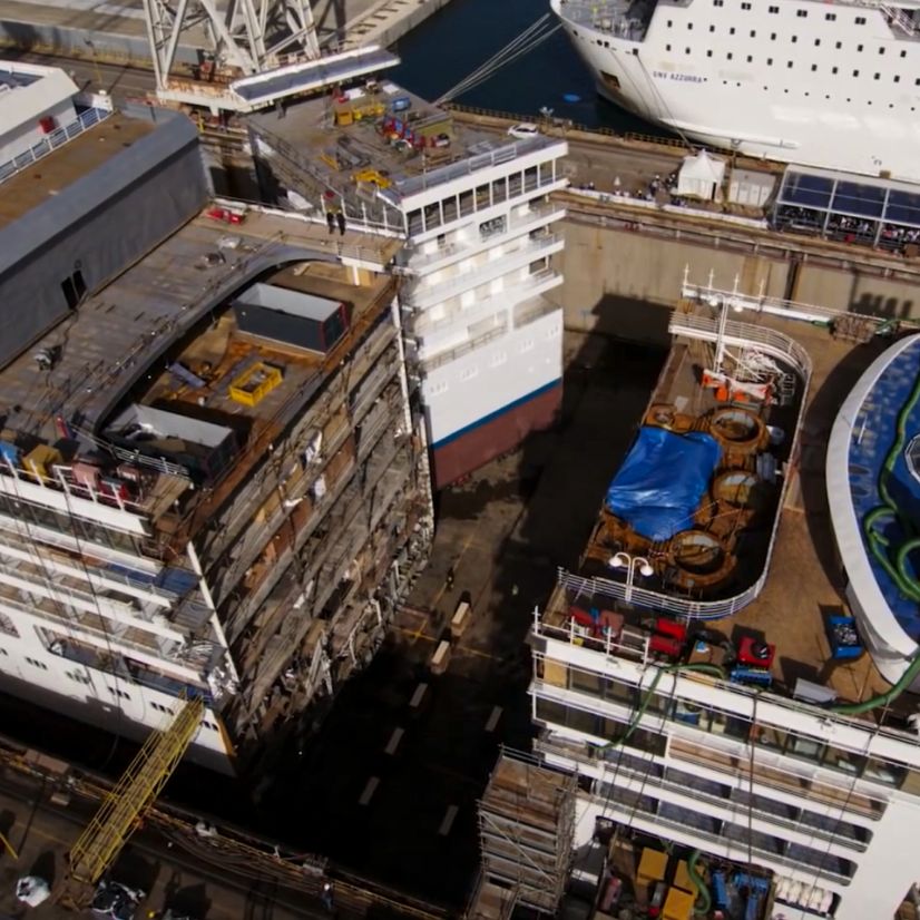
Sliding in an extra slice of cruise ship to lengthen it. (Credit: Silversea cruises)
The number of people going on cruises keeps rising year over year, with the number passengers carried increasing from just over 3.7 million in 1990 to well over 28 million in 2023. This has meant an increasing demand for more and also much larger cruise ships, which has led to an interesting phenomenon where it has become more economical to chop up an existing cruise ship and put in an extra slice to add many meters to each deck. This makes intuitively sense, as the segment added is fairly ‘dumb’, with no engine room, control systems, but mostly more rooms and cabins.
The current top-of-the-line cruise ship experience is exemplified by the Icon class that’s being constructed for the Royal Caribbean Group. The first in this line is the Icon of the Seas, which is the largest cruise ship in the world with a length of 364.75 meters and a gross tonnage of 248,663. All of this cost €1.86 billion and over two years of construction time, compared to around $80 million and a few months in the drydock. When combined with a scheduled maintenance period in the drydock, this ‘Jumboization’ process can be considered to be a great deal that gives existing cruise ships a new lease on life.
Extending a ship in this manner is fairly routine as well, with many ships beyond cruise ships seeing the torch before being split. A newly built segment is then slid in place, the metal segments are welded together, wires, tubing and more are spliced together, before the in and outside are ready for a new coat of paint that makes it seem like nothing ever happened to the ship.
Although not the first to try and build a DIY solar-powered remote control airplane, [ProjectAir]’s recent attempt is the most significant one in recent memory. It follows [rctestflight]’s multi-year saga with its v4 revision in 2019, as well as 2022’s rather big one by [Bearospace]. With so many examples to look at, building a solar-powered RC airplane in 2024 should be a snap, surely?
The first handicap was that [ProjectAir] is based in the UK, which means dealing with the famously sunny weather in those regions. The next issue was that the expensive, 20% efficient solar panels are exceedingly fragile, so the hope was that hot-gluing them to the foam of the airplane would keep them safe, even in the case of a crash. During the first test flights they quickly found that although the airplane few fairly well, the moment the sun vanished behind another cloud, the airplane would quite literally fall out of the sky, damaging some cells in the process.
For the final revision, a storage battery was picked, which got charged with an MPPT charger. The airplane itself was changed to be as low-drag as possible, with 60 photovoltaic (PV) cells stuck to its wings. This resulted in the somewhat spindly, swept wing, tail-less pusher design. After debugging a fun issue with EMI from the motor and the navigation module a test flight could be performed, which had the airplane autonomously keep a fixed course. That’s when everything went horribly wrong.
During the subsequent crash investigation, it was found that a total power loss occurred, due to the MPPT charger overcharging the battery, possibly due to a shared ground with the PV cells. Simultaneously, likely due to rushing the testing as bad weather was incoming, the backup battery on the controller was not installed, resulting in the airplane plummeting once primary power ran out. Fortunately, all of these are fixable issues, while providing a learning experience at the cost of an RC airplane and the PV cells that got destroyed in the crash.
Perhaps most importantly, this shows that even if much of building one’s own PV RC airplane in 2024 is just sticking off-the-shelf modules together, there’s no substitute for good engineering, not to mention assembly & pre-flight checklists.
Many have sought the holy grail of making commercial media both readable and copy-proof, especially once everyone began to copy those floppies. One of these attempts to make floppies copy-proof was Softguard’s Superlok. This in-depth look at this copy protection system by [GloriousCow] comes on the heels of a part 1 that covers Formaster’s Copy-Lock. Interestingly, Sierra switched from Copy-Lock to Superlok for their DOS version of games like King’s Quest, following the industry’s quest in search of this holy grail.
The way that Superlok works is that it loads a (hidden) executable called CPC.COM which proceeds to read the 128 byte key that is stored on a special track 6. With this key the game’s executable is decoded and fun can commence. Without a valid ‘Play’ disk containing the special track and CPC.COM executable all one is instead left with is a request by the game to ‘insert your ORIGINAL disk 1’.
Sierra’s King Quest v1.0 for DOS.
As one can see in the Norton Commander screenshot of a Sierra game disk, the hidden file is easily uncovered in any application that supports showing hidden files. However, CPC.COM couldn’t be executed directly; it needs to be executed from a memory buffer and passed the correct stack parameters. Sierra likely put in very little effort when implementing Softguard’s solution in their products, as Superlok supports changing the encryption key offset and other ways to make life hard for crackers.
Sierra was using version 2.3 of Superlok, but Softguard would also make a version 3.0. This is quite similar to 2.x, but has a gotcha in that it reads across the track index for the outer sector. This requires track wrapping to be implemented. Far from this kind of copy protection cracking being a recent thing, there was a thriving market for products that would circumvent these protections, all the way up to Central Point’s Copy II PC Option Board that would man-in-the-middle between the floppy disk drive and the CPU, intercepting data and render those copy protections pointless.
As for the fate of Softguard, by the end of the 1980s many of its customers were tiring of the cat-and-mouse game between crackers and Softguard, along with issues reported by legitimate users. Customers like Infographics Inc. dropped the Superlok protection by 1987 and by 1992 Softguard was out of business.
While plastics are very useful on their own, they can be much stronger when reinforced and mixed with a range of fibers. Not surprisingly, this includes the thermoplastic polymers which are commonly used with FDM 3D printing, such as polylactic acid (PLA) and polyamide (PA, also known as nylon). Although the most well-known fibers used for this purpose are probably glass fiber (GF) and carbon fiber (CF), these come with a range of issues, including their high abrasiveness when printing and potential carcinogenic properties in the case of carbon fiber.
So what other reinforcing fiber options are there? As it turns out, cellulose is one of these, along with basalt. The former has received a lot of attention currently, as the addition of cellulose and similar elements to thermopolymers such as PLA can create so-called biocomposites that create plastics without the brittleness of PLA, while also being made fully out of plant-based materials.
Regardless of the chosen composite, the goal is to enhance the properties of the base polymer matrix with the reinforcement material. Is cellulose the best material here?
Cellulose Nanofibers
Plastic objects created by fused deposition modeling (FDM) 3D printing are quite different from their injection-molding counterparts. In the case of FDM objects, the relatively poor layer adhesion and presence of voids means that 3D-printed PLA parts only have a fraction of the strength of the molded part, while also affecting the way that any fiber reinforcement can be integrated into the plastic. This latter aspect can also be observed with the commonly sold CF-containing FDM filaments, where small fragments of CF are used rather than long strands.
According to a study by Tushar Ambone et al. (2020) as published (PDF) in Polymer Engineering and Science, FDM-printed PLA has a 49% lower tensile strength and 41% lower modulus compared to compression molded PLA samples. The addition of a small amount of sisal-based cellulose nanofiber (CNF) at 1% by weight to the PLA subsequently improved these parameters by 84% and 63% respectively, with X-ray microtomography showing a reduction in voids compared to the plain PLA. Here the addition of CNF appears to significantly improve the crystallization of the PLA with corresponding improvement in its properties.
Fibers Everywhere
Incidentally a related study by Chuanchom Aumnate et al. (2021) as published in Cellulose used locally (India) sourced kenaf cellulose fibers to reinforce PLA, coming to similar results. This meshes well with the findings by Usha Kiran Sanivada et al. (2020) as published in Polymers, who mixed flax and jute fibers into PLA. Although since they used fairly long fibers in compression and injection molded samples a direct comparison with the FDM results in the Aumnate et al. study is somewhat complicated.
Meanwhile the use of basalt fibers (BF) is already quite well-established alongside glass fibers (GF) in insulation, where it replaced asbestos due to the latter’s rather unpleasant reputation. BF has some advantages over GF in composite materials, as per e.g. Li Yan et al. (2020) including better chemical stability and lower moisture absorption rates. As basalt is primarily composed of silicate, this does raise the specter of it being another potential cause of silicosis and related health risks.
With the primary health risk of mineral fibers like asbestos coming from the jagged, respirable fragments that these can create when damaged in some way, this is probably a very pertinent issue to consider before putting certain fibers quite literally everywhere.
A 2018 review by Seung-Hyun Park in Saf Health Work titled “Types and Health Hazards of Fibrous Materials Used as Asbestos Substitutes” provides a good overview of the relative risks of a range of asbestos-replacements, including BF (mineral wool) and cellulose. Here mineral wool fibers got rated as IARC Group 3 (insufficient evidence of carcinogenicity) except for the more biopersistent types (Group 2B, possibly carcinogenic), while cellulose is considered to be completely safe.
Finally, related to cellulose, there is also ongoing research on using lignin (present in plants next to cellulose as cell reinforcement) to improve the properties of PLA in combination with cellulose. An example is found in a 2021 study by Diana Gregor-Svetec et al. as published in Polymers. PLA composites created with lignin and surface-modified nanofibrillated (nanofiber) cellulose (NFC). A 2023 study by Sofia P. Makri et al. (also in Polymers) examined methods to improve the dispersion of the lignin nanoparticles. The benefit of lignin in a PLA/NFC composite appears to be in UV stabilization most of all, which should make objects FDM printed using this material last significantly longer when placed outside.
End Of Life
Another major question with plastic polymers is what happens with them once they inevitably end up discarded in the environment. There should be little doubt about what happens with cellulose and lignin in this case, as every day many tons of cellulose and lignin are happily devoured by countless microorganisms around the globe. This means that the only consideration for cellulose-reinforced plastics in an end-of-life scenario is that of the biodegradability of PLA and other base polymers one might use for the polymer composite.
Today, many PLA products end up discarded in landfills or polluting the environment, where PLA’s biodegradability is consistently shown to be poor, similar to other plastics, as it requires an industrial composting process involving microbial and hydrolytic treatments. Although incinerating PLA is not a terrible option due to its chemical composition, it is perhaps an ironic thought that the PLA in cellulose-reinforced PLA might actually be the most durable component in such a composite.
That said, if PLA is properly recycled or composted, it seems to pose few issues compared to other plastics, and any cellulose components would likely not interfere with the process, unlike CF-reinforced PLA, where incinerating it is probably the easiest option.
Do you print with hybrid or fiber-mixed plastics yet?
The European Space Agency (ESA) is showing 3D-printed metal parts made onboard the International Space Station using a printer and materials the agency sent earlier this year. While 3D printing onboard the ISS is nothing new, the printing of metal parts in space is an important advancement. The agency’s goals are to be able to produce more tools and spares in situ rather than having to rely on resupply missions. An ambitious idea being pitched is to use captured space debris as input as well, which would further decrease the ISS’s dependence on Earth and expensive cargo runs from the bottom of the gravity well.
The metal 3D printer in operation during testing on Earth prior to being installed on the ISS. (Credit: ESA)
The 180 kg 3D printer lives in the European Drawer Rack Mark II inside ESA’s Columbus module. Controllers on Earth managed the printing process after installation. The printer ran for about four hours a day, with each layer inspected before continuing. This means the printing process took days, but running the machine continuously would, of course, cut printing time significantly.
The printer uses stainless steel wire that is fed to the printing location, where a laser melts it. As the pool of molten metal moves away from the laser-heated spot, it solidifies like plastic does in a regular FDM printer. Of course, with the melting point of stainless steel being around 1400 °C, it runs a lot hotter and thus requires that the printer to be inside a completely sealed box, with the atmosphere inside vented into space and replaced with nitrogen prior to starting the printing process. The presence of oxygen would totally ruin the print.
We badly want a practical metal printer for home use, but, so far, they remain out of reach. When you do get them, you might consider that there are different design rules for metal-printed parts.
Although we generally assume that opacity is the normal look for animals like us humans, this factoid is only correct for as long as you maintain the dissimilar optical refraction indices of skin and the more aqueous underlying structures. What if you could change the refraction index of skin? If you could prevent the normal scattering at the interface, you could reveal the structures underneath, effectively rendering skin transparent. [Zihao Uo] and others demonstrate this in a paper published in Science.
The substance they used was the common food dye known as tartrazine, which also goes by the names of Yellow 5 and E102 when it is used in food (like Doritos), cosmetics, and drugs. By rubbing the tartrazine into the skin of mice, the researchers were able to observe underlying blood vessels and muscles. Simulations predicted that the dye would change the refraction index mismatch between lipids and water which normally causes the light scattering that creates the skin’s opaque appearance. With the dye rubbed into the skin, the effect worked to a depth of about 3 mm, which makes it useful for some research and possible medical applications, but not quite at the ‘jellyfish-transparency’ levels that some seem to have imagined at the news.
Researchers and medical personnel have long wished for this kind of in vivo tissue transparency. A 2019 review article by [Mikhail Inyushin] and colleagues in Molecules provides an overview of the many possible ways, both genetic and chemical, that you might see through skin. Tartrazine has a significant advantage: it is generally considered to be a harmless food dye. In addition, reversing the effect is as simple as washing the dye off.
Naturally, human skin will be trickier than that of mice due to the varying presence of melanin. So it will take more work to use this technique on people, but there are many mice and other common lab test critters who are breathing a deep sigh of relief as the scalpel can be put away for some types of studies.
Polypropylene (PP) is a thermoplastic that has a number of properties that sets it apart from other thermoplastics which see common use with 3D printing, including PLA, ABS and nylon (PA). Much like ABS (and the similar ASA), it is a pretty touchy material to print, especially on FDM printers. Over at the [All3DP] site [Nick Loth] provides a quick start guide for those who are interested in using PP with 3D printing, whether FDM, SLS or others.
A nice aspect of printing with PP is that it requires similar temperatures for the extruder (205 – 275 °C) and print bed (80 – 100 °C) as other common FDM filaments. As long as airflow can be controlled in the (enclosed) printer, issues with warping and cracking as the extruded filament cools should not occur. Unlike ABS and ASA which also require an enclosed, temperature-controlled printing space, PP has an advantage that printing with it does not produce carcinogenic fumes (styrene, acrylonitrile, etc.), but it does have the issue of absolutely not wanting to adhere to anything that is not PP. This is where the article provides some tips, such as the use of PP-based adhesive tape on the print bed, or the use of PP-based print plates.
As far as PP longevity and recyclability goes, it compares favorably with ABS and PA, meaning it’s quite resilient and stable, though susceptible to degradation from UV exposure without stabilizers. Recycling PP is fairly easy, though much like with polymers like PLA, the economics and logistics of recycling remain a challenge.
The Bluetooth SIG recently released the core specification for version 6.0 of Bluetooth. Compared to 5.x, it contains a number of changes and some new features, the most interesting probably being Channel Sounding. This builds upon existing features found in Bluetooth 5.x to determine the angle to, and direction of another device using Angle of Arrival (AoA) and Angle of Departure (AoD), but uses a new approach to much more precisely determine these parameters. as defined in the Technical Overview document for this feature.
In addition to this feature, there are also new ways to filter advertising packets, to reduce the number of packets to sift through (Decision-Based Advertising Filtering) and to filter out duplicate packets (Monitoring Advertisers). On a fundamental level, the Isochronous Adaptation Layer (ISOAL) received a new framing mode to reduce latency and increase reliability, alongside frame spacing now being negotiable and additional ways to exchange link layer information between devices.
As with any Bluetooth update, it will take a while before chipsets supporting it become widely available, and for the new features to be supported, but it gives a glimpse of what we can likely expect from Bluetooth-enabled devices in the future.
There’s currently a significant amount of confusion around the full extent of the GPIO hardware issue in the Raspberry Pi RP2350 microcontroller, with [Ian] over at [Dangerous Prototypes] of Bus Pirate fame mentioning that deliveries of the RP2350-based Bus Pirate 5XL and 6 have been put on hold while the issue is further being investigated. Recorded in the MCU’s datasheet as erratum RP2350-E9, it was originally reported as only being related to the use of internal pull-downs, but [Ian] has since demonstrated in the primary issue ticket on GitHub that the same soft latching behavior on GPIO pins occurs also without pull-downs enabled.
Ian from Dangerous Prototypes demonstrating the RP2350-E9 issue in a Bus Pirate prototype without pull-ups.
When we first reported on this hardware bug in the RP2350’s A2 (and likely preceding) stepping there was still a lot of confusion about what this issue meant, but so far we have seen the Bus Pirate delay and projects like [Agustín Gimenez Bernad]’s LogicAnalyzer have opted for taking the RP2350 port out back. There are also indications that the ADC and PIO peripherals are affected by this issue, with workarounds only partially able to circumvent the hardware issue.
In the case of the Bus Pirate a potential workaround is the addition of 4.7 kOhm external pull-downs, but at the cost of 0.7 mA continuous load on the GPIO when pulled high and part of that when pulled low. It’s an ugly hack, but at the very least it might save existing boards. It also shows how serious a bug this is.
Meanwhile there are lively discussions about the issue on the Raspberry Pi forums, both on the E9 erratum as well as the question of when there will be a new stepping. The official statement by Raspberry Pi is still that ‘they are investigating’. Presumably there will be a Bx stepping at some point, but for now it is clear that the RP2350’s A2 stepping is probably best avoided.
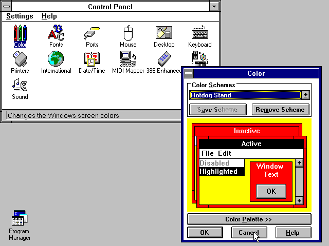
Once the nerve center of Windows operating systems, the Control Panel and its multitude of applets has its roots in the earliest versions of Windows. From here users could use these configuration applets to control and adjust just about anything in a friendly graphical environment. Despite the lack of any significant criticism from users and with many generations having grown up with its familiar dialogs, it has over the past years been gradually phased out by the monolithic Universal Windows Platform (UWP) based Settings app.
Whereas the Windows control panel features an overview of the various applets – each of which uses Win32 GUI elements like tabs to organize settings – the Settings app is more Web-like, with lots of touch-friendly whitespace, a single navigable menu, kilometers of settings to scroll through and absolutely no way to keep more than one view open at the same time.
Unsurprisingly, this change has not been met with a lot of enthusiasm by the average Windows user, and with Microsoft now officially recommending users migrate over to the Settings app, it seems that before long we may have to say farewell to what used to be an intrinsic part of the Windows operating system since its first iterations. Yet bizarrely, much of the Control Panel functionality doesn’t exist yet in the Settings app, and it remain an open question how much of it can be translated into the Settings app user experience (UX) paradigm at all.
Considering how unusual this kind of control panel used to be beyond quaint touch-centric platforms like Android and iOS, what is Microsoft’s goal here? Have discovered a UX secret that has eluded every other OS developer?
A Simple Concept
The Windows 3.1 Control Panel (1992). (Source: ToastyTech.com)
Settings which a user may want to tweak on their computer system range from hardware devices and networks to the display resolution and wallpaper, so it makes sense to put all of these configuration options within an easy to reach and use location. Generally this has meant something akin to a folder containing various clickable icons and accompanying text which together make clear what settings can be configured by opening it. In addition, the same setting dialogs can be accessed using context-sensitive menus, such as when right-clicking on the desktop.
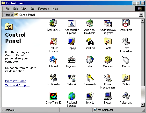
The Windows 98 Control Panel. (Source: ToastyTech.com)
It’s little wonder that for the longest time operating systems have settled for this approach, as it is intuitive, and individual items can have stylized icons that make it even more obvious what settings can be configured by clicking on it, such a keyboard, a mouse, a display, etc. As graphical fidelity increased, so did the styling of these icons, with MacOS, Windows, BeOS and the various desktop environments for OSs like the Linuxes and BSDs all developing their own highly skeuomorphic styles to make their UIs more intuitive and also more pleasant to look at. A good overview of the Windows Control Panel evolution can be found over at the Version Museum website.
The Windows XP Control Panel in ‘Classic’ view. (2001) (Source: suffieldacademy.org)
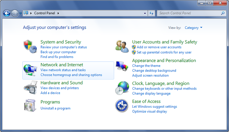
Coming from the still somewhat subdued style of Windows XP after years of Windows 9x and Windows NT/2000, Windows Vista and Windows 7 cranked this style up to eleven with the Windows Aero design language. This meant glass, color, translucency, depth and high-fidelity icons that made the function of the Control Panel’s individual entries more obvious than ever, creating a masterpiece that would be very hard to beat. The user was also given two different ways to view the Control Panel: the simplified category-based view, or the ‘classic’ view with all icons (and folders for e.g. Administrative Tools) visible in one view.
Windows 7 Control Panel (2009) in category view. (Source: techrepublic.com)
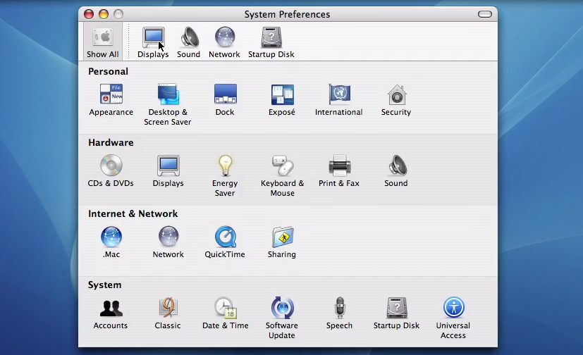
Meanwhile Apple did much the same thing, leaning heavily into their unique design language not only for its desktop, but ultimately also for its mobile offerings. Everything was pseudo-3D, with vivid colors adorning detailed renderings of various physical items and so on, creating a true feast for the eyes when taking in these lush UIs, with efficient access to settings via clearly marked tabs and similar UI elements.
The Mac OS X Panther System Preferences in 2003. (Source: Gadget Unity TV)
This way of organizing system settings was effectively replicated across a multitude of environments, with operating systems like Haiku (based on BeOS) and ReactOS (re-implementing Windows) retaining those classical elements of the original. A truly cross-platform, mostly intuitive experience was created, and Bliss truly came to the computing world.
Naturally, something so good had no right to keep existing, ergo it had to go.
The World Is Flat
The first to make the big change was Microsoft, with the release of Windows 8 and its Metro design language. This new visual style relied on simple shapes, with little to no adornments or distractions (i.e. more than a single color). Initially Microsoft also reckoned that Windows users wanted every window to be full-screen, and that hot edges and sides rather than a task bar and start menu was the way to go, as every single system running Windows 8 would obviously have a touch screen. Fortunately they did backtrack on this, but their attempt to redesign the Control Panel into something more Metro-like with the Settings app did persist, like an odd growth somewhere on a body part.
Windows 8’s PC Settings app (2012). (Source: softpedia.com)
Although the Control Panel remained in Windows 8 as well, the course had been set. Over time this small lump developed into the Settings app in Windows 10, by which time Metro had been renamed into the Microsoft Design Language (MDL), which got a recent tweak in what is now called the Fluent Design Language (FDL) for Windows 11.
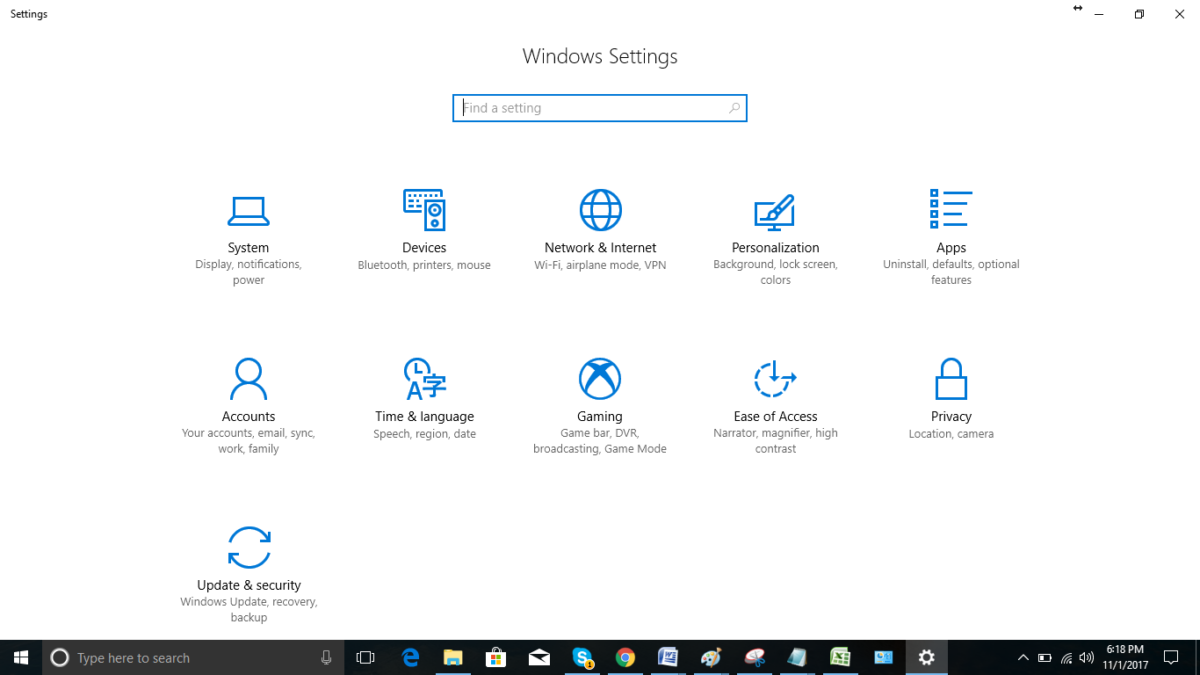
Central to this is the removal of almost all colors, the use of text labels over icons where possible (though simple monochrome icons are okay) and only rectangles with no decorations. This also meant no folder-centric model for settings but rather all the items put into a text-based menu on the left-hand side and an endless scroll-of-doom on the right side containing sparsely distributed settings.
This led to the absolutely beautifully dystopian Settings app as it exists in Windows 10:
The Settings app in Windows 10 back in ~2015. Hope you don’t like colors.
All of this came as skeuomorphic designs were suddenly considered ‘passé’, and the new hotness was so-called Flat Design. Google’s Material Design as developed in 2014 is another good example of this, with the characteristic ‘flat UI elements adrift in a void’ aesthetic that has now been adopted by Microsoft, and a few years ago by Apple as well starting in 2022 with MacOS Ventura’s System Settings (replacing System Preferences).
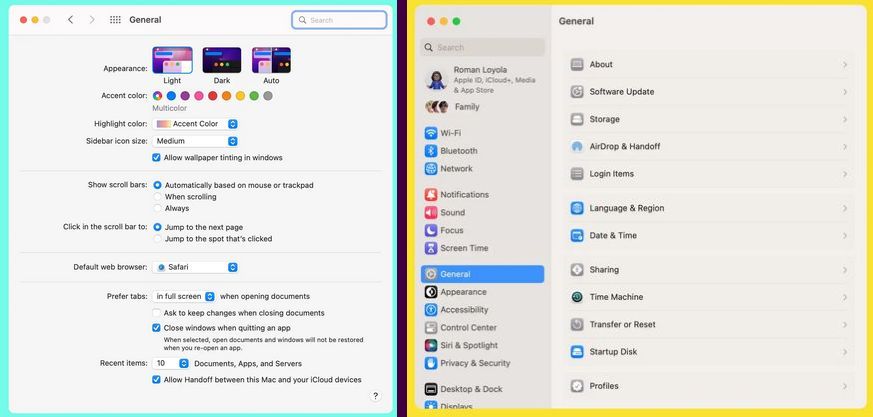
Monterey’s General system preferences (left) are different from Ventura’s General system settings (right). (Credit: MacWorld)
Rather than a tabbed interface to provide a clear overview, everything is now a blind hierarchy of menu items to scroll through and activate to access sub-, sub-sub-, and sub-sub-sub- items, and inevitably realize a few times that you’re in the wrong section. But rather than being able to click that other, correct tab, you now get to navigate back multiple views, one click at a time.
It isn’t just Windows and Apple either, but many of the big desktop environments like Gnome have also moved to this Flat Design Language. While various reasons have been provided for these changes, it’s undeniable that FDL makes a UI less intuitive (because there’s less useful visual information) and makes for a worse user experience (UX) with worse ergonomics as a result (because of the extra scrolling and clicking). This is especially obvious in the ‘independent applets’ versus ‘monolithic settings app’ comparison.
One-Track Mind
Imagine that you’re trying out a couple new wallpapers in Windows while keeping an eye on Windows Update’s latest shenanigans. You then need to quickly adjust the default audio device or another small adjustment unrelated to any of these other tasks. If you are using Windows 7 or earlier with the Control Panel applets, this is normal behavior and exceedingly common especially during hardware troubleshooting sessions.
If you’re using the Settings app, this is impossible, as only view can be active at a given time. You think you’re smart and right-click the desktop for ‘Personalize desktop’ so that the other Settings view stays intact? This is not how it works, as the Settings app is monolithic and now shifts to the newly selected view. Currently this is not too noticeable yet as many applets still exist in Windows 10 and 11, but as more and more of these are assimilated into the Settings app, such events will become more and more common.
It would seem that after decades of UI and UX evolution, we have now reached a definite point where UX is only getting worse, arguably around the release of Windows 8. With color banished, anything even remotely pseudo-3D frowned upon and UIs based around touch interfaces, there will soon be no difference between using a desktop PC, tablet or smartphone. Just in the worst way possible, as nobody has ever written about the amazing ergonomics and efficient UX of the latter two devices.
Perhaps our only hope may lie with the OSes and desktop environments that keep things real and stick to decades of proven UX design rather than give into Fad Driven Development.
Rest in peace, Windows Control Panel. We hope to see you again soon in ReactOS.
Recently Raspberry Pi released the 2GB version of the Raspberry Pi 5 with a new BCM2712 SoC featuring the D0 stepping. As expected, [Jeff Geerling] got his mitts on one of these boards and ran it through its paces, with positive results. Well, mostly positive results — as the Geekbench test took offence to the mere 2 GB of RAM on the board and consistently ran out of memory by the multi-core Photo Filter test, as feared when we originally reported on this new SBC. Although using swap is an option, this would not have made for a very realistic SoC benchmark, ergo [Jeff] resorted to using sysbenchinstead.
Naturally some overclocking was also performed, to truly push the SoC to its limits. This boosted the clock speed from 2.4 GHz all the way up to 3.5 GHz with the sysbench score increasing from 4155 to 6068. At 3.6 GHz the system wouldn’t boot any more, but [Jeff] figured that delidding the SoC could enable even faster speeds. This procedure also enabled taking a look at the bare D0 stepping die, revealing it to be 32.5% smaller than the previous C1 stepping on presumably the same 16 nm process.
Although 3.5 GHz turns out to be a hard limit for now, the power usage was interesting with idle power being 0.9 watts lower (at 2.4 W) for the D0 stepping and the power and temperatures under load also looked better than the C1 stepping. Even when taking the power savings of half the RAM versus the 4 GB version into account, the D0 stepping seems significantly more optimized. The main question now is when we can expect to see it appear on the 4 and 8 GB versions of the SBC, though the answer there is likely ‘when current C1 stocks run out’.
Although quantum processors exist today, they are still a long way off from becoming practical replacements for classical computers. This is due to many practical considerations, not the least of which are factors such as the need for cryogenic cooling and external noise affecting the system necessitating a level of error-correction which does not exist yet. To somewhat work around these limitations, IBM has now pitched the idea of a hybrid quantum-classical computer (marketed as ‘quantum-centric supercomputing’), which as the name suggests combines the strengths of both to create a classical system with what is effectively a quantum co-processor.
IBM readily admits that nobody has yet demonstrated quantum advantage, i.e. that a quantum computer is actually better at tasks than a classical computer, but they figure that by aiming for quantum utility (i.e. co-processor level), it could conceivably accelerate certain tasks for a classical computer much like how a graphics processing unit (GPU) is used to offload everything from rendering graphics to massively parallel computing tasks courtesy of its beefy vector processing capacity. IBM’s System Two is purported to demonstrate this when it releases.
What the outcome here will be is hard to say, as the referenced 2023 quantum utility demonstration paper involving an Ising model was repeatedly destroyed by classical computers and even trolled by a Commodore 64-based version. Thus, at the very least IBM’s new quantum utility focus ought to keep providing us with more popcorn moments like those, and maybe a usable quantum system will roll out by the 2030s if IBM’s projected timeline holds up.
Erratum RP2350-E9 in the RP2350 datasheet, detailing the issue.
The newly released RP2350 microcontroller has a confirmed new bug in the current A2 stepping, affecting GPIO pull-down behavior. Listed in the Raspberry Pi RP2350 datasheet as errata RP2350-E9, it involves a situation where a GPIO pin is configured as a pull-down with input buffer enabled. After this pin is then driven to Vdd (e.g. 3.3V) and then disconnected, it will stay at around 2.1 – 2.2 V for a Vdd of 3.3V. This issue was discovered by [Ian Lesnet] of [Dangerous Prototypes] while working on an early hardware design using this MCU.
The suggested workaround by Raspberry Pi is to enable the input buffer before a read, and disable it again immediately afterwards. Naturally, this is far from ideal workaround, and the solution that [Ian] picked was to add external pull-down resistors. Although this negates the benefits of internal pull-down resistors, it does fix the issue, albeit with a slightly increased board size and BOM part count.
As for the cause of the issue, Raspberry Pi engineer [Luke Wren] puts the blame on an external IP block vendor. With hindsight perhaps running some GPIO validation tests involving pull-up and pull-down configurations with and without input buffer set could have been useful, but we’re guessing they may be performed on future Pi chips. Maybe treating the RP2350 A0 stepping as an ‘engineering sample’ is a good idea for the time being, with A3 (or B0) being the one you may want to use in actual production.
In some ways this feels like déjà vu, as the Raspberry Pi 4 and previous SBCs had their own share of issues that perhaps might have been caught before production.
(Note: original text listed A0 as current stepping, which is incorrect. Text has been updated correspondingly)
DEC’s LAN Bridge 100 was a major milestone in the history of Ethernet which made it a viable option for the ever-growing LANs of yesteryear and today. Its history is also the topic of a recent video by [The Serial Port], in which [Mark] covers the development history of this device. We previously covered the LANBridge 100 Ethernet bridge and what it meant as Ethernet saw itself forced to scale from a shared medium (ether) to a star topology featuring network bridges and switches.
Featured in the video is also an interview with [John Reed], a field service network technician who worked at DEC from 1980 to 1998. He demonstrates what the world was like with early Ethernet, with thicknet coax (10BASE5) requiring a rather enjoyable way to crimp on connectors. Even with the relatively sluggish 10 Mbit of thicknet Ethernet, adding an Ethernet store and forward bridge in between two of these networks required significant amounts of processing power due to the sheer number of packets, but the beefy Motorola 68k CPU was up to the task.
To prevent issues with loops in the network, the spanning tree algorithm was developed and implemented, forming the foundations of the modern-day Ethernet LANs, as demonstrated by the basic LAN Bridge 100 unit that [Mark] fires up and which works fine in a modern-day LAN after its start-up procedure. Even if today’s Ethernet bridges and switches got smarter and more powerful, it all started with that first LAN Bridge.
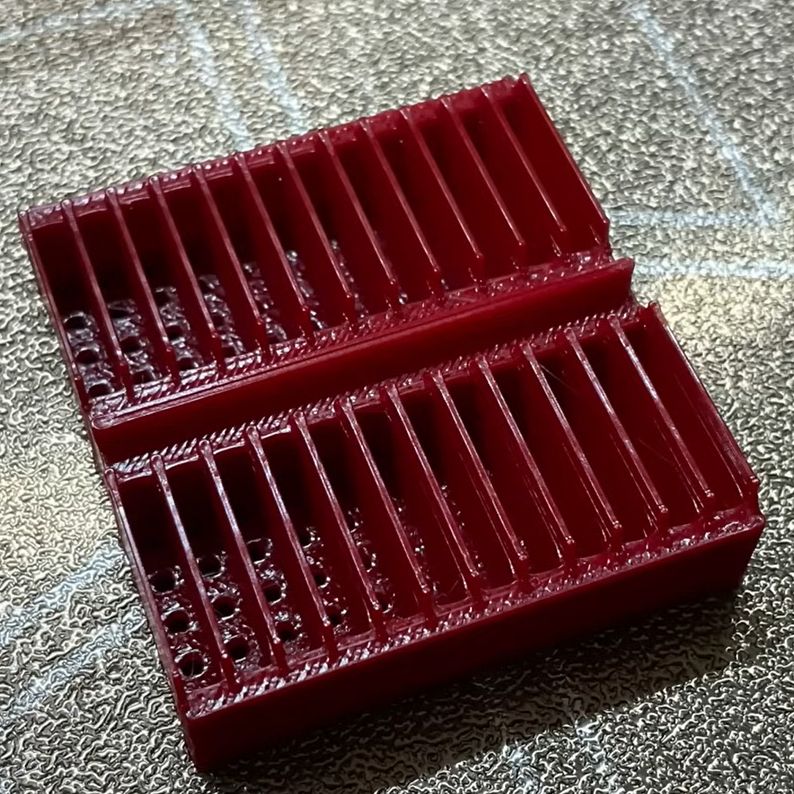
The printed breadboard cover as seen from the bottom. (Credit: CHEP, YouTube)
Does it make sense to make your own breadboards rather than purchasing off the shelf ones? As [Chuck Hellebuyck] notes in a recent video on DIY, 3D-printed breadboards, there’s a certain charm to making a breadboard exactly the size you need, which is hard to argue with. The inspiration came after seeing the metal breadboard spring clips on sale by [Kevin Santo Cappuccio], who also has a 3D printable breadboard shell project that they fit into. This means that you can take the CAD model (STEP file) and modify it to fit your specifications before printing it, which is what [Chuck] attempts in the video.
The models were exported from TinkerCAD to Bambu Lab Studio for printing on a Bambu Lab A1 Mini FDM printer. After a failed first print (which the A1 Mini, to its credit, did detect), a model was printed on a Creality K1 Max instead. Ultimately [Chuck] traced this back to the Bambu Lab Studio slicer failing to add the inner grid to the first layer, which the Creality slicer did add, caused by the ‘wall generator’ setting in the Bambu Lab slicer being set to ‘Classic’ rather than ‘Arachne,’ which can vary line width.
After this, the models printed fine and easily fit onto the spring clips that [Chuck] had soldered down on some prototyping board. A nice feature of these spring clips is that they have a bit of space underneath them where an SMD LED can fit, enabling functional (or just fancy) lighting effects when using a custom PCB underneath the contraption. As for whether it’s worth it depends on your needs. As [Chuck] demonstrates, it can be pretty convenient for a small breadboard on an add-on card (with or without custom lighting) like this, but it’s unlikely to replace generic breadboards for quick prototyping. We can, however, imagine a custom breadboard with mounting points for things like binding posts, switches, or potentiometers.
Lunar Module pilot Charles Duke saluting the US flag during Apollo 16. (Credit: NASA)
Imagine: you spent years training for a sojourn to the Moon, flew there on top of a Saturn V rocket as part of Apollo 16, to ultimately land on the lunar surface. You then spend the next few days on the surface, walking and skipping across the lunar regolith while setting up experiments and exploring per your mission assignments. Then, you pack everything up and blast off from the lunar surface to the orbiting command module before returning to Earth and a hero’s welcome. Then, decades later, you are told to your face that none of that ever happened. That’s the topic of a recent interview which [Jack Gordon] recently did with astronaut [Charles Duke].
None of these ‘arguments’ provided by the reality-denying crowd should be too shocking or feel new, as they range from the amount of fuel required to travel to the moon (solved by orbital mechanics) to the impossibility of lighting on the Moon (covered by everyone and their dog, including the Mythbusters in 2008).
Of course, these days, we have lunar orbiters (LRO and others) equipped with powerful cameras zoomed in on the lunar surface, which have photographed the Apollo landing sites with the experiments and footsteps still clearly visible. Like today’s crowd of spherical Earth deniers, skeptics will denounce anything that doesn’t fit their ill-conceived narrative as ‘faked’ for reasons that only exist in their fevered imaginations.
A common objection we’ve heard is that if we went to the moon back then, why haven’t we been back? The reason is obvious: politics. The STS (Shuttle) project sucked up all funding and the USSR collapsed. Only recently has there been a new kind of ‘space race’ in progress with nations like China. That doesn’t keep countless individuals from dreaming up lunar landing conspiracy theories to file away with their other truth nuggets, such as how microwaved and genetically engineered foods cause cancer, vaccines are another government conspiracy to control the population, and nuclear power plants can explode like nuclear bombs.
Perhaps the best takeaway is that even if we have not found intelligent life outside Earth yet, for at least a few years, intelligent life was the only kind on Earth’s Moon. We wish [Charles Duke] many happy returns, with maybe a casual return to the Moon in the near future as well, to frolic once more on the lunar surface.
Not that there hasn’t been a moon hoax, just not lately. If you want to watch the old Apollo video, it has been improved in recent years.
The history of consumer technology is littered with things that came and went. For whatever reason, consumers never really adopted the tech, and it eventually dies. Some of those concepts seem to persistently hang on, however, such as augmented reality (AR). Most recently, Apple launched its Vision Pro ‘mixed reality’ headset at an absolutely astounding price to a largely negative response and disappointing sale numbers. This impending market flop seems to now have made Meta (née Facebook) reconsider bringing a similar AR device to market.
To most, this news will come as little of a surprise, considering that Microsoft’s AR product (HoloLens) explicitly seeks out (government) niches with substantial budgets, and Google’s smart glasses have crashed and burned despite multiple market attempts. In a consumer market where virtual reality products are already desperately trying not to become another 3D display debacle, it would seem clear that amidst a lot of this sci-fi adjacent ‘cool technology,’ there are a lot of executives and marketing critters who seem to forego the basic question: ‘why would anyone use this?’
In the case of the Apple Vision Pro, the current debate is if augmented reality and spatial computing have any future at all, even as work on a Vision Pro 2 has been suspended. Meanwhile, Meta has decided to keep plugging away on its next VR headset (the predictably named Quest 4), as the VR consumer market so far is relatively healthy for a consumer product with limited mass-consumer appeal but with potential new use cases beyond games.
The fake AliExpress-sourced IRFP460 MOSFETs (Credit: Learn Electronics Repair, YouTube)
These days, it’s super-easy to jump onto the World Wide Web to find purported replacement parts using nothing but the part identifier, whether it’s from a reputable source like Digikey or Mouser or from more general digital fleamarkets like eBay and AliExpress. It’s hardly a secret that many of the parts you can buy online via fleamarkets are not genuine. That is, the printed details on the package do not match the actual die inside. After AliExpress-sourced MOSFETs blew in a power supply repair by [Learn Electronics Repair], he first tried to give the MOSFETs the benefit of the doubt. Using an incandescent lightbulb as a current limiter, he analyzed the entire PSU circuit before putting the blame on the MOSFETs (IRFP460) and ordering new ones from LCSC.
Buying from a distributor instead of a marketplace means you can be sure the parts are from the manufacturer. This means that when a part says it is a MOSFET with specific parameters, it almost certainly is. A quick component tester session showed the gate threshold of the LCSC-sourced MOSFETs to be around 3.36V, while that of the AliExpress ‘IRFP460’ parts was a hair above 1.8V, giving a solid clue that whatever is inside the AliExpress-sourced MOSFETs is not what the package says it should be.
Unsurprisingly, after fitting the PSU with the two LCSC-sourced MOSFETs, there was no more magic smoke, and the PSU now works. The lesson here is to be careful buying parts of unknown provenance unless you like magic smoke and chasing weird bugs.