Who knows what you’ll find in a second-hand shop? [Zeal] found some old keyboards made to fit early Alcatel phones from the year 2000 or so. They looked good but, of course, had no documentation. He’s made two videos about his adventure, and you can see them below.
The connector was a cellphone-style phone jack that must carry power and some sort of serial data. Inside, there wasn’t much other than a major chip and a membrane keyboard. There were a few small support chips and components, too.
This is a natural job for a logic analyzer. Sure enough, pressing a key showed some output on the logic analyzer. The device only outputs data, and so, in part 2, [Zeal] adds it to his single-board Z-80 computer.
It makes a cute package, but it did take some level shifting to get the 5V logic to play nice with the lower-voltage keyboard. He used a processor to provide protocol translation, although it looks like you could have easily handled the whole thing in the host computer software if you had wanted to do so.
Truthfully, there isn’t much chance you are going to find this exact keyboard. However, the process of opening a strange device and reverse engineering what it is all about is classic.
Don’t have a logic analyzer? A scope might have been usable for this, but you can also build one for very little these days. Using a PS/2 keyboard isn’t really easier, by the way, it is just well-documented.
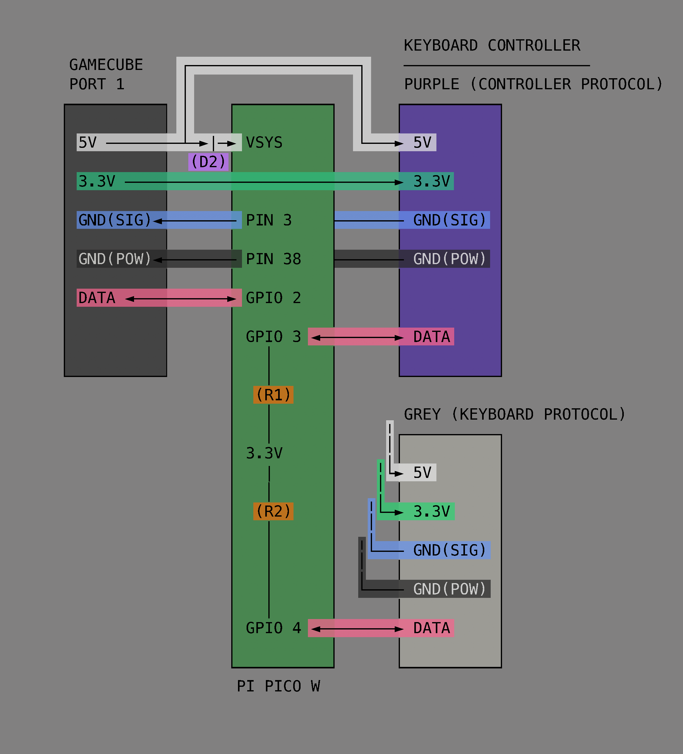
This project began simply enough but got very complicated in short order. Initially the goal was to get the GameCube keyboard controller integrated with the game Animal Crossing. The GameCube keyboard controller is a genuine part manufactured and sold by Nintendo but the game Animal Crossing isn’t compatible with this controller. Rather, Animal Crossing has an on-screen keyboard which players can use with a standard controller. [Hunter] found this frustrating to use so he created an adapter which would intercept the keyboard controller protocol and replace it with equivalent “keypresses” from an emulated standard controller.
In this project [Hunter] intercepts the controller protocol and the keyboard protocol with a Raspberry Pi Pico and then forwards them along to an attached GameCube by emulating a standard controller from the Pico. Having got that to work [Hunter] then went on to add a bunch of extra features.
First he designed and 3D-printed a new set of keycaps to match the symbols available in the in-game character set and added support for those. Then he made a keyboard mode for entering musical tunes in the game. Then he integrated a database of cheat codes to unlock most special items available in the game. Then he made it possible to import images (in low-resolution, 32×32 pixels) into the game. Then he made it possible to play (low-resolution) videos in the game. And finally he implemented a game of Snake, in-game! Very cool.
If you already own a GameCube and keyboard controller (or if you wanted to get them) this project would be good fun and doesn’t demand too much extra hardware. Just a Raspberry Pi Pico, two GameCube controller cables, two resistors, and a Schottky diode. And if you’re interested in Animal Crossing you might enjoy getting it to boot Linux!
Thanks very much to [Hunter] for writing in to let us know about this project. Have your own project? Let us know on the tipsline!
A lot of people complain that driving across the United States is boring. Having done the coast-to-coast trip seven times now, I can’t agree. Sure, the stretches through the Corn Belt get a little monotonous, but for someone like me who wants to know how everything works, even endless agriculture is fascinating; I love me some center-pivot irrigation.
One thing that has always attracted my attention while on these long road trips is the weigh stations that pop up along the way, particularly when you transition from one state to another. Maybe it’s just getting a chance to look at something other than wheat, but weigh stations are interesting in their own right because of everything that’s going on in these massive roadside plazas. Gone are the days of a simple pull-off with a mechanical scale that was closed far more often than it was open. Today’s weigh stations are critical infrastructure installations that are bristling with sensors to provide a multi-modal insight into the state of the trucks — and drivers — plying our increasingly crowded highways.
All About the Axles
Before diving into the nuts and bolts of weigh stations, it might be helpful to discuss the rationale behind infrastructure whose main function, at least to the casual observer, seems to be making the truck driver’s job even more challenging, not to mention less profitable. We’ve all probably sped by long lines of semi trucks queued up for the scales alongside a highway, pitying the poor drivers and wondering if the whole endeavor is worth the diesel being wasted.
The answer to that question boils down to one word: axles. In the United States, the maximum legal gross vehicle weight (GVW) for a fully loaded semi truck is typically 40 tons, although permits are issued for overweight vehicles. The typical “18-wheeler” will distribute that load over five axles, which means each axle transmits 16,000 pounds of force into the pavement, assuming an even distribution of weight across the length of the vehicle. Studies conducted in the early 1960s revealed that heavier trucks caused more damage to roadways than lighter passenger vehicles, and that the increase in damage is proportional to the fourth power of axle weight. So, keeping a close eye on truck weights is critical to protecting the highways.
Just how much damage trucks can cause to pavement is pretty alarming. Each axle of a truck creates a compression wave as it rolls along the pavement, as much as a few millimeters deep, depending on road construction and loads. The relentless cycle of compression and expansion results in pavement fatigue and cracks, which let water into the interior of the roadway. In cold weather, freeze-thaw cycles exert tremendous forces on the pavement that can tear it apart in short order. The greater the load on the truck, the more stress it puts on the roadway and the faster it wears out.
The other, perhaps more obvious reason to monitor axles passing over a highway is that they’re critical to truck safety. A truck’s axles have to support huge loads in a dynamic environment, and every component mounted to each axle, including springs, brakes, and wheels, is subject to huge forces that can lead to wear and catastrophic failure. Complete failure of an axle isn’t uncommon, and a driver can be completely unaware that a wheel has detached from a trailer and become an unguided missile bouncing down the highway. Regular inspections of the running gear on trucks and trailers are critical to avoiding these potentially catastrophic occurrences.
Ways to Weigh
The first thing you’ll likely notice when driving past one of the approximately 700 official weigh stations lining the US Interstate highway system is how much space they take up. In contrast to the relatively modest weigh stations of the past, modern weigh stations take up a lot of real estate. Most weigh stations are optimized to get the greatest number of trucks processed as quickly as possible, which means constructing multiple lanes of approach to the scale house, along with lanes that can be used by exempt vehicles to bypass inspection, and turnout lanes and parking areas for closer inspection of select vehicles.
In addition to the physical footprint of the weigh station proper, supporting infrastructure can often be seen miles in advance. Fixed signs are usually the first indication that you’re getting near a weigh station, along with electronic signboards that can be changed remotely to indicate if the weigh station is open or closed. Signs give drivers time to figure out if they need to stop at the weigh station, and to begin the process of getting into the proper lane to negotiate the exit. Most weigh stations also have a net of sensors and cameras mounted to poles and overhead structures well before the weigh station exit. These are monitored by officers in the station to spot any trucks that are trying to avoid inspections.
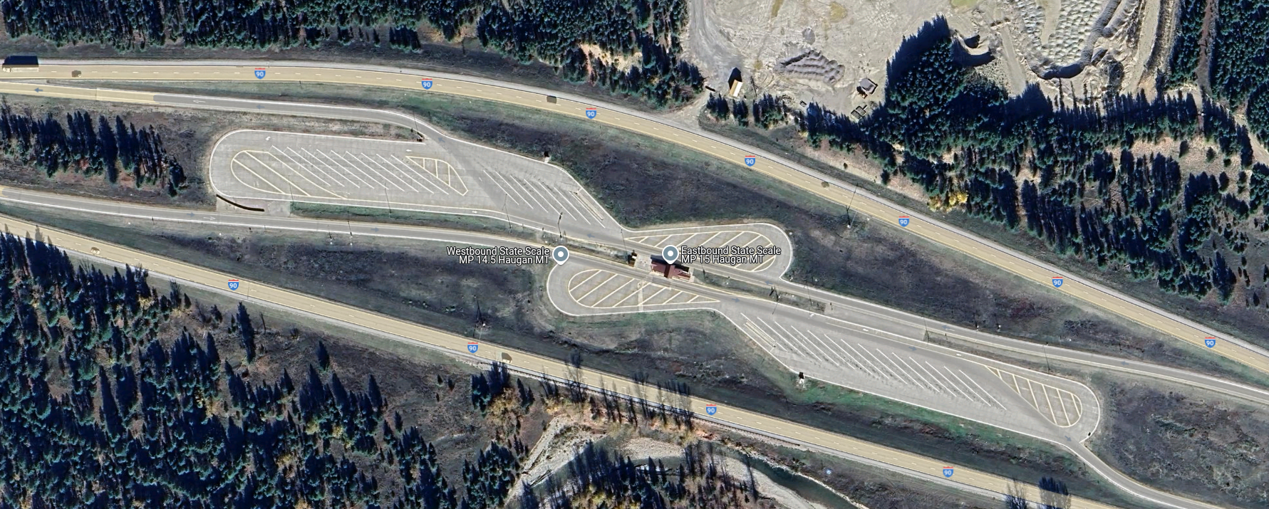
Overhead view of a median weigh station on I-90 in Haugan, Montana. Traffic from both eastbound and westbound lanes uses left exits to access the scales in the center. There are ample turnouts for parking trucks that fail one test or another. Source: Google Maps.
Most weigh stations in the US are located off the right side of the highway, as left-hand exit ramps are generally more dangerous than right exits. Still, a single weigh station located in the median of the highway can serve traffic from both directions, so the extra risk of accidents from exiting the highway to the left is often outweighed by the savings of not having to build two separate facilities. Either way, the main feature of a weigh station is the scale house, a building with large windows that offer a commanding view of the entire plaza as well as an up-close look at the trucks passing over the scales embedded in the pavement directly adjacent to the structure.
Scales at a weigh station are generally of two types: static scales, and weigh-in-motion (WIM) systems. A static scale is a large platform, called a weighbridge, set into a pit in the inspection lane, with the surface flush with the roadway. The platform floats within the pit, supported by a set of cantilevers that transmit the force exerted by the truck to electronic load cells. The signal from the load cells is cleaned up by signal conditioners before going to analog-to-digital converters and being summed and dampened by a scale controller in the scale house.
The weighbridge on a static scale is usually long enough to accommodate an entire semi tractor and trailer, which accurately weighs the entire vehicle in one measurement. The disadvantage is that the entire truck has to come to a complete stop on the weighbridge to take a measurement. Add in the time it takes for the induced motion of the weighbridge to settle, along with the time needed for the driver to make a slow approach to the scale, and each measurement can add up to significant delays for truckers.
Weigh-in-motion sensor. WIM systems measure the force exerted by each axle and calculate a total gross vehicle weight (GVW) for the truck while it passes over the sensor. The spacing between axles is also measured to ensure compliance with state laws. Source: Central Carolina Scales, Inc.
To avoid these issues, weigh-in-motion systems are often used. WIM systems use much the same equipment as the weighbridge on a static scale, although they tend to use piezoelectric sensors rather than traditional strain-gauge load cells, and usually have a platform that’s only big enough to have one axle bear on it at a time. A truck using a WIM scale remains in motion while the force exerted by each axle is measured, allowing the controller to come up with a final GVW as well as weights for each axle. While some WIM systems can measure the weight of a vehicle at highway speed, most weigh stations require trucks to keep their speed pretty slow, under five miles per hour. This is obviously for everyone’s safety, and even though the somewhat stately procession of trucks through a WIM can still plug traffic up, keeping trucks from having to come to a complete stop and set their brakes greatly increases weigh station throughput.
Another advantage of WIM systems is that the spacing between axles can be measured. The speed of the truck through the scale can be measured, usually using a pair of inductive loops embedded in the roadway around the WIM sensors. Knowing the vehicle’s speed through the scale allows the scale controller to calculate the distance between axles. Some states strictly regulate the distance between a trailer’s kingpin, which is where it attaches to the tractor, and the trailer’s first axle. Trailers that are not in compliance can be flagged and directed to a parking area to await a service truck to come by to adjust the spacing of the trailer bogie.
Keep It Moving, Buddy
A PrePass transponder reader and antenna over Interstate 10 near Pearlington, Mississippi. Trucks can bypass a weigh station if their in-cab transponder identifies them as certified. Source: Tony Webster, CC BY-SA 2.0.
Despite the increased throughput of WIM scales, there are often too many trucks trying to use a weigh station at peak times. To reduce congestion further, some states participate in automatic bypass systems. These systems, generically known as PrePass for the specific brand with the greatest market penetration, use in-cab transponders that are interrogated by transmitters mounted over the roadway well in advance of the weigh station. The transponder code is sent to PrePass for authentication, and if the truck ID comes back to a company that has gone through the PrePass certification process, a signal is sent to the transponder telling the driver to bypass the weigh station. The transponder lights a green LED in this case, which stays lit for about 15 minutes, just in case the driver gets stopped by an overzealous trooper who mistakes the truck for a scofflaw.
PrePass transponders are just one aspect of an entire suite of automatic vehicle identification (AVI) systems used in the typical modern weigh station. Most weigh stations are positively bristling with cameras, some of which are dedicated to automatic license plate recognition. These are integrated into the scale controller system and serve to associate WIM data with a specific truck, so violations can be flagged. They also help with the enforcement of traffic laws, as well as locating human traffickers, an increasingly common problem. Weigh stations also often have laser scanners mounted on bridges over the approach lanes to detect unpermitted oversized loads. Image analysis systems are also used to verify the presence and proper operation of required equipment, such a mirrors, lights, and mudflaps. Some weigh stations also have systems that can interrogate the electronic logging device inside the cab to verify that the driver isn’t in violation of hours of service laws, which dictate how long a driver can be on the road before taking breaks.
Sensors Galore
IR cameras watch for heat issues on trucks at a Kentucky weigh station. Heat signatures can be used to detect bad tires, stuck brakes, exhaust problems, and even illicit cargo. Source: Trucking Life with Shawn
Another set of sensors often found in the outer reaches of the weigh station plaza is related to the mechanical status of the truck. Infrared cameras are often used to scan for excessive heat being emitted by an axle, often a sign of worn or damaged brakes. The status of a truck’s tires can also be monitored thanks to Tire Anomaly and Classification Systems (TACS), which use in-road sensors that can analyze the contact patch of each tire while the vehicle is in motion. TACS can detect flat tires, over- and under-inflated tires, tires that are completely missing from an axle, or even mismatched tires. Any of these anomalies can cause a tire to quickly wear out and potentially self-destruct at highway speeds, resulting in catastrophic damage to surrounding traffic.
Trucks with problems are diverted by overhead signboards and direction arrows to inspection lanes. There, trained truck inspectors will closely examine the flagged problem and verify the violation. If the problem is relatively minor, like a tire inflation problem, the driver might be able to fix the issue and get back on the road quickly. Trucks that can’t be made safe immediately might have to wait for mobile service units to come fix the problem, or possibly even be taken off the road completely. Only after the vehicle is rendered road-worthy again can you keep on trucking.
It’s an inconvenient fact that most of Earth’s largesse of useful minerals is locked up in, under, and around a lot of rock. Our little world condensed out of the remnants of stars whose death throes cooked up almost every element in the periodic table, and in the intervening billions of years, those elements have sorted themselves out into deposits that range from the easily accessed, lying-about-on-the-ground types to those buried deep in the crust, or worse yet, those that are distributed so sparsely within a mineral matrix that it takes harvesting megatonnes of material to find just a few kilos of the stuff.
Whatever the substance of our desires, and no matter how it is associated with the rocks and minerals below our feet, almost every mining and refining effort starts with wresting vast quantities of rock from the Earth’s crust. And the easiest, cheapest, and fastest way to do that most often involves blasting. In a very real way, explosives make the world work, for without them, the minerals we need to do almost anything would be prohibitively expensive to produce, if it were possible at all. And understanding the chemistry, physics, and engineering behind blasting operations is key to understanding almost everything about Mining and Refining.
First, We Drill
For almost all of the time that we’ve been mining minerals, making big rocks into smaller rocks has been the work of strong backs and arms supplemented by the mechanical advantage of tools like picks, pry bars, and shovels. The historical record shows that early miners tried to reduce this effort with clever applications of low-energy physics, such as jamming wooden plugs into holes in the rocks and soaking them with liquid to swell the wood and exert enough force to fracture the rock, or by heating the rock with bonfires and then flooding with cold water to create thermal stress fractures. These methods, while effective, only traded effort for time, and only worked for certain types of rock.
Mining productivity got a much-needed boost in 1627 with the first recorded use of gunpowder for blasting at a gold mine in what is now Slovakia. Boreholes were stuffed with powder that was ignited by a fuse made from a powder-filled reed. The result was a pile of rubble that would have taken weeks to produce by hand, and while the speed with which the explosion achieved that result was probably much welcomed by the miners, in reality, it only shifted their efforts to drilling the boreholes, which generally took a five-man crew using sledgehammers and striker bars to pound deep holes into the rock. Replacing that manual effort with mechanical drilling was the next big advance, but it would have to wait until the Industrial Revolution harnessed the power of steam to run drills capable of boring deep holes in rock quickly and with much smaller crews.
The basic principles of rock drilling developed in the 19th century, such as rapidly spinning a hardened steel bit while exerting tremendous down-pressure and high-impulse percussion, remain applicable today, although with advancements like synthetic diamond tooling and better methods of power transmission. Modern drills for open-cast mining fall into two broad categories: overburden drills, which typically drill straight down or at a slight angle to vertical and can drill large-diameter holes over 100 meters deep, and quarry drills, which are smaller and more maneuverable rigs that can drill at any angle, even horizontally. Most drill rigs are track-driven for greater mobility over rubble-strewn surfaces, and are equipped with soundproofed, air-conditioned cabs with safety cages to protect the operator. Automation is a big part of modern rigs, with automatic leveling systems, tool changers that can select the proper bit for the rock type, and fully automated drill chain handling, including addition of drill rod to push the bit deeper into the rock. Many drill rigs even have semi-autonomous operation, where a single operator can control a fleet of rigs from a single remote control console.
Proper Prior Planning
While the use of explosives seems brutally chaotic and indiscriminate, it’s really the exact opposite. Each of the so-called “shots” in a blasting operation is a carefully controlled, highly engineered event designed to move material in a specific direction with the desired degree of fracturing, all while ensuring the safety of the miners and the facility.
To accomplish this, a blasting plan is put together by a mining engineer. The blasting plan takes into account the mechanical characteristics of the rock, the location and direction of any pre-existing fractures or faults, and proximity to any structures or hazards. Engineers also need to account for the equipment used for mucking, which is the process of removing blasted material for further processing. For instance, a wheeled loader operating on the same level, or bench, that the blasting took place on needs a different size and shape of rubble pile than an excavator or dragline operating from the bench above. The capabilities of the rock crushing machinery that’s going to be used to process the rubble also have to be accounted for in the blasting plan.
Most blasting plans define a matrix of drill holes with very specific spacing, generally with long rows and short columns. The drill plan specifies the diameter of each hole along with its depth, which usually goes a little beyond the distance to the next bench down. The mining engineer also specifies a stem height for the hole, which leaves room on top of the explosives to backfill the hole with drill tailings or gravel.
Prills and Oil
Once the drill holes are complete and inspected, charging the holes with explosives can begin. The type of blasting agents to be used is determined by the blasting plan, but in most cases, the agent of choice is ANFO, or ammonium nitrate and fuel oil. The ammonium nitrate, which contains 60% oxygen by weight, serves as an oxidizer for the combustion of the long-chain alkanes in the fuel oil. The ideal mix is 94% ammonium nitrate to 6% fuel oil.
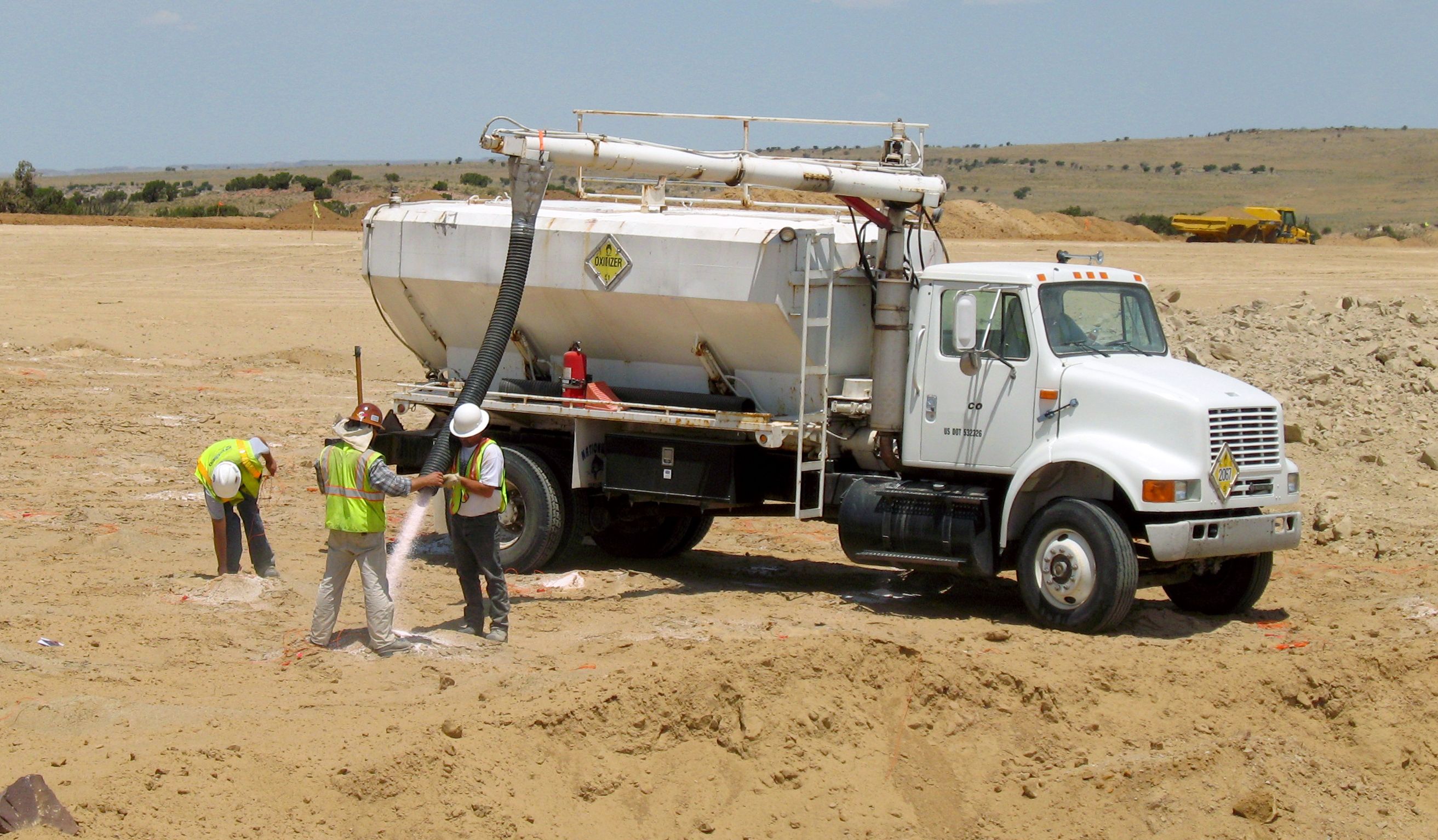
Filling holes with ammonium nitrate at a blasting site. Hopper trucks like this are often used to carry prilled ammonium nitrate. Some trucks also have a tank for the fuel oil that’s added to the ammonium nitrate to make ANFO. Credit: Old Bear Photo, via Adobe Stock.
How the ANFO is added to the hole depends on conditions. For holes where groundwater is not a problem, ammonium nitrate in the form of small porous beads or prills, is poured down the hole and lightly tamped to remove any voids or air spaces before the correct amount of fuel oil is added. For wet conditions, an ammonium nitrate emulsion will be used instead. This is just a solution of ammonium nitrate in water with emulsifiers added to allow the fuel oil to mix with the oxidizer.
ANFO is classified as a tertiary explosive, meaning it is insensitive to shock and requires a booster to detonate. The booster charge is generally a secondary explosive such as PETN, or pentaerythritol tetranitrate, a powerful explosive that’s chemically similar to nitroglycerine but is much more stable. PETN comes in a number of forms, with cardboard cylinders like oversized fireworks or a PETN-laced gel stuffed into a plastic tube that looks like a sausage being the most common.
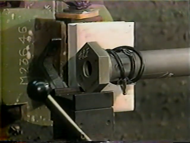
Electrically operated blasting caps marked with their built-in 425 ms delay. These will easily blow your hand clean off. Source: Timo Halén, CC BY-SA 2.5.
Being a secondary explosive, the booster charge needs a fairly strong shock to detonate. This shock is provided by a blasting cap or detonator, which is a small, multi-stage pyrotechnic device. These are generally in the form of a small brass or copper tube filled with a layer of primary explosive such as lead azide or fulminate of mercury, along with a small amount of secondary explosive such as PETN. The primary charge is in physical contact with an initiator of some sort, either a bridge wire in the case of electrically initiated detonators, or more commonly, a shock tube. Shock tubes are thin-walled plastic tubing with a layer of reactive explosive powder on the inner wall. The explosive powder is engineered to detonate down the tube at around 2,000 m/s, carrying a shock wave into the detonator at a known rate, which makes propagation delays easy to calculate.
Timing is critical to the blasting plan. If the explosives in each hole were to all detonate at the same time, there wouldn’t be anywhere for the displaced material to go. To prevent that, mining engineers build delays into the blasting plan so that some charges, typically the ones closest to the free face of the bench, go off a fraction of a second before the charges behind them, freeing up space for the displaced material to move into. Delays are either built into the initiator as a layer of pyrotechnic material that burns at a known rate between the initiator and the primary charge, or by using surface delays, which are devices with fixed delays that connect the initiator down the hole to the rest of the charges that will make up the shot. Lately, electronic detonators have been introduced, which have microcontrollers built in. These detonators are addressable and can have a specific delay programmed in the field, making it easier to program the delays needed for the entire shot. Electronic detonators also require a specific code to be transmitted to detonate, which reduces the chance of injury or misuse that lost or stolen electrical blasting caps present. This was enough of a problem that a series of public service films on the dangers of playing with blasting caps appeared regularly from the 1950s through the 1970s.
“Fire in the Hole!”
When all the holes are charged and properly stemmed, the blasting crew makes the final connections on the surface. Connections can be made with wires for electrical and electronic detonators, or with shock tubes for non-electric detonators. Sometimes, detonating cord is used to make the surface connections between holes. Det cord is similar to shock tube but generally looks like woven nylon cord. It also detonates at a much faster rate (6,500 m/s) than shock tube thanks to being filled with PETN or a similar high-velocity explosive.
Once the final connections to the blasting controller are made and tested, the area is secured with all personnel and equipment removed. A series of increasingly urgent warnings are sounded on sirens or horns as the blast approaches, to alert personnel to the danger. The blaster initiates the shot at the controller, which sends the signal down trunklines and into any surface delays before being transmitted to the detonators via their downlines. The relatively weak shock wave from the detonator propagates into the booster charge, which imparts enough energy into the ANFO to start detonation of the main charge.
The ANFO rapidly decomposes into a mixture of hot gases, including carbon dioxide, nitrogen, and water vapor. The shock wave pulverizes the rock surrounding the borehole and rapidly propagates into the surrounding rock, exerting tremendous compressive force. The shock wave continues to propagate until it meets a natural crack or the interface between rock and air at the free face of the shot. These impedance discontinuities reflect the compressive wave and turn it into a tensile wave, and since rock is generally much weaker in tension than compression, this is where the real destruction begins.
The reflected tensile forces break the rock along natural or newly formed cracks, creating voids that are filled with the rapidly expanding gases from the burning ANFO. The gases force these cracks apart, providing the heave needed to move rock fragments into the voids created by the initial shock wave. The shot progresses at the set delay intervals between holes, with the initial shock from new explosions creating more fractures deeper into the rock face and more expanding gas to move the fragments into the space created by earlier explosions. Depending on how many holes are in the shot and how long the delays are, the entire thing can be over in just a few seconds, or it could go on for quite some time, as it does in this world-record blast at a coal mine in Queensland in 2019, which used 3,899 boreholes packed with 2,194 tonnes of ANFO to move 4.7 million cubic meters of material in just 16 seconds.
There’s still much for the blasting crew to do once the shot is done. As the dust settles, safety crews use monitoring equipment to ensure any hazardous blasting gases have dispersed before sending in crews to look for any misfires. Misfires can result in a reshoot, where crews hook up a fresh initiator and try to detonate the booster charge again. If the charge won’t fire, it can be carefully extracted from the rubble pile with non-sparking tools and soaked in water to inactivate it.
Hold onto your hats, everyone — there’s stunning news afoot. It’s hard to believe, but it looks like over-reliance on chatbots to do your homework can turn your brain into pudding. At least that seems to be the conclusion of a preprint paper out of the MIT Media Lab, which looked at 54 adults between the ages of 18 and 39, who were tasked with writing a series of essays. They divided participants into three groups — one that used ChatGPT to help write the essays, one that was limited to using only Google search, and one that had to do everything the old-fashioned way. They recorded the brain activity of writers using EEG, in order to get an idea of brain engagement with the task. The brain-only group had the greatest engagement, which stayed consistently high throughout the series, while the ChatGPT group had the least. More alarmingly, the engagement for the chatbot group went down even further with each essay written. The ChatGPT group produced essays that were very similar between writers and were judged “soulless” by two English teachers. Go figure.
The most interesting finding, though, was when 18 participants from the chatbot and brain-only groups were asked to rewrite one of their earlier essays, with the added twist that the chatbot group had to do it all by themselves, while the brainiacs got to use ChatGPT. The EEGs showed that the first group struggled with the task, presumably because they failed to form any deep memory of their previous work thanks to over-reliance on ChatGPT. The brain-only folks, however, did well at the task and showed signs of activity across all EEG bands. That fits well with our experience with chatbots, which we use to help retrieve specific facts and figures while writing articles, especially ones we know we’ve seen during our initial scan of the literature but can’t find later.
Does anyone remember Elektro? We sure do, although not from personal experience, since the seven-foot-tall automaton built by Westinghouse for the World’s Fair in New York City in 1939 significantly predates our appearance on the planet. But still, the golden-skinned robot that made its living by walking around, smoking, and cracking wise at the audience thanks to a 78-rpm record player in its capacious chest, really made an impression, enough that it toured the country for the better part of 30 years and made the unforgettable Sex Kittens Go to College in 1960 before fading into obscurity. At some point, the one-of-a-kind robot was rescued from a scrap heap and restored to its former glory, and now resides in the North Central Ohio Industrial Museum in Mansfield, very close to the Westinghouse facility that built it. If you need an excuse to visit North Central Ohio, you could do worse than a visit to see Elektro.
It was with some alarm that we learned this week from Al Williams that mtrek.com 1701 appeared to be down. For those not in the know, mtrek is a Telnet space combat game inspired by the Star Trek franchise, which explains why Al was in such a tizzy about not being able to connect; huge Trek nerd, our Al. Anyway, it appears Al’s worst fears were unfounded, as we were able to connect to mtrek just fine. But in the process of doing so, we stumbled across this collection of Telnet games and demos that’s worth checking out. The mtrek, of course, as well as Telnet versions of chess and backgammon, and an interactive world map that always blows our mind. The site also lists the Telnet GOAT, the Star Wars Asciimation; sadly, that one does seem to be down, at least for us. Sure, you can see it in a web browser, but it’s not the same as watching it in a terminal over Telnet, is it?
And finally, if you’ve got 90 minutes or so to spare, you could do worse than to spend it with our friend Hash as he reverse engineers an automotive ECU. We have to admit that we haven’t indulged yet — it’s on our playlist for this weekend, because we know how to party. But from what Hash tells us, this is the tortured tale of a job that took far, far longer to complete than expected. We have to admit that while we’ll gladly undertake almost any mechanical repair on most vehicles, automotive ECUs and other electronic modules are almost a bridge too far for us, at least in terms of cracking them open to make even simple repairs. Getting access to them for firmware extraction and parameter fiddling sounds like a lot of fun, and we’re looking forward to hearing what Hash has to say about the subject.
The Humane AI Pin was ambitious, expensive, and failed to captivate people between its launch and shutdown shortly after. While the units do contain some interesting elements like the embedded projector, it’s all locked down tight, and the cloud services that tie it all together no longer exist. The devices technically still work, they just can’t do much of anything.
The Humane AI Pin had some bold ideas, like an embedded projector. (Image credit: Humane)
Since then, developers like [Adam Gastineau] have been hard at work turning the device into an experimental development platform: PenumbraOS, which provides a means to allow “untrusted” applications to perform privileged operations.
As announced earlier this month on social media, the experimental SDK lets developers treat the pin as a mostly normal Android device, with the addition of a modular, user-facing assistant app called MABL. [Adam] stresses that this is all highly experimental and has a way to go before it is useful in a user-facing sort of way, but there is absolutely a workable architecture.
Thankfully, a load of reverse engineering has laid the path to getting some new life out of these ambitious devices. The project could sure use help from anyone willing to pitch in, so if that’s up your alley be sure to join the project; you’ll be in good company.
What happens when you build the largest machine in the world, but it’s still not big enough? That’s the situation the North American transmission system, the grid that connects power plants to substations and the distribution system, and which by some measures is the largest machine ever constructed, finds itself in right now. After more than a century of build-out, the towers and wires that stitch together a continent-sized grid aren’t up to the task they were designed for, and that’s a huge problem for a society with a seemingly insatiable need for more electricity.
There are plenty of reasons for this burgeoning demand, including the rapid growth of data centers to support AI and other cloud services and the move to wind and solar energy as the push to decarbonize the grid proceeds. The former introduces massive new loads to the grid with millions of hungry little GPUs, while the latter increases the supply side, as wind and solar plants are often located out of reach of existing transmission lines. Add in the anticipated expansion of the manufacturing base as industry seeks to re-home factories, and the scale of the potential problem only grows.
The bottom line to all this is that the grid needs to grow to support all this growth, and while there is often no other solution than building new transmission lines, that’s not always feasible. Even when it is, the process can take decades. What’s needed is a quick win, a way to increase the capacity of the existing infrastructure without having to build new lines from the ground up. That’s exactly what reconductoring promises, and the way it gets there presents some interesting engineering challenges and opportunities.
Bare Metal
Copper is probably the first material that comes to mind when thinking about electrical conductors. Copper is the best conductor of electricity after silver, it’s commonly available and relatively easy to extract, and it has all the physical characteristics, such as ductility and tensile strength, that make it easy to form into wire. Copper has become the go-to material for wiring residential and commercial structures, and even in industrial installations, copper wiring is a mainstay.
However, despite its advantages behind the meter, copper is rarely, if ever, used for overhead wiring in transmission and distribution systems. Instead, aluminum is favored for these systems, mainly due to its lower cost compared to the equivalent copper conductor. There’s also the factor of weight; copper is much denser than aluminum, so a transmission system built on copper wires would have to use much sturdier towers and poles to loft the wires. Copper is also much more subject to corrosion than aluminum, an important consideration for wires that will be exposed to the elements for decades.
ACSR (left) has a seven-strand steel core surrounded by 26 aluminum conductors in two layers. ACCC has three layers of trapezoidal wire wrapped around a composite carbon fiber core. Note the vastly denser packing ratio in the ACCC. Source: Dave Bryant, CC BY-SA 3.0.
Aluminum has its downsides, of course. Pure aluminum is only about 61% as conductive as copper, meaning that conductors need to have a larger circular area to carry the same amount of current as a copper cable. Aluminum also has only about half the tensile strength of copper, which would seem to be a problem for wires strung between poles or towers under a lot of tension. However, the greater diameter of aluminum conductors tends to make up for that lack of strength, as does the fact that most aluminum conductors in the transmission system are of composite construction.
The vast majority of the wires in the North American transmission system are composites of aluminum and steel known as ACSR, or aluminum conductor steel-reinforced. ACSR is made by wrapping high-purity aluminum wires around a core of galvanized steel wires. The core can be a single steel wire, but more commonly it’s made from seven strands, six wrapped around a single central wire; especially large ACSR might have a 19-wire core. The core wires are classified by their tensile strength and the thickness of their zinc coating, which determines how corrosion-resistant the core will be.
In standard ACSR, both the steel core and the aluminum outer strands are round in cross-section. Each layer of the cable is twisted in the opposite direction from the previous layer. Alternating the twist of each layer ensures that the finished cable doesn’t have a tendency to coil and kink during installation. In North America, all ACSR is constructed so that the outside layer has a right-hand lay.
ACSR is manufactured by machines called spinning or stranding machines, which have large cylindrical bodies that can carry up to 36 spools of aluminum wire. The wires are fed from the spools into circular spinning plates that collate the wires and spin them around the steel core fed through the center of the machine. The output of one spinning frame can be spooled up as finished ACSR or, if more layers are needed, can pass directly into another spinning frame for another layer of aluminum, in the opposite direction, of course.
Fiber to the Core
While ACSR is the backbone of the grid, it’s not the only show in town. There’s an entire beastiary of initialisms based on the materials and methods used to build composite cables. ACSS, or aluminum conductor steel-supported, is similar to ACSR but uses more steel in the core and is completely supported by the steel, as opposed to ACSR where the load is split between the steel and the aluminum. AAAC, or all-aluminum alloy conductor, has no steel in it at all, instead relying on high-strength aluminum alloys for the necessary tensile strength. AAAC has the advantage of being very lightweight as well as being much more resistant to core corrosion than ACSR.
Another approach to reducing core corrosion for aluminum-clad conductors is to switch to composite cores. These are known by various trade names, such as ACCC (aluminum conductor composite core) or ACCR (aluminum conductor composite reinforced). In general, these cables are known as HTLS, which stands for high-temperature, low-sag. They deliver on these twin promises by replacing the traditional steel core with a composite material such as carbon fiber, or in the case of ACCR, a fiber-reinforced metal matrix.
The point of composite cores is to provide the conductor with the necessary tensile strength and lower thermal expansion coefficient, so that heating due to loading and environmental conditions causes the cable to sag less. Controlling sag is critical to cable capacity; the less likely a cable is to sag when heated, the more load it can carry. Additionally, composite cores can have a smaller cross-sectional area than a steel core with the same tensile strength, leaving room for more aluminum in the outer layers while maintaining the same overall conductor diameter. And of course, more aluminum means these advanced conductors can carry more current.
Another way to increase the capacity in advanced conductors is by switching to trapezoidal wires. Traditional ACSR with round wires in the core and conductor layers has a significant amount of dielectric space trapped within the conductor, which contributes nothing to the cable’s current-carrying capacity. Filling those internal voids with aluminum is accomplished by wrapping round composite cores with aluminum wires that have a trapezoidal cross-section to pack tightly against each other. This greatly reduces the dielectric space trapped within a conductor, increasing its ampacity within the same overall diameter.
Unfortunately, trapezoidal aluminum conductors are much harder to manufacture than traditional round wires. While creating the trapezoids isn’t that much harder than drawing round aluminum wire — it really just requires switching to a different die — dealing with non-round wire is more of a challenge. Care must be taken not to twist the wire while it’s being rolled onto its spools, as well as when wrapping the wire onto the core. Also, the different layers of aluminum in the cable require different trapezoidal shapes, lest dielectric voids be introduced. The twist of the different layers of aluminum has to be controlled, too, just as with round wires. Trapezoidal wires can also complicate things for linemen in the field in terms of splicing and terminating cables, although most utilities and cable construction companies have invested in specialized tooling for advanced conductors.
Same Towers, Better Wires
The grid is what it is today in large part because of decisions made a hundred or more years ago, many of which had little to do with engineering. Power plants were located where it made sense to build them relative to the cities and towns they would serve and the availability of the fuel that would power them, while the transmission lines that move bulk power were built where it was possible to obtain rights-of-way. These decisions shaped the physical footprint of the grid, and except in cases where enough forethought was employed to secure rights-of-way generous enough to allow for expansion of the physical plant, that footprint is pretty much what engineers have to work with today.
Increasing the amount of power that can be moved within that limited footprint is what reconductoring is all about. Generally, reconductoring is pretty much what it sounds like: replacing the conductors on existing support structures with advanced conductors. There are certainly cases where reconductoring alone won’t do, such as when new solar or wind plants are built without existing transmission lines to connect them to the system. In those cases, little can be done except to build a new transmission line. And even where reconductoring can be done, it’s not cheap; it can cost 20% more per mile than building new towers on new rights-of-way. But reconductoring is much, much faster than building new lines. A typical reconductoring project can be completed in 18 to 36 months, as compared to the 5 to 15 years needed to build a new line, thanks to all the regulatory and legal challenges involved in obtaining the property to build the structures on. Reconductoring usually faces fewer of these challenges, since rights-of-way on existing lines were established long ago.
The exact methods of reconductoring depend on the specifics of the transmission line, but in general, reconductoring starts with a thorough engineering evaluation of the support structures. Since most advanced conductors are the same weight per unit length as the ACSR they’ll be replacing, loads on the towers should be about the same. But it’s prudent to make sure, and a field inspection of the towers on the line is needed to make sure they’re up to snuff. A careful analysis of the design capacity of the new line is also performed before the project goes through the permitting process. Reconductoring is generally performed on de-energized lines, which means loads have to be temporarily shifted to other lines, requiring careful coordination between utilities and transmission operators.
Once the preliminaries are in place, work begins. Despite how it may appear, most transmission lines are not one long cable per phase that spans dozens of towers across the countryside. Rather, most lines span just a few towers before dead-ending into insulators that use jumpers to carry current across to the next span of cable. This makes reconductoring largely a tower-by-tower affair, which somewhat simplifies the process, especially in terms of maintaining the tension on the towers while the conductors are swapped. Portable tensioning machines are used for that job, as well as for setting the proper tension in the new cable, which determines the sag for that span.
The tooling and methods used to connect advanced conductors to fixtures like midline splices or dead-end adapters are similar to those used for traditional ACSR construction, with allowances made for the switch to composite cores from steel. Hydraulic crimping tools do most of the work of forming a solid mechanical connection between the fixture and the core, and then to the outer aluminum conductors. A collet is also inserted over the core before it’s crimped, to provide additional mechanical strength against pullout.
Is all this extra work to manufacture and deploy advanced conductors worth it? In most cases, the answer is a resounding “Yes.” Advanced conductors can often carry twice the current as traditional ACSR or ACCC conductors of the same diameter. To take things even further, advanced AECC, or aluminum-encapsulated carbon core conductors, which use pretensioned carbon fiber cores covered by trapezoidal annealed aluminum conductors, can often triple the ampacity of equivalent-diameter ACSR.
Doubling or trebling the capacity of a line without the need to obtain new rights-of-way or build new structures is a huge win, even when the additional expense is factored in. And given that an estimated 98% of the existing transmission lines in North America are candidates for reconductoring, you can expect to see a lot of activity under your local power lines in the years to come.
Everyone these days wants to talk about Small Modular Reactors (SMRs) when it comes to nuclear power. The industry seems to have pinned its hopes for a ‘nuclear renaissance’ on the exciting new concept. Exciting as it may be, it is not exactly new: small reactors date back to the heyday of the atomic era. There were a few prototypes, and a lot more paper projects that are easy to sneer at today. One in particular caught our eye, in a write-up from Steve Wientz, that is described as an atomic outboard motor.
It started as an outgrowth from General Electric’s 1950s work on airborne nuclear reactors. GE’s proposal just screams “1950s” — a refractory, air-cooled reactor serving as the heat source for a large turboprop engine. Yes, complete with open-loop cooling. Those obviously didn’t fly (pun intended, as always) but to try and recoup some of their investment GE proposed a slew of applications for this small, reactor-driven gas turbine. Rather than continue to push the idea of connecting it to a turboprop and spew potentially-radioactive exhaust directly into the atmosphere, GE proposed podding up the reactor with a closed-cycle gas turbine into one small, hermetically sealed-module.
Bolt-On Nuclear Power
There were two variants of a sealed reactor/turbine module proposed by GE: the 601A, which would connect the turbine to an electric generator, and 601B, which would connect it to a gearbox and bronze propeller for use as a marine propulsion pod. While virtually no information seems to have survived about 601A, which was likely aimed at the US Army, the marine propulsion pod is fairly well documented in comparison in GE-ANP 910: Application Studies, which was reviewed by Mark at Atomic Skies. There are many applications in this document; 601 is the only one a modern reader might come close to calling sane.
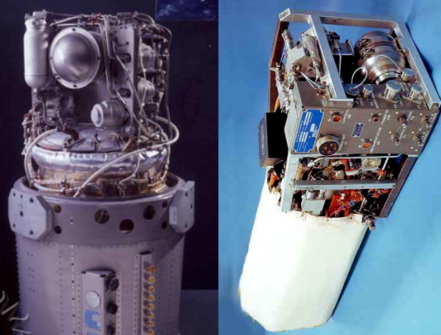
Cutaway diagram of the General Electric 601B
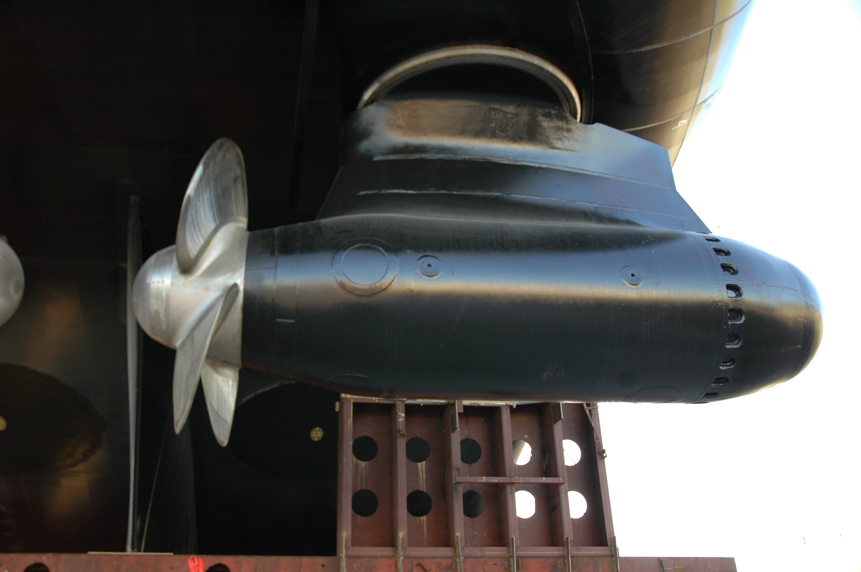
The pod would be slung under a ship or submarine, much like the steerable electric azimuth thrusters popular on modern cruise ships and cargo vessels. Unlike them, this pod would not require any electrical plant onboard ship, freeing up an immense amount of internal volume. It would almost certainly have been fixed in orientation, at least if it had been built in 1961. Now that such thrusters are proven technology though, there’s no reason an atomic version couldn’t be put on a swivel.
A modern electric azimuth thruster.
Two sizes were discussed, a larger pod 60″ in diameter and 360″ long (1.5 m by 9.1 m) that would have weighed 45,000 lbs (20 metric tonnes) and output 15,000 shp (shaft horse power, equivalent to 11 MW). The runtime would have been 5000 hours on 450 lbs (204 kg) of enriched uranium. This is actually comparable to the shaft power of a large modern thruster.
There was also a smaller, 45″ diameter version that would produce only 3750 shp (2796 kW) over the same runtime. In both, the working gas of the turbines would have been neon, probably to minimize the redesign required of the original air-breathing turbine.
Steve seems to think that this podded arrangement would create drag that would prove fatally noisy for a warship, but the Spanish Navy seems to disagree, given that they’re putting azimuth thrusters under their flagship. A submarine might be another issue, but we’ll leave that to the experts. The bigger problem with using these on a warship is the low power for military applications. The contemporary Farragut-class destroyers made 85,000 shp (63 MW) with their steam turbines, so the two-pod ship in the illustration must be both rather small and rather slow.
Concept Art of 601B propulsion pods under a naval vessel, art by General Electric
Of course putting the reactors outside the hull of the ship also makes them very vulnerable to damage. In the 1950s, it might have seemed acceptable that a reactor damaged in battle could simply be dumped onto the seafloor. Nowadays, regulators would likely take a dimmer view of just dropping hundreds of pounds of uranium and tonnes of irradiated metal into the open ocean.
Civilian Applications
Rather than warships, this sort of small, modular reactor sounds perfect for the new fleet of nuclear cargo ships the UN is pushing for to combat climate change. The International Maritime Organization’s goal of net-zero emissions by 2050 is just not going to happen without nuclear power or a complete rethink of our shipping infrastructure. Most of the planning right now seems to center on next-generation small modular reactors: everything from pebble-bed to thorium. This Cold War relic of an idea has a few advantages, though.
Need to refuel? Swap pods. Mechanical problems? Swap pods. The ship and its nuclear power plant are wholly separate, which ought to please regulators and insurers. Converting a ship to use azimuth thrusters is a known factor, and not a huge job in dry dock. There are a great many ships afloat today that will need new engines anyway if they aren’t to be scrapped early and the shipping sector is to meet its ambitious emissions targets. Pulling out their original power plants and popping ‘atomic outboards’ underneath might be the easiest possible solution.
Sure, there are disadvantages to dusting off this hack — and we think a good case can be made that turning a turboprop into a ship-sized outboard ought to qualify as a ‘hack’. For one thing, 5000 hours before refueling isn’t very long. Most commercial cargo ships can cruise at least that long in a single season. But if swapping the pods can be done in-harbor and not in dry dock, that doesn’t seem like an insurmountable obstacle. Besides, there’s no reason to stay 100% faithful to a decades-old design; more fuel capacity is possible.
For another, most of the shielding on these things would have been provided by seawater by design, which is going to make handling the pods out of water an interesting experience. You certainly would not want to see a ship equipped with these pods capsize. Not close up, anyway.
Rather than pass judgement, we ask if General Electric’s “atomic outboard” was just way ahead of its time. What do you think?
Here is a hacker showing off their engineering chops. This video shows successive design iterations for a LEGO vehicle which can cross increasingly large gaps.
At the time of writing this video from [Brick Experiment Channel] has been seen more than 110,000,000 times, which is… rather a lot. We guess with a view count like that there is a fairly good chance that many of our readers have already seen this video, but this is the sort of video one could happily watch twice.
This video sports a bunch of engineering tricks and approaches. We particularly enjoy watching the clever use of center of gravity. They hack gravity to make some of their larger designs work.
To the average person, walking into a flour- or sawmill and seeing dust swirling around is unlikely to evoke much of a response, but those in the know are quite likely to bolt for the nearest exit at this harrowing sight. For as harmless as a fine cloud of flour, sawdust or even coffee creamer may appear, each of these have the potential for a massive conflagration and even an earth-shattering detonation.
As for the ‘why’, the answer can be found in for example the working principle behind an internal combustion engine. While a puddle of gasoline is definitely flammable, the only thing that actually burns is the evaporated gaseous form above the liquid, ergo it’s a relatively slow process; in order to make petrol combust, it needs to be mixed in the right air-fuel ratio. If this mixture is then exposed to a spark, the fuel will nearly instantly burn, causing a detonation due to the sudden release of energy.
Similarly, flour, sawdust, and many other substances in powder form will burn gradually if a certain transition interface is maintained. A bucket of sawdust burns slowly, but if you create a sawdust cloud, it might just blow up the room.
This raises the questions of how to recognize this danger and what to do about it.
Welcome To The Chemical Safety Board
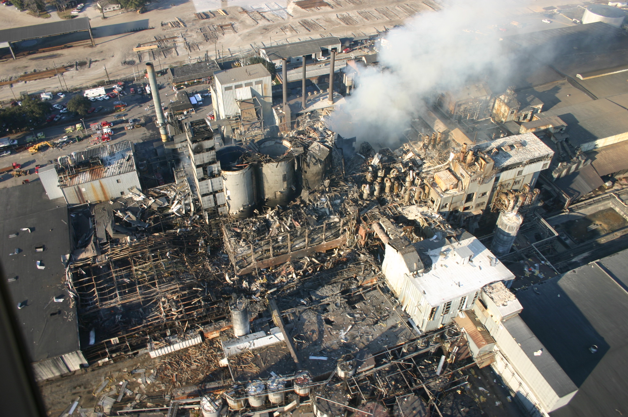
In an industrial setting, people will generally acknowledge that oil refineries and chemical plants are dangerous and can occasionally go boom in rather violent ways. More surprising is that something as seemingly innocuous as a sugar refinery and packing plant can go from a light sprinkling of sugar dust to a violent and lethal explosion within a second. This is however what happened in 2008 at the Georgia Imperial Sugar refinery, which killed fourteen and injured thirty-six. During this disaster, a primary and multiple secondary explosions ripped through the building, completely destroying it.
Georgia Imperial Sugar Refinery aftermath in 2008. (Credit: USCSB)
As described in the US Chemical Safety Board (USCSB) report with accompanying summary video (embedded below), the biggest cause was a lack of ventilation and cleaning that allowed for a build-up of sugar dust, with an ignition source, likely an overheated bearing, setting off the primary explosion. This explosion then found subsequent fuel to ignite elsewhere in the building, setting off a chain reaction.
What is striking is just how simple and straightforward both the build-up towards the disaster and the means to prevent it were. Even without knowing the exact air-fuel ratio for the fuel in question, there are only two points on the scale where you have a mixture that will not violently explode in the presence of an ignition source.
These are either a heavily saturated solution — too much fuel, not enough air — or the inverse. Essentially, if the dust-collection systems at the Imperial Sugar plant had been up to the task, and expanded to all relevant areas, the possibility of an ignition event would have likely been reduced to zero.
Things Like To Burn
In the context of dust explosions, it’s somewhat discomforting to realize just how many things around us are rather excellent sources of fuel. The aforementioned sugar, for example, is a carbohydrate (Cm(H2O)n). This chemical group also includes cellulose, which is a major part of wood dust, explaining why reducing dust levels in a woodworking shop is about much more than just keeping one’s lungs happy. Nobody wants their backyard woodworking shop to turn into a mini-Imperial Sugar ground zero, after all.
Carbohydrates aren’t far off from hydrocarbons, which includes our old friend petrol, as well as methane (CH4), butane (C4H10), etc., which are all delightfully combustible. All that the carbohydrates have in addition to carbon and hydrogen atoms are a lot of oxygen atoms, which is an interesting addition in the context of them being potential fuel sources. It incidentally also illustrates how important carbon is for life on this planet since its forms the literal backbone of its molecules.
Although one might conclude from this that only something which is a carbohydrate or hydrocarbon is highly flammable, there’s a whole other world out there of things that can burn. Case in point: metals.
Lit Metals
On December 9, 2010, workers were busy at the New Cumberland AL Solutions titanium plant in West Virginia, processing titanium powder. At this facility, scrap titanium and zirconium were milled and blended into a powder that got pressed into discs. Per the report, a malfunction inside one blender created a heat source that ignited the metal powder, killing three employees and injuring one contractor. As it turns out, no dust control methods were installed at the plant, allowing for uncontrolled dust build-up.
As pointed out in the USCSB report, both titanium and zirconium will readily ignite in particulate form, with zirconium capable of auto-igniting in air at room temperature. This is why the milling step at AL Solutions took place submerged in water. After ignition, titanium and zirconium require a Class D fire extinguisher, but it’s generally recommended to let large metal fires burn out by themselves. Using water on larger titanium fires can produce hydrogen, leading conceivably to even worse explosions.
The phenomenon of metal fires is probably best known from thermite. This is a mixture of a metal powder and a metal oxide. After ignited by an initial source of heat, the redox process becomes self-sustaining, providing the fuel, oxygen, and heat. While generally iron(III) oxide and aluminium are used, many more metals and metal oxides can be combined, including a copper oxide for a very rapid burn.
While thermite is intentionally kept as a powder, and often in some kind of container to create a molten phase that sustains itself, it shouldn’t be hard to imagine what happens if the metal is ground into a fine powder, distributed as a fine dust cloud in a confined room and exposed to an ignition source. At that point the differences between carbohydrates, hydrocarbons and metals become mostly academic to any survivors of the resulting inferno.
Preventing Dust Explosions
As should be quite obvious at this point, there’s no real way to fight a dust explosion, only to prevent it. Proper ventilation, preventing dust from building up and having active dust extraction in place where possible are about the most minimal precautions one should take. Complacency as happened at the Imperial Sugar plant merely invites disaster: if you can see the dust build-up on surfaces & dust in the air, you’re already at least at DEFCON 2.
A demonstration of how easy it is to create a solid dust explosion came from the Mythbusters back in 2008 when they tested the ‘sawdust cannon’ myth. This involved blowing sawdust into a cloud and igniting it with a flare, creating a massive fireball. After nearly getting their facial hair singed off with this roaring success, they then tried the same with non-dairy coffee creamer, which created an even more massive fireball.
Fortunately the Mythbusters build team was supervised by adults on the bomb range for these experiments, as it shows just how incredibly dangerous dust explosions can be. Even out in the open on a secure bomb range, never mind in an enclosed space, as hundreds have found out over the decades in the US alone. One only has to look at the USCSB’s dust explosions statistics to learn to respect the dangers a bit more.
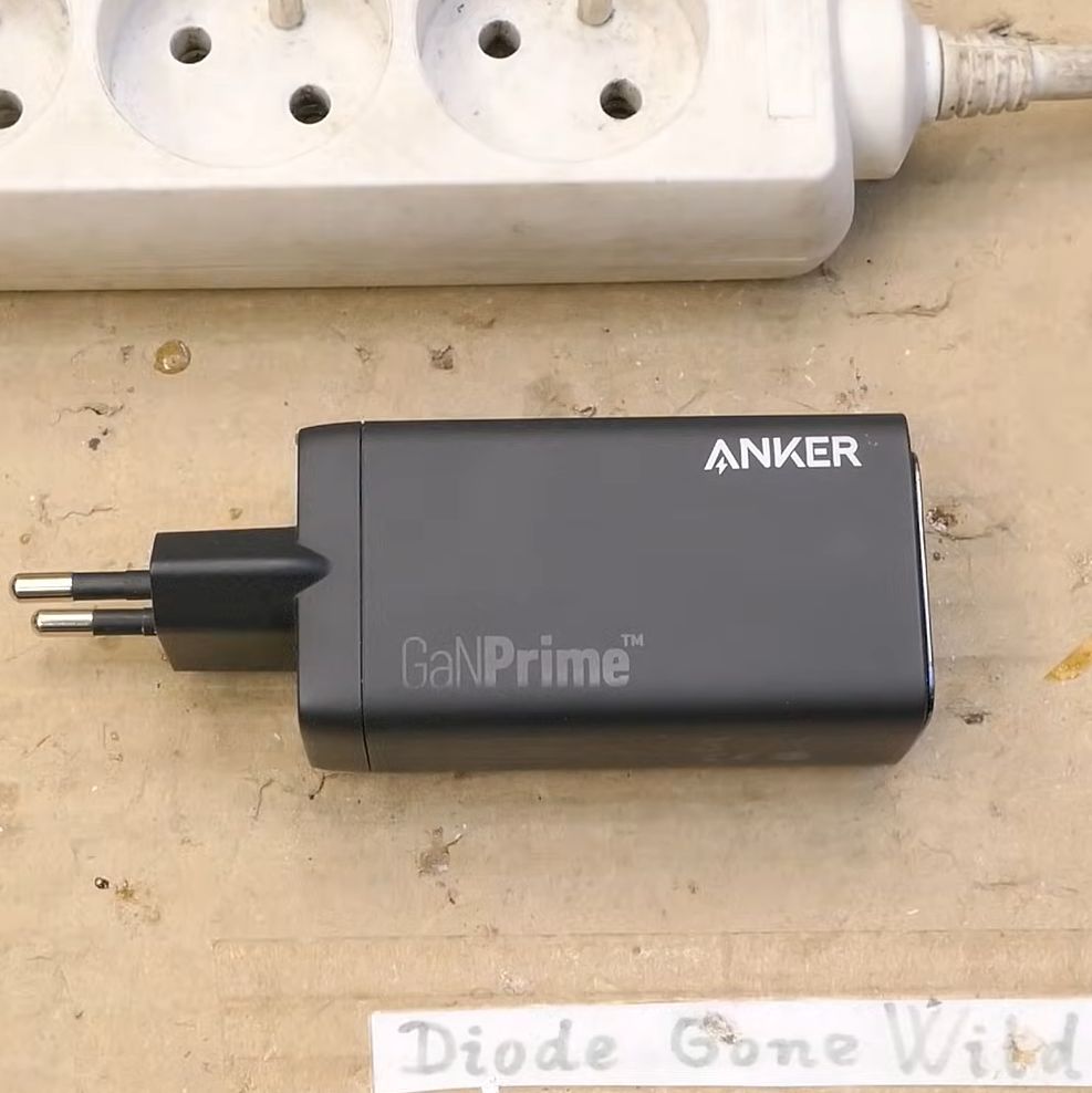
Recently [Florin] was in the market for a basic uninterruptible power supply (UPS) to provide some peace of mind for the smart home equipment he had stashed around. Unfortunately, the cheap Serioux LD600LI unit he picked up left a bit to be desired, and required a bit of retrofitting.
To be fair, the issues that [Florin] ended up dealing with were less about the UPS’ capability to deal with these power issues, and more with the USB interface on the UPS. Initially the UPS seemed to communicate happily with HomeAssistant (HA) via Network UPS Tools over a generic USB protocol, after figuring out what device profile matched this re-branded generic UPS. That’s when HA began to constantly lose the connection with the UPS, risking its integration in the smart home setup.
The old and new USB-serial boards side by side. (Credit: VoltLog, YouTube)
After tearing down the UPS to see what was going on, [Florin] found that it used a fairly generic USB-serial adapter featuring the common Cypress CY7C63310 family of low-speed USB controller. Apparently the firmware on this controller was simply not up to the task or poorly implemented, so a replacement was needed.
The process and implementation is covered in detail in the video. It’s quite straightforward, taking the 9600 baud serial link from the UPS’ main board and using a Silabs CP2102N USB-to-UART controller to create a virtual serial port on the USB side. These conversion boards have to be fully isolated, of course, which is where the HopeRF CMT8120 dual-channel digital isolator comes into play.
After assembly it almost fully worked, except that a Sonoff Zigbee controller in the smart home setup used the same Silabs controller, with thus the same USB PID/VID combo. Fortunately in Silabs AN721 it’s described how you can use an alternate PID (0xEA63) which fixed this issue until the next device with a CP2102N is installed
As it turns out, the cost of a $40 UPS is actually 10 hours of work and $61 in parts, although one cannot put a value on all the lessons learned here.
Near my childhood home was a small river. It wasn’t much more than a creek at the best of times, and in dry summers it would sometimes almost dry up completely. But snowmelt revived it each Spring, and the remains of tropical storms in late Summer and early Fall often transformed it into a raging torrent if only briefly before the flood waters receded and the river returned to its lazy ways.
Other than to those of us who used it as a playground, the river seemed of little consequence. But it did matter enough that a mile or so downstream was some sort of instrumentation, obviously meant to monitor the river. It was — and still is — visible from the road, a tall corrugated pipe standing next to the river, topped with a box bearing the logo of the US Geological Survey. On occasion, someone would visit and open the box to do mysterious things, which suggested the river was interesting beyond our fishing and adventuring needs.
Although I learned quite early that this device was a streamgage, and that it was part of a large network of monitoring instruments the USGS used to monitor the nation’s waterways, it wasn’t until quite recently — OK, this week — that I learned how streamgages work, or how extensive the network is. A lot of effort goes into installing and maintaining this far-flung network, and it’s worth looking at how these instruments work and their impact on everyday life.
Inventing Hydrography
First, to address the elephant in the room, “gage” is a rarely used but accepted alternative spelling of “gauge.” In general, gage tends to be used in technical contexts, which certainly seems to be the case here, as opposed to a non-technical context such as “A gauge of public opinion.” Moreover, the USGS itself uses that spelling, for interesting historical reasons that they’ve apparently had to address often enough that they wrote an FAQ on the subject. So I’ll stick with the USGS terminology in this article, even if I really don’t like it that much.
With that out of the way, the USGS has a long history of monitoring the nation’s rivers. The first streamgaging station was established in 1889 along the Rio Grande River at a railroad station in Embudo, New Mexico. Measurements were entirely manual in those days, performed by crews trained on-site in the nascent field of hydrography. Many of the tools and methods that would be used through the rest of the 19th century to measure the flow of rivers throughout the West and later the rest of the nation were invented at Embudo.
Then as now, river monitoring boils down to one critical measurement: discharge rate, or the volume of water passing a certain point in a fixed amount of time. In the US, discharge rate is measured in cubic feet per second, or cfs. The range over which discharge rate is measured can be huge, from streams that trickle a few dozen cubic feet of water every second to the over one million cfs discharge routinely measured at the mouth of the mighty Mississippi each Spring.
Measurements over such a wide dynamic range would seem to be an engineering challenge, but hydrographers have simplified the problem by cheating a little. While volumetric flow in a closed container like a pipe is relatively easy — flowmeters using paddlewheels or turbines are commonly used for such a task — direct measurement of flow rates in natural watercourses is much harder, especially in navigable rivers where such measuring instruments would pose a hazard to navigation. Instead, the USGS calculates the discharge rate indirectly using stream height, often referred to as flood stage.
Beside Still Waters
Schematic of a USGS stilling well. The water level in the well tracks the height of the stream, with a bit of lag. The height of the water column in the well is easier to read than the surface of the river. Source: USGS, public domain.
The height of a river at any given point is much easier to measure, with the bonus that the tools used for this task lend themselves to continuous measurements. Stream height is the primary data point of each streamgage in the USGS network, which uses several different techniques based on the specific requirements of each site.
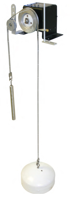
A float-tape gage, with a counterweighted float attached to an encoder by a stainless steel tape. The encoder sends the height of the water column in the stilling well to the data logger. Source: USGS, public domain.
The most common is based on a stilling well. Stilling wells are vertical shafts dug into the bank adjacent to a river. The well is generally large enough for a technician to enter, and is typically lined with either concrete or steel conduit, such as the streamgage described earlier. The bottom of the shaft, which is also lined with an impervious material such as concrete, lies below the bottom of the river bed, while the height of the well is determined by the highest expected flood stage for the river. The lumen of the well is connected to the river via a pair of pipes, which terminate in the water above the surface of the riverbed. Water fills the well via these input pipes, with the level inside the well matching the level of the water in the river.
As the name implies, the stilling well performs the important job of damping any turbulence in the river, allowing for a stable column of water whose height can be easily measured. Most stilling wells measure the height of the water column with a float connected to a shaft encoder by a counterweighted stainless steel tape. Other stilling wells are measured using ultrasonic transducers, radar, or even lidar scanners located in the instrument shelter on the top of the well, which translate time-of-flight to the height of the water column.
While stilling well gages are cheap and effective, they are not without their problems. Chief among these is dealing with silt and debris. Even though intakes are placed above the bottom of the river, silt enters the stilling well and settles into the sump. This necessitates frequent maintenance, usually by flushing the sump and the intake lines using water from a flushing tank located within the stilling well. In rivers with a particularly high silt load, there may be a silt trap between the intakes and the stilling well. Essentially a concrete box with a series of vertical baffles, the silt trap allows silt to settle out of the river water before it enters the stilling well, and must be cleaned out periodically.
Bubbles, Bubbles
Bubble gages often live on pilings or other structures within the watercourse.
Making up for some of the deficiencies of the stilling well is the bubble gage, which measures river stage using gas pressure. A bubble gage typically consists of a small air pump or gas cylinders inside the instrument shelter, plumbed to a pipe that comes out below the surface of the river. As with stilling wells, the tube is fixed at a known point relative to a datum, which is the reference height for that station. The end of the pipe in the water has an orifice of known size, while the supply side has regulators and valves to control the flow of gas. River stage can be measured by sensing the gas pressure in the system, which will increase as the water column above the orifice gets higher.
Bubble gages have a distinct advantage over stilling wells in rivers with a high silt load, since the positive pressure through the orifice tends to keep silt out of the works. However, bubble gages tend to need a steady supply of electricity to power their air pump continuously, or for gages using bottled gas, frequent site visits for replenishment. Also, the pipe run to the orifice needs to be kept fairly short, meaning that bubble gage instrument shelters are often located on pilings within the river course or on bridge abutments, which can make maintenance tricky and pose a hazard to navigation.
While bubble gages and stilling wells are the two main types of gaging stations for fixed installations, the USGS also maintains a selection of temporary gaging instruments for tactical use, often for response to natural disasters. These Rapid Deployment Gages (RDGs) are compact units designed to affix to the rail of a bridge or some other structure across the river. Most RDGs use radar to sense the water level, but some use sonar.
Go With the Flow
No matter what method is used to determine the stage of a river, calculating the discharge rate is the next step. To do that, hydrographers have to head to the field and make flow measurements. By measuring the flow rates at intervals across the river, preferably as close as possible to the gaging station, the total flow through the channel at that point can be estimated, and a calibration curve relating flow rate to stage can be developed. The discharge rate can then be estimated from just the stage reading.
Flow readings are taken using a variety of tools, depending on the size of the river and the speed of the current. Current meters with bucket wheels can be lowered into a river on a pole; the flow rotates the bucket wheel and closes electrical contacts that can be counted on an electromagnetic totalizer. More recently, Acoustic Doppler Current Profilers (ADCPs) have come into use. These use ultrasound to measure the velocity of particulates in the water by their Doppler shift.
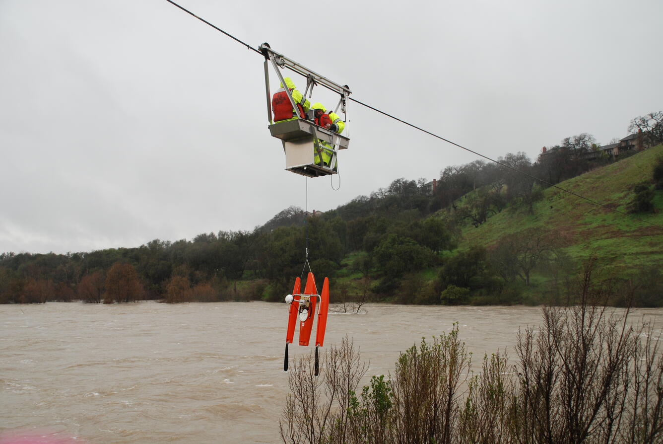
Crews can survey the entire width of a small stream by wading, from boats, or by making measurements from a convenient bridge. In some remote locations where the river is especially swift, the USGS may erect a cableway across the river, so that measurements can be taken at intervals from a cable car.
Nice work if you can get it. USGS crew making flow measurements from a cableway over the American River in California using an Acoustic Doppler Current Profiler. Source: USGS, public domain.
From Paper to Satellites
In the earliest days of streamgaging, recording data was strictly a pen-on-paper process. Station log books were updated by hydrographers for every observation, with results transmitted by mail or telegraph. Later, stations were equipped with paper chart recorders using a long-duration clockwork mechanism. The pen on the chart recorder was mechanically linked to the float in a stilling well, deflecting it as the river stage changed and leaving a record on the chart. Electrical chart recorders came next, with the position of the pen changing based on the voltage through a potentiometer linked to the float.
Chart recorders, while reliable, have the twin disadvantages of needing a site visit to retrieve the data and requiring a tedious manual transcription of the chart data to tabular form. To solve the latter problem, analog-digital recorders (ADRs) were introduced in the 1960s. These recorded stage data on paper tape as four binary-coded decimal (BCD) digits. The time of each stage reading was inferred from its position on the tape, given a known starting time and reading interval. Tapes still had to be retrieved from each station, but at least reading the data back at the office could be automated with a paper tape reader.
In the 1980s and 1990s, gaging stations were upgraded to electronic data loggers, with small solar panels and batteries where grid power wasn’t available. Data was stored locally in the logger between maintenance visits by a hydrographer, who would download the data. Alternately, gaging stations located close to public rights of way sometimes had leased telephone lines for transmitting data at intervals via modem. Later, gaging stations started sprouting cross-polarized Yagi antennas, aimed at one of the Geostationary Operational Environmental Satellites (GOES). Initially, gaging stations used one of the GOES low data rate telemetry channels with a 100 to 300 bps connection. This gave hydrologists near-real-time access to gaging data for the first time. Since 2013, all stations have been upgraded to a high data rate channel that allows up to 1,200 bps telemetry.
Currently, gage data is collected every 15 minutes normally, although the interval can be increased to every 5 minutes at times of peak flow. Data is buffered locally before a GOES uplink, which is about every hour or so, or as often as every 15 minutes in peak flow or emergencies. The uplink frequencies and intervals are very well documented on the USGS site, so you can easily pick them up with an SDR, and you can see if the creek is rising from the comfort of your own shack.
While LEGO themed video games have become something of a staple, in 1997 they were something of an odity. LEGO Island became the first LEGO video game released outside of Japan in 1997 and become something of a hit with over one million copies sold. The game was beloved among fans and set the stage for more LEGO video games to come. In an effort of love, [MattKC] put together a team to reverse engineer the game.
The team set out with the intent to create a near perfect recreation of the codebase, relying on custom made tools to run byte checks on the rewrite compilation and the original binary. While the project is functionally complete, [MattKC] believes it is impossible to get a byte accurate codebase. This is because of what the team called “compiler entropy.” Strange behaviors exists inside of Microsoft’s Visual C++ compiler of the era, and small changes in the code have seemingly random effects to unrelated parts of the binary. To mitigate this issue would likely require either partially reverse engineering Visual C++ or brute forcing the code, both of which would take a large amount of effort and time for no real benefit.
Another interesting step the team had to work out was how the game handled graphics. In the version of Direct X used, the developers could chose between immediate mode and retained mode. The difference largely boils down to how models and assets are handled. In immediate mode, Direct X is largely just a render engine and everything else is handled by the developer. With retained mode, Direct X works more similarly to a game engine where all the model and asset management is handled by Direct X. Almost all developers ended up using immediate mode to the point that Microsoft deprecated support for retained mode. For this reason, if you were to download and run LEGO island on a modern Windows PC, it would yell at you for not having the proper libraries. There is debate about how best to handle this moving forward. The team could rely on an unsupported library from Microsoft, reverse engineer that library only making the functions needed, or using leaked source code.
With the completion of the reverse engineering, engineering can commence. For example, an annoying and persistent bug caused the game to crash if you tried to exit. While it was effective in closing the game, it also caused progress to be lost. That particular bug was fixed simply by initializing a variable in the game’s fronted. Interestingly, that bug was not present in the late betas of the game that had been dug up from the depths of the internet leading to questions as to why a rewrite of the fronted was necessary so late in the development. Now efforts are commencing to port the game to other platforms which bring with it fresh headaches including rewriting for OpenGL and the balance of keeping a historically accurate game with the needs of modern development.
Typically, when we think about forming metal parts, we think about beating them with hammers, or squeezing them with big hydraulic presses. But what if magnets could do the squeezing? As it turns out—Grumman Aerospace discovered they can, several decades ago! Even better, they summed up this technique in a great educational video which we’ve placed below the break.
The video concerns the development of the Grumman EMF Torque Tube. The parts are essentially tubes with gear-like fittings mounted in either end, which are fixed with electromagnetic forming techniques instead of riveting or crimping. Right away, we’re told the key benefits—torque tubes built this way are “stronger, lighter, and more fatigue resistant” than those built with conventional techniques. Grumman used these torque tubes in such famous aircraft as the F-14 Tomcat, highlighting their performance and reliability.
Before……and after. The part is formed and the coil is destroyed.
The video goes on to explain the basics of the EMF torque tube production process. A tube is placed inside a coil, with the end fitting then installed inside. A capacitor bank dumps current through the coil to generate a strong electromagnetic field. This field is opposed by a secondary field generated by eddy currents. The two forces result in an explosive force which drives the tube inwards, gripping into the grooves of the end fitting, and destroys the coil in the process. Grumman notes that it specifically optimized a grooving profile for bonding tubes with end fittings, which maximised the strength of these EMF-produced joints.
This tip was sent in by [irox]. The video itself was posted by [Greg Benoit], who notes his father Robert Benoit was intimately involved with the development of the technique. Indeed, it was useful enough that the technology was licensed to Boeing, generating many millions of dollars for Grumman.
We feature all kinds of machining and forming techniques here, but this sort of forming isn’t something we see a lot of around these parts. Still, we’re sure someone will be Kickstarting a home EMF forming machine before the end of next week.
If we asked you to think of a device that converts a chemical reaction into electricity, you’d probably say we were thinking of a battery. That’s true, but there is another device that does this that is both very similar and very different from a battery: the fuel cell.
In a very simple way, you can think of a fuel cell as a battery that consumes the chemicals it uses and allows you to replace those chemicals so that, as long as you have fuel, you can have electricity. However, the truth is a little more complicated than that. Batteries are energy storage devices. They run out when the energy stored in the chemicals runs out. In fact, many batteries can take electricity and reverse the chemical reaction, in effect recharging them. Fuel cells react chemicals to produce electricity. No fuel, no electricity.
Superficially, the two devices seem very similar. Like batteries, fuel cells have an anode and a cathode. They also have an electrolyte, but its purpose isn’t the same as in a conventional battery. Typically, a catalyst causes fuel to oxidize, creating positively charged ions and electrons. These ions move from the anode to the cathode, and the electrons move from the anode, through an external circuit, and then to the cathode, so electric current occurs. As a byproduct, many fuel cells produce potentially useful byproducts like water. NASA has the animation below that shows how one type of cell works.
History
Sir William Grove seems to have made the first fuel cell in 1838, publishing in The London and Edinburgh Philosophical Magazine and Journal of Science. His fuel cell used dilute acid, copper sulphate, along with sheet metal and porcelain. Today, the phosphoric acid fuel cell is similar to Grove’s design.
The Bacon fuel cell is due to Francis Thomas Bacon and uses alkaline fuel. Modern versions of this are in use today by NASA and others. Although Bacon’s fuel cell could produce 5 kW, it was General Electric in 1955 that started creating larger units. GE chemists developed an ion exchange membrane that included a platinum catalyst. Named after the developers, the “Grubb-Niedrach” fuel cell flew in Gemini space capsules. By 1959, a fuel cell tractor prototype was running, as well as a welding machine powered by a Bacon cell.
One of the reasons spacecraft often use fuel cells is that many cells take hydrogen and oxygen as fuel and put out electricity and water. There are already gas tanks available, and you can always use water.
Types of Fuel Cells
Not all fuel cells use the same fuel or produce the same byproducts. At the anode, a catalyst ionizes the fuel, which produces a positive ion and a free electron. The electrolyte, often a membrane, can pass ions, but not the electrons. That way, the ions move towards the cathode, but the electrons have to find another way — through the load — to get to the cathode. When they meet again, a reaction with more fuel and a catalyst produces the byproduct: hydrogen and oxygen form water.
Most common cells use hydrogen and oxygen with an anode catalyst of platinum and a cathode catalyst of nickel. The voltage output per cell is often less than a volt. However, some fuel cells use hydrocarbons. Diesel, methanol, and other hydrocarbons can produce electricity and carbon dioxide as a byproduct, along with water. You can even use some unusual organic inputs, although to be fair, those are microbial fuel cells.
Common types include:
Alkaline – The Bacon cell was a fixture in space capsules, using carbon electrodes, a catalyst, and a hydroxide electrolyte.
Solid acid – These use a solid acid material as electrolyte. The material is heated to increase conductivity.
Phosphoric acid – Another acid-based technology that operates at hotter temperatures.
Molten carbonate – These work at high temperatures using lithium potassium carbonate as an electrolyte.
Solid oxide – Another high temperature that uses zirconia ceramic as the electrolyte.
In addition to technology, you can consider some fuel cells as stationary — typically producing a lot of power for consumption by some power grid — or mobile.
Using fuel cells in stationary applications is attractive partly because they have no moving parts. However, you need a way to fuel it and — if you want efficiency — you need a way to harness the waste heat produced. It is possible, for example, to use solar power to turn water into gas and then use that gas to feed a fuel cell. It is possible to use the heat directly or to convert it to electricity in a more conventional way.
Space
Fuel cells have a long history in space. You can see how alkaline Bacon cells were used in early fuel cells in the video below.
Very early fuel cells — starting with Gemini in 1962 — used a proton exchange membrane. However, in 1967, NASA started using Nafion from DuPont, which was improved over the old membranes.
However, alkaline cells had vastly improved power density, and from Apollo on, these cells, using a potassium hydroxide electrolyte, were standard issue.
Even the Shuttle had fuel cells. Russian spacecraft also had fuel cells, starting with a liquid oxygen-hydrogen cell used on the Soviet Lunar Orbital Spacecraft (LOK).
The shuttle’s power plant measured 14 x 15 x 45 inches and weighed 260 pounds. They were installed under the payload bay, just aft of the crew compartment. They drew cryogenic gases from nearby tanks and could provide 12 kW continuously, and up to 16 kW. However, they typically were taxed at about 50% capacity. Each orbiter’s power plant contained 96 individual cells connected to achieve a 28-volt output.
Going Mobile
There have been attempts to make fuel cell cars, but with the difficulty of delivering, storing, and transporting hydrogen, there has been resistance. The Toyota Mirai, for example, costs $57,000, yet owners sued because they couldn’t obtain hydrogen. Some buses use fuel cells, and a small number of trains (including the one mentioned in the video below).
Surprisingly, there is a market for forklifts using fuel cells. The clean output makes them ideal for indoor operation. Batteries? They take longer to charge and don’t work well in the cold. Fuel cells don’t mind the cold, and you can top them off in three minutes.
There have been attempts to put fuel cells into any vehicle you can imagine. Airplanes, motorcycles, and boats sporting fuel cells have all made the rounds.
Can You DIY?
We have seen a few fuel cell projects, but they all seem to vanish over time. In theory, it shouldn’t be that hard, unless you demand commercial efficiency. However, it can be done, as you can see in the video below. If you make a fuel cell, be sure to send us a tip so we can spread the word.
Taking a break from his usual prodding at suspicious AliExpress USB chargers, [DiodeGoneWild] recently had a gander at what used to be a good USB charger.
The Anker 737 USB charger prior to its autopsy.
Before it went completely dead, the Anker 737 GaNPrime USB charger which a viewer sent him was capable of up to 120 Watts combined across its two USB-C and one USB-A outputs. Naturally the charger’s enclosure couldn’t be opened non-destructively, and it turned out to have (soft) potting compound filling up the voids, making it a treat to diagnose. Suffice it to say that these devices are not designed to be repaired.
With it being an autopsy, the unit got broken down into the individual PCBs, with a short detected that eventually got traced down to an IC marked ‘SW3536’, which is one of the ICs that communicates with the connected USB device to negotiate the voltage. With the one IC having shorted, it appears that it rendered the entire charger into an expensive paperweight.
Since the charger was already in pieces, the rest of the circuit and its ICs were also analyzed. Here the gallium nitride (GaN) part was found in the Navitas GaNFast NV6136A FET with integrated gate driver, along with an Infineon CoolGaN IGI60F1414A1L integrated power stage. Unfortunately all of the cool technology was rendered useless by one component developing a short, even if it made for a fascinating look inside one of these very chonky USB chargers.
Saw what you want about the wisdom of keeping a 50-year-old space mission going, but the dozen or so people still tasked with keeping the Voyager mission running are some major studs. That’s our conclusion anyway, after reading about the latest heroics that revived a set of thrusters on Voyager 1 that had been offline for over twenty years. The engineering aspects of this feat are interesting enough, but we’re more interested in the social engineering aspects of this exploit, which The Register goes into a bit. First of all, even though both Voyagers are long past their best-by dates, they are our only interstellar assets, and likely will be for centuries to come, or perhaps forever. Sure, the rigors of space travel and the ravages of time have slowly chipped away at what these machines can so, but while they’re still operating, they’re irreplaceable assets.
That makes the fix to the thruster problem all the more ballsy, since the Voyager team couldn’t be 100% sure about the status of the primary thrusters, which were shut down back in 2004. They thought it might have been that the fuel line heaters were still good, but if they actually had gone bad, trying to switch the primary thrusters back on with frozen fuel lines could have resulted in an explosion when Voyager tried to fire them, likely ending in a loss of the spacecraft. So the decision to try this had to be a difficult one, to say the least. Add in an impending shutdown of the only DSN antenna capable of communicating with the spacecraft and a two-day communications round trip, and the pressure must have been unbearable. But they did it, and Voyager successfully navigated yet another crisis. But what we’re especially excited about is discovering a 2023 documentary about the current Voyager mission team called “It’s Quieter in the Twilight.” We know what we’ll be watching this weekend.
Speaking of space exploration, one thing you don’t want to do is send anything off into space bearing Earth microbes. That would be a Very Bad Thing, especially for missions designed to look for life anywhere else but here. But, it turns out that just building spacecraft in cleanrooms might not be enough, with the discovery of 26 novel species of bacteria growing in the cleanroom used to assemble a Mars lander. The mission in question was Phoenix, which landed on Mars in 2008 to learn more about the planet’s water. In 2007, while the lander was in the Payload Hazardous Servicing Facility at Kennedy Space Center, biosurveillance teams collected samples from the cleanroom floor. Apparently, it wasn’t very clean, with 215 bacterial strains isolated, 26 of which were novel. What’s more, genomic analysis of the new bugs suggests they have genes that make them especially tough, both in their resistance to decontamination efforts on Earth and in their ability to survive the rigors of life in space. We’re not really sure if these results say more about NASA’s cleanliness than they do about the selective pressure that an extreme environment like a cleanroom exerts on fast-growing organisms like bacteria. Either way, it doesn’t bode well for our planetary protection measures.
Closer to home but more terrifying is video from an earthquake in Myanmar that has to be seen to be believed. And even then, what’s happening in the video is hard to wrap your head around. It’s not your typical stuff-falling-off-the-shelf video; rather, the footage is from an outdoor security camera that shows the ground outside of a gate literally ripping apart during the 7.7 magnitude quake in March. The ground just past the fence settles a bit while moving away from the camera a little, but the real action is the linear motion — easily three meters in about two seconds. The motion leaves the gate and landscaping quivering but largely intact; sadly, the same can’t be said for a power pylon in the distance, which crumples as if it were made from toothpicks.
And finally, “Can it run DOOM?” has become a bit of a meme in our community, a benchmark against which hacking chops can be measured. If it has a microprocessor in it, chances are someone has tried to make it run the classic first-person shooter video game. We’ve covered dozens of these hacks before, everything from a diagnostic ultrasound machine to a custom keyboard keycap, while recent examples tend away from hardware ports to software platforms such as a PDF file, Microsoft Word, and even SQL. Honestly, we’ve lost count of the ways to DOOM, which is where Can It Run Doom? comes in handy. It lists all the unique platforms that hackers have tortured into playing the game, as well as links to source code and any relevant video proof of the exploit. Check it out the next time you get the urge to port DOOM to something cool; you wouldn’t want to go through all the work to find out it’s already been done, would you?
Once a printed circuit board (PCB) has been assembled it’s rather hard to look inside of it, which can be problematic when you have e.g. a multilayer PCB of an (old) system that you really would like to dissect to take a look at the copper layers and other details that may be hidden inside, such as Easter eggs on inner layers. [Lorentio Brodeso]’s ‘LACED’ project offers one such method, using both chemical etching and a 5 Watt diode engraving laser to remove the soldermask, copper and FR4 fiberglass layers.
This project uses sodium hydroxide (NaOH) to dissolve the solder mask, followed by hydrogen chloride (HCl) and hydrogen peroxide (H2O2) to dissolve the copper in each layer. The engraving laser is used for the removing of the FR4 material. Despite the ‘LACED’ acronym standing for Laser-Controlled Etching and Delayering, the chemical method(s) and laser steps are performed independently from each other.
This makes it in a way a variation on the more traditional CNC-based method, as demonstrated by [mikeselectricstuff] (as shown in the top image) back in 2016, alongside the detailed setup video of how a multi-layer PCB was peeled back with enough resolution to make out each successive copper and fiberglass layer.
The term ‘laser-assisted etching’ is generally used for e.g. glass etching with HF or KOH in combination with a femtosecond laser to realize high-resolution optical features, ‘selective laser etching’ where the etchant is assisted by the laser-affected material, or the related laser-induced etching of hard & brittle materials. Beyond these there is a whole world of laser-induced or laser-activated etching or functionalized methods, all of which require that the chemical- and laser-based steps are used in unison.
Aside from this, the use of chemicals to etch away soldermask and copper does of course leave one with a similar messy clean-up as when etching new PCBs, but it can provide more control due to the selective etching, as a CNC’s carbide bit will just as happily chew through FR4 as copper. When reverse-engineering a PCB you will have to pick whatever method works best for you.
Top image: Exposed inner copper on multilayer PCB. (Credit: mikeselectricstuff, YouTube)
If you talk about Starlink, you are usually talking about the satellites that orbit the Earth carrying data to and from ground stations. Why not? Space is cool. But there’s another important part of the system: the terminals themselves. Thanks to [DarkNavy], you don’t have to tear one open yourself to see what’s inside.
The terminal consists of two parts: the router and the antenna. In this context, antenna is somewhat of a misnomer, since it is really the RF transceiver and antenna all together. The post looks only at the “antenna” part of the terminal.
The unit is 100% full of printed circuit board with many RF chips and a custom ST Microelectronics Cortex A-53 quad-core CPU. There was a hack to gain root shell on the device. This led to SpaceX disabling the UART via a firmware update. However, there is still a way to break in.
[DarkNavy] wanted to look at the code, too, but there was no easy way to dump the flash memory. Desoldering the eMMC chip and reading it was, however, productive. The next step was to create a virtual environment to run the software under Qemu.
There were a few security questions raised. We wouldn’t call them red flags, per see, but maybe pink flags. For example, there are 41 trusted ssh keys placed in the device’s authorized_keys file. That seems like a lot for a production device on your network, but it isn’t any smoking gun.
We’ve watched the cat-and-mouse between Starlink and people hacking the receivers with interest.