Vista Normal

Hay nuevos artículos disponibles. Pincha para refrescar la página.
Hoy — 23 Abril 2025Salida Principal

To See Within: Detecting X-Rays

23 Abril 2025 at 14:00

It’s amazing how quickly medical science made radiography one of its main diagnostic tools. Medicine had barely emerged from its Dark Age of bloodletting and the four humours when X-rays were discovered, and the realization that the internal structure of our bodies could cast shadows of this mysterious “X-Light” opened up diagnostic possibilities that went far beyond the educated guesswork and exploratory surgery doctors had relied on for centuries.

The problem is, X-rays are one of those things that you can’t see, feel, or smell, at least mostly; X-rays cause visible artifacts in some people’s eyes, and the pencil-thin beam of a CT scanner can create a distinct smell of ozone when it passes through the nasal cavity — ask me how I know. But to be diagnostically useful, the varying intensities created by X-rays passing through living tissue need to be translated into an image. We’ve already looked at how X-rays are produced, so now it’s time to take a look at how X-rays are detected and turned into medical miracles.

Taking Pictures

For over a century, photographic film was the dominant way to detect medical X-rays. In fact, years before Wilhelm Conrad Röntgen’s first systematic study of X-rays in 1895, fogged photographic plates during experiments with a Crooke’s tube were among the first indications of their existence. But it wasn’t until Röntgen convinced his wife to hold her hand between one of his tubes and a photographic plate to create the first intentional medical X-ray that the full potential of radiography could be realized.

“Hand mit Ringen” by W. Röntgen, December 1895. Public domain.

The chemical mechanism that makes photographic film sensitive to X-rays is essentially the same as the process that makes light photography possible. X-ray film is made by depositing a thin layer of photographic emulsion on a transparent substrate, originally celluloid but later polyester. The emulsion is a mixture of high-grade gelatin, a natural polymer derived from animal connective tissue, and silver halide crystals. Incident X-ray photons ionize the halogens, creating an excess of electrons within the crystals to reduce the silver halide to atomic silver. This creates a latent image on the film that is developed by chemically converting sensitized silver halide crystals to metallic silver grains and removing all the unsensitized crystals.

Other than in the earliest days of medical radiography, direct X-ray imaging onto photographic emulsions was rare. While photographic emulsions can be exposed by X-rays, it takes a lot of energy to get a good image with proper contrast, especially on soft tissues. This became a problem as more was learned about the dangers of exposure to ionizing radiation, leading to the development of screen-film radiography.

In screen-film radiography, X-rays passing through the patient’s tissues are converted to light by one or more intensifying screens. These screens are made from plastic sheets coated with a phosphorescent material that glows when exposed to X-rays. Calcium tungstate was common back in the day, but rare earth phosphors like gadolinium oxysulfate became more popular over time. Intensifying screens were attached to the front and back covers of light-proof cassettes, with double-emulsion film sandwiched between them; when exposed to X-rays, the screens would glow briefly and expose the film.

By turning one incident X-ray photon into thousands or millions of visible light photons, intensifying screens greatly reduce the dose of radiation needed to create diagnostically useful images. That’s not without its costs, though, as the phosphors tend to spread out each X-ray photon across a physically larger area. This results in a loss of resolution in the image, which in most cases is an acceptable trade-off. When more resolution is needed, single-screen cassettes can be used with one-sided emulsion films, at the cost of increasing the X-ray dose.

Wiggle Those Toes

Intensifying screens aren’t the only place where phosphors are used to detect X-rays. Early on in the history of radiography, doctors realized that while static images were useful, continuous images of body structures in action would be a fantastic diagnostic tool. Originally, fluoroscopy was performed directly, with the radiologist viewing images created by X-rays passing through the patient onto a phosphor-covered glass screen. This required an X-ray tube engineered to operate with a higher duty cycle than radiographic tubes and had the dual disadvantages of much higher doses for the patient and the need for the doctor to be directly in the line of fire of the X-rays. Cataracts were enough of an occupational hazard for radiologists that safety glasses using leaded glass lenses were a common accessory.

How not to test your portable fluoroscope. The X-ray tube is located in the upper housing, while the image intensifier and camera are below. The machine is generally referred to as a “C-arm” and is used in the surgery suite and for bedside pacemaker placements. Source: Nightryder84, CC BY-SA 3.0.

One ill-advised spin-off of medical fluoroscopy was the shoe-fitting fluoroscopes that started popping up in shoe stores in the 1920s. Customers would stick their feet inside the machine and peer at a fluorescent screen to see how well their new shoes fit. It was probably not terribly dangerous for the once-a-year shoe shopper, but pity the shoe salesman who had to peer directly into a poorly regulated X-ray beam eight hours a day to show every Little Johnny’s mother how well his new Buster Browns fit.

As technology improved, image intensifiers replaced direct screens in fluoroscopy suites. Image intensifiers were vacuum tubes with a large input window coated with a fluorescent material such as zinc-cadmium sulfide or sodium-cesium iodide. The phosphors convert X-rays passing through the patient to visible light photons, which are immediately converted to photoelectrons by a photocathode made of cesium and antimony. The electrons are focused by coils and accelerated across the image intensifier tube by a high-voltage field on a cylindrical anode. The electrons pass through the anode and strike a phosphor-covered output screen, which is much smaller in diameter than the input screen. Incident X-ray photons are greatly amplified by the image intensifier, making a brighter image with a lower dose of radiation.

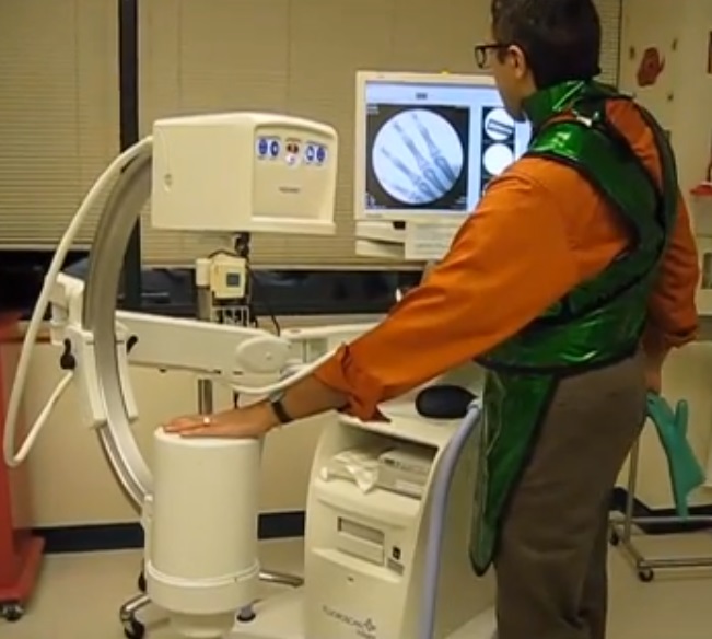
Originally, the radiologist viewed the output screen using a microscope, which at least put a little more hardware between his or her eyeball and the X-ray source. Later, mirrors and lenses were added to project the image onto a screen, moving the doctor’s head out of the direct line of fire. Later still, analog TV cameras were added to the optical path so the images could be displayed on high-resolution CRT monitors in the fluoroscopy suite. Eventually, digital cameras and advanced digital signal processing were introduced, greatly streamlining the workflow for the radiologist and technologists alike.

Get To The Point

So far, all the detection methods we’ve discussed fall under the general category of planar detectors, in that they capture an entire 2D shadow of the X-ray beam after having passed through the patient. While that’s certainly useful, there are cases where the dose from a single, well-defined volume of tissue is needed. This is where point detectors come into play.

Nuclear medicine image, or scintigraph, of metastatic cancer. 99Tc accumulates in lesions in the ribs and elbows (A), which are mostly resolved after chemotherapy (B). Note the normal accumulation of isotope in the kidneys and bladder. Kazunari Mado, Yukimoto Ishii, Takero Mazaki, Masaya Ushio, Hideki Masuda and Tadatoshi Takayama, CC BY-SA 2.0.

In medical X-ray equipment, point detectors often rely on some of the same gas-discharge technology that DIYers use to build radiation detectors at home. Geiger tubes and ionization chambers measure the current created when X-rays ionize a low-pressure gas inside an electric field. Geiger tubes generally use a much higher voltage than ionization chambers, and tend to be used more for radiological safety, especially in nuclear medicine applications, where radioisotopes are used to diagnose and treat diseases. Ionization chambers, on the other hand, were often used as a sort of autoexposure control for conventional radiography. Tubes were placed behind the film cassette holders in the exam tables of X-ray suites and wired into the control panels of the X-ray generators. When enough radiation had passed through the patient, the film, and the cassette into the ion chamber to yield a correct exposure, the generator would shut off the X-ray beam.

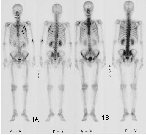
Another kind of point detector for X-rays and other kinds of radiation is the scintillation counter. These use a crystal, often cesium iodide or sodium iodide doped with thallium, that releases a few visible light photons when it absorbs ionizing radiation. The faint pulse of light is greatly amplified by one or more photomultiplier tubes, creating a pulse of current proportional to the amount of radiation. Nuclear medicine studies use a device called a gamma camera, which has a hexagonal array of PM tubes positioned behind a single large crystal. A patient is injected with a radioisotope such as the gamma-emitting technetium-99, which accumulates mainly in the bones. Gamma rays emitted are collected by the gamma camera, which derives positional information from the differing times of arrival and relative intensity of the light pulse at the PM tubes, slowly building a ghostly skeletal map of the patient by measuring where the 99Tc accumulated.

Going Digital

Despite dominating the industry for so long, the days of traditional film-based radiography were clearly numbered once solid-state image sensors began appearing in the 1980s. While it was reliable and gave excellent results, film development required a lot of infrastructure and expense, and resulted in bulky films that required a lot of space to store. The savings from doing away with all the trappings of film-based radiography, including the darkrooms, automatic film processors, chemicals, silver recycling, and often hundreds of expensive film cassettes, is largely what drove the move to digital radiography.

After briefly flirting with phosphor plate radiography, where a sensitized phosphor-coated plate was exposed to X-rays and then “developed” by a special scanner before being recharged for the next use, radiology departments embraced solid-state sensors and fully digital image capture and storage. Solid-state sensors come in two flavors: indirect and direct. Indirect sensor systems use a large matrix of photodiodes on amorphous silicon to measure the light given off by a scintillation layer directly above it. It’s basically the same thing as a film cassette with intensifying screens, but without the film.

Direct sensors, on the other hand, don’t rely on converting the X-ray into light. Rather, a large flat selenium photoconductor is used; X-rays absorbed by the selenium cause electron-hole pairs to form, which migrate to a matrix of fine electrodes on the underside of the sensor. The current across each pixel is proportional to the amount measured to the amount of radiation received, and can be read pixel-by-pixel to build up a digital image.

A Scratch-Built Commodore 64, Turing Style

23 Abril 2025 at 08:00

Building a Commodore 64 is among the easier projects for retrocomputing fans to tackle. That’s because the C64’s core chipset does most of the heavy lifting; source those and you’re probably 80% of the way there. But what if you can’t find those chips, or if you want more of a challenge than plugging and chugging? Are you out of luck?

Hardly. The video below from [DrMattRegan] is the first in a series on his scratch-built C64 that doesn’t use the core chipset, and it looks pretty promising. This video concentrates on building a replacement for the 6502 microprocessor — actually the 6510, but close enough — using just a couple of EPROMs, some SRAM chips, and a few standard logic chips to glue everything together. He uses the EPROMs as a “rulebook” that contains the code to emulate the 6502 — derived from his earlier Turing 6502 project — and the SRAM chips as a “notebook” for scratch memory and registers to make a Turing-complete random access machine.

[DrMatt] has made good progress so far, with the core 6502 CPU built on a PCB and able to run the Apple II version of Pac-Man as a benchmark. We’re looking forward to the rest of this series, but in the meantime, a look back at his VIC-less VIC-20 project might be informative.

Thanks to [Clint] for the tip.

AnteayerSalida Principal

Hackaday Links: April 20, 2025

20 Abril 2025 at 23:00
Hackaday Links Column Banner

We appear to be edging ever closer to a solid statement of “We are not alone” in the universe with this week’s announcement of the detection of biosignatures in the atmosphere of exoplanet K2-18b. The planet, which is 124 light-years away, has been the focus of much attention since it was discovered in 2015 using the Kepler space telescope because it lies in the habitable zone around its red-dwarf star. Initial observations with Hubble indicated the presence of water vapor, and follow-up investigations using the James Webb Space Telescope detected all sorts of goodies in the atmosphere, including carbon dioxide and methane. But more recently, JWST saw signs of dimethyl sulfide (DMS) and dimethyl disulfide (DMDS), organic molecules which, on Earth, are strongly associated with biological processes in marine bacteria and phytoplankton.

The team analyzing the JWST data says that the data is currently pretty good, with a statistical significance of 99.7%. That’s a three-sigma result, and while it’s promising, it’s not quite good enough to seal the deal that life evolved more than once in the universe. If further JWST observations manage to firm that up to five sigma, it’ll be the most important scientific result of all time. To our way of thinking, it would be much more significant than finding evidence of ancient or even current life in our solar system, since cross-contamination is so easy in the relatively cozy confines of the Sun’s gravity well. K2-18b is far enough away from our system as to make that virtually impossible, and that would say a lot about the universality of biochemical evolution. It could also provide an answer to the Fermi Paradox, since it could indicate that the galaxy is actually teeming with life but under conditions that make it difficult to evolve into species capable of making detectable techno-signatures. It’s hard to build a radio or a rocket when you live on a high-g water world, after all.

Closer to home, there’s speculation that the famous Antikythera mechanism may not have worked at all in its heyday. According to researchers from Universidad Nacional de Mar del Plata in Argentina, “the world’s first analog computer” could not have worked due to the accumulated mechanical error of its gears. They blame this on the shape of the gear teeth, which appear triangular on CT scans of the mechanism, and which they seem to attribute to manufacturing defects. Given the 20-odd centuries the brass-and-iron device spent at the bottom of the Aegean Sea and the potential for artifacts in CT scans, we’re not sure it’s safe to pin the suboptimal shape of the gear teeth on the maker of the mechanism. They also seem to call into question the ability of 1st-century BCE craftsmen to construct a mechanism with sufficient precision to serve as a useful astronomical calculator, a position that Chris from Clickspring has been putting the lie to with his ongoing effort to reproduce the Antikythera mechanism using ancient tools and materials. We’re keen to hear what he has to say about this issue.

Speaking of questionable scientific papers, have you heard about “vegetative electron microscopy”? It’s all the rage, having been mentioned in at least 22 scientific papers recently, even though no such technique exists. Or rather, it didn’t exist until around 2017, when it popped up in a couple of Iranian scientific papers. How it came into being is a bit of a mystery, but it may have started with faulty scans of a paper from the 1950s, which had the terms “vegetative” and “electron microscopy” printed in different columns but directly across from each other. That somehow led to the terms getting glued together, possibly in one of those Iranian papers because the Farsi spelling of “vegetative” is very similar to “scanning,” a much more sensible prefix to “electron microscopy.” Once the nonsense term was created, it propagated into subsequent papers of dubious scientific provenance by authors who didn’t bother to check their references, or perhaps never existed in the first place. The wonders of our AI world never cease to amaze.

And finally, from the heart of Silicon Valley comes a tale of cyber hijinks as several crosswalks were hacked to taunt everyone’s favorite billionaires. Twelve Palo Alto crosswalks were targeted by persons unknown, who somehow managed to gain access to the voice announcement system in the crosswalks and replaced the normally helpful voice messages with deep-fake audio of Elon Musk and Mark Zuckerberg saying ridiculous but plausible things. Redwood City and Menlo Park crosswalks may have also been attacked, and soulless city officials responded by disabling the voice feature. We get why they had to do it, but as cyberattacks go, this one seems pretty harmless.

Designing an FM Drum Synth from Scratch

17 Abril 2025 at 20:00

How it started: a simple repair job on a Roland drum machine. How it ended: a scratch-built FM drum synth module that’s completely analog, and completely cool.

[Moritz Klein]’s journey down the analog drum machine rabbit hole started with a Roland TR-909, a hybrid drum machine from the mid-80s that combined sampled sounds with analog synthesis. The unit [Moritz] picked up was having trouble with the decay on the kick drum, so he spread out the gloriously detailed schematic and got to work. He breadboarded a few sections of the kick drum circuit to aid troubleshooting, but one thing led to another and he was soon in new territory.

The video below is on the longish side, with the first third or so dedicated to recreating the circuits used to create the 909’s iconic sound, slightly modifying some of them to simplify construction. Like the schematic that started the whole thing, this section of the video is jam-packed with goodness, too much to detail here. But a few of the gems that caught our eye were the voltage-controlled amplifier (VCA) circuit that seems to make appearances in multiple places in the circuit, and the dead-simple wave-shaper circuit, which takes some of the harmonics out of the triangle wave oscillator’s output with just a couple of diodes and some resistors.

Once the 909’s kick and toms section had been breadboarded, [Moritz] turned his attention to adding something Roland hadn’t included: frequency modulation. He did this by adding a second, lower-frequency voltage-controlled oscillator (VCO) and using that to modulate the drum section. That resulted in a weird, metallic sound that can be tuned to imitate anything from a steel drum to a bell. He also added a hi-hat and cymbal section by mixing the square wave outputs on the VCOs through a funky XOR gate made from discrete components and a high-pass filter.

There’s a lot of information packed into this video, and by breaking everything down into small, simple blocks, [Moritz] makes it easy to understand analog synths and the circuits behind them.

An Absolute Zero of a Project

17 Abril 2025 at 02:00

How would you go about determining absolute zero? Intuitively, it seems like you’d need some complicated physics setup with lasers and maybe some liquid helium. But as it turns out, all you need is some simple lab glassware and a heat gun. And a laser, of course.

To be clear, the method that [Markus Bindhammer] describes in the video below is only an estimation of absolute zero via Charles’s Law, which describes how gases expand when heated. To gather the needed data, [Marb] used a 50-ml glass syringe mounted horizontally on a stand and fitted with a thermocouple. Across from the plunger of the syringe he placed a VL6180 laser time-of-flight sensor, to measure the displacement of the plunger as the air within it expands.

Data from the TOF sensor and the thermocouple were recorded by a microcontroller as the air inside the syringe was gently heated. Plotting the volume of the gas versus the temperature results shows a nicely linear relationship, and the linear regression can be used to calculate the temperature at which the volume of the gas would be zero. The result: -268.82°C, or only about four degrees off from the accepted value of -273.15°. Not too shabby.

[Marb] has been on a tear lately with science projects like these; check out his open-source blood glucose measurement method or his all-in-one electrochemistry lab.

Homemade VNA Delivers High-Frequency Performance on a Budget

16 Abril 2025 at 11:00

With vector network analyzers, the commercial offerings seem to come in two flavors: relatively inexpensive but limited capabilities, and full-featured but scary expensive. There doesn’t seem to be much middle ground, especially if you want something that performs well in the microwave bands.

Unless, of course, you build your own vector network analyzer (VNA). That’s what [Henrik Forsten] did, and we’ve got to say we’re even more impressed by the results than we were with his earlier effort. That version was not without its problems, and fixing them was very much on the list of goals for this build. Keeping the build affordable was also key, which resulted in some design compromises while still meeting [Henrik]’s measurement requirements.

The Bill of Materials includes dual-channel broadband RF mixer chips, high-speed 12-bit ADCs, and a fast FPGA to handle the torrent of data and run the digital signal processing functions. The custom six-layer PCB is on the large side and includes large cutouts for the directional couplers, which use short lengths of stripped coaxial cable lined with ferrite rings. To properly isolate signals between stages, [Henrik] sandwiched the PCB between a two-piece aluminum enclosure. Wisely, he printed a prototype enclosure and lined it with aluminum foil to test for fit and function before committing to milling the final version. He did note some leakage around the SMA connectors, but a few RF gaskets made from scraps of foil and solder braid did the trick.

This is a pretty slick build, especially considering he managed to keep the price tag at a very reasonable $300. It’s more expensive than the popular NanoVNA or its clones, but it seems like quite a bargain considering its capabilities.

Shine On You Crazy Diamond Quantum Magnetic Sensor

15 Abril 2025 at 11:00

We’re probably all familiar with the Hall Effect, at least to the extent that it can be used to make solid-state sensors for magnetic fields. It’s a cool bit of applied physics, but there are other ways to sense magnetic fields, including leveraging the weird world of quantum physics with this diamond, laser, and microwave open-source sensor.

Having never heard of quantum sensors before, we took the plunge and read up on the topic using some of the material provided by [Mark C] and his colleagues at Quantum Village. The gist of it seems to be that certain lab-grown diamonds can be manufactured with impurities such as nitrogen, which disrupt the normally very orderly lattice of carbon atoms and create a “nitrogen vacancy,” small pockets within the diamond with extra electrons. Shining a green laser on N-V diamonds can stimulate those electrons to jump up to higher energy states, releasing red light when they return to the ground state. Turning this into a sensor involves sweeping the N-V diamond with microwave energy in the presence of a magnetic field, which modifies which spin states of the electrons and hence how much red light is emitted.

Building a practical version of this quantum sensor isn’t as difficult as it sounds. The trickiest part seems to be building the diamond assembly, which has the N-V diamond — about the size of a grain of sand and actually not that expensive — potted in clear epoxy along with a loop of copper wire for the microwave antenna, a photodiode, and a small fleck of red filter material. The electronics primarily consist of an ADF4531 phase-locked loop RF signal generator and a 40-dB RF amplifier to generate the microwave signals, a green laser diode module, and an ESP32 dev board.

All the design files and firmware have been open-sourced, and everything about the build seems quite approachable. The write-up emphasizes Quantum Village’s desire to make this quantum technology’s “Apple II moment,” which we heartily endorse. We’ve seen N-V sensors detailed before, but this project might make it easier to play with quantum physics at home.

Hackaday Links: April 13, 2025

13 Abril 2025 at 23:00
Hackaday Links Column Banner

It’s been a while since we’ve dunked on an autonomous taxi foul-up, mainly because it seemed for a while there that most of the companies field testing driverless ride-sharing services had either ceased operation or curtailed them significantly. But that appears not to be the case after a Waymo robotaxi got stuck in a Chick-fil-A drive-through. The incident occurred at the chicken giant’s Santa Monica, California location at about 9:30 at night, when the autonomous Jaguar got stuck after dropping off a passenger in the parking lot. The car apparently tried to use the drive-through lane to execute a multi-point turn but ended up across the entrance, blocking other vehicles seeking their late-evening chicken fix. The drive-through-only restaurant ended up closing for a short time while Waymo figured out how to get the vehicle moving again.

To be fair, drive-through lanes are challenging even for experienced drivers. Lanes are often narrow, curve radii are sometimes tighter than a large vehicle can negotiate smoothly, and the task-switching involved with transitioning from driver to customer can lead to mistakes. Drive-throughs almost seem engineered to make tempers flare, especially at restaurants where hangry drivers are likely to act out at the slightest delay. This is probably doubly so when drivers are stuck behind a driverless car, completely eliminating even the minimal decency that would likely be extended to a human driver who got themselves in a pickle. If people are willing to honk at and curse out the proverbial little old lady from Pasadena, they’re very unlikely to cooperate with a robotaxi and give it the room it needs to maneuver out of a tight spot. Perhaps that argues for a change in programming that accounts for real-world driving experiences as well as the letter of the law.

The big news from space this week was the private Fram2 mission, which took an all-civilian crew on the world’s first crewed polar flight. The four-person crew took off from Florida in a SpaceX Crew Dragon and rather than heading east towards Africa, took off due north and entered a retrograde orbit at 90° inclination, beating the previous record of 65° inclination by Valentina Tereshkova aboard Vostok 6 back in 1963. The Fram2 team managed a couple of other firsts, from the first medical X-rays taken in space to the first amateur radio contacts made from the Dragon.

It’s been a while, but Bill “The Engineer Guy” Hammack is back with a new video extolling the wonders of plastic soda bottles. If you think that’s a subject too mundane to hold your interest, then you’ve never seen Bill at work. The amount of engineering that goes into creating a container that can stand up to its pressurized content while being able to be handled both by automation machines at the bottling plant and by thirsty consumers is a lesson in design brilliance. Bill explains the whole blow-molding process, amazingly using what looks like an actual Coca-Cola production mold. We would have thought such IP would be fiercely protected, but such is Bill’s clout, we guess. The video is also a little trip down memory lane for some of us, as Bill shows off both the two-piece 2-liter bottles that used to grace store shelves and the ponderous glass versions that predated those. Also interesting is the look at the differences between hot-fill bottles and soda bottles, which we never appreciated before.

And finally, if you’ve ever been confused by which logical fallacy is clouding your thinking, why not turn to the most famous fictional logician of all time to clarify things? “Star Trek Logical Reasoning” is a YouTube series by CHDanhauser that uses clips from the Star Trek animated series to illustrate nearly 70 logical fallacies. Each video is quite short, with most featuring Commander Spock eavesdropping on the conversations of his less-logical shipmates and pointing out the flaws in their logic. Luckily, the 23rd century seems to have no equivalent of human(oid) resources, because Spock’s logical interventions are somewhat toxic by today’s standards, but that’s a small price to pay for getting your logical ducks in a row.

Satisfy Your High-Voltage Urges with This Printable Flyback Transformer

13 Abril 2025 at 14:00

Sick of raiding old TVs and CRT monitors for flyback transformers to feed your high-voltage addiction? Never fear; if you’re careful, a 3D-printed flyback might be just the thing you’re looking for.

To be fair, it’s pretty easy to come by new flyback transformers, so building your own isn’t strictly necessary. But [SciTubeHD] was in the market for a particularly large flyback, in a good-natured effort to displace [Jay Bowles] from his lofty perch atop the flyback heap. And it’s also true that this project isn’t entirely 3D-printed, as the split core of the transformer was sourced commercially. The secondary coil, though, was where most of the effort went, with a secondary form made from multiple snap-together discs epoxied together for good measure. The secondary has about a kilometer of 30-gauge magnet wire while the primary holds just ten turns of 8-gauge wire covered with silicone high-voltage insulation.

To decrease the likelihood of arcing, the transformer was placed in a plastic container filled with enough mineral oil liquid dielectric to cover the secondary. After degassing in a vacuum chamber for a day, [SciTubeHD] hooked the primary to a couple of different but equally formidable-looking full-bridge inverters for testing. The coil was capable of some pretty spicy arcs — [SciTubeHD] measured 20 amps draw at 35 volts AC input, so this thing isn’t to be trifled with. STL files for the core parts are coming up soon; we trust schematics for the power supply will be available, too.

Brush Up on Your Trade Craft With This Tiny FM Bug

11 Abril 2025 at 08:00

Would-be spooks and spies, take note: this one-transistor FM transmitter is a circuit you might want to keep in mind for your bugging needs. True, field agents aren’t likely to need to build their own equipment, but how cool a spy would you be if you could?

Luckily, you won’t need too many parts to recreate [Ciprian (YO6DXE)]’s project, most of which could be found in a decently stocked junk bin, or even harvested from e-waste. On the downside, the circuit is pretty fussy, with even minor component value changes causing a major change in center frequency. [Ciprian] had to do a lot of fiddling to get the frequency in the FM band, particularly with the inductor in the LC tank circuit. Even dropping battery voltage shifted the frequency significantly, which required a zener diode to address.

[Ciprian] ran a few tests and managed to get solid copy out to 80 meters range, which is pretty impressive for such a limited circuit. The harmonics, which extend up into the ham bands and possibly beyond, are a bit of a problem; while those could be addressed with a low-pass filter, in practical terms, the power of this little fellow is probably low enough to keep you from getting into serious trouble. Still, it’s best not to push your luck.

While you’re trying your hand at one-transistor circuits, you might want to try [Ciprian]’s one-transistor CW transceiver next.

Making Liquid Oxygen: Far From Easy but Worth the Effort

10 Abril 2025 at 05:00

Normally, videos over at The Signal Path channel on YouTube have a certain vibe, namely teardowns and deep dives into high-end test equipment for the microwave realm. And while we always love to see that kind of content, this hop into the world of cryogenics and liquid oxygen production shows that [Shahriar] has other interests, too.

Of course, to make liquid oxygen, one must first have oxygen. While it would be easy enough to get a tank of the stuff from a gas supplier, where’s the fun in that? So [Shahriar] started his quest with a cheap-ish off-the-shelf oxygen concentrator, one that uses the pressure-swing adsorption cycle we saw used to great effect with DIY O2 concentrators in the early days of the pandemic. Although analysis of the machine’s output revealed it wasn’t quite as capable as advertised, it still put out enough reasonably pure oxygen for the job at hand.

The next step in making liquid oxygen is cooling it, and for that job [Shahriar] turned to the cryocooler from a superconducting RF filter, a toy we’re keen to see more about in the future. For now, he was able to harvest the Stirling-cycle cryocooler and rig it up in a test stand with ample forced-air cooling for the heat rejection end and a manifold to supply a constant flow of oxygen from the concentrator. Strategically placed diodes were used to monitor the temperature at the cold end, a technique we can’t recall seeing before. Once powered up, the cryocooler got down to the 77 Kelvin range quite quickly, and within an hour, [Shahriar] had at least a hundred milliliters of lovely pale blue fluid that passed all the usual tests.

While we’ve seen a few attempts to make liquid nitrogen before, this might be the first time we’ve seen anyone make liquid oxygen. Hats off to [Shahriar] for the effort.


Better Bearings Take the Wobble Out of Premium Scroll Wheel

9 Abril 2025 at 08:00

Sitting in front of a computer all day isn’t exactly what the firmware between our ears was tuned to do. We’re supposed to be hunting and gathering, not hunting and pecking. So anything that makes the computing experience a little more pleasurable is probably worth the effort, and this premium wireless scroll wheel certainly seems to fit that bill.

If this input device seems familiar, that’s because we featured [Engineer Bo]’s first take on this back at the end of 2024. That version took a lot of work to get right, and while it delivered high-resolution scrolling with a premium look and feel, [Bo] just wasn’t quite satisfied with the results. There were also a few minor quibbles, such as making the power switch a little more user-friendly and optimizing battery life, but the main problem was the one that we admit would have driven us crazy, too: the wobbling scroll wheel.

[Bo]’s first approach to the wobble problem was to fit a larger diameter bearing under the scroll wheel. That worked, but at the expense of eliminating the satisfying fidget-spinner action of the original — not acceptable. Different bearings yielded the same result until [Bo] hit on the perfect solution: a large-diameter ceramic bearing that eliminated the wobble while delivering the tactile flywheel experience.

The larger bearing left more room inside for the redesigned PCB and a lower-profile, machined aluminum wheel. [Bo] also had a polycarbonate wheel made, which looks great as is but would really be cool with internal LEDs — at the cost of battery life, of course. He’s also got plans for a wheel machined from wood, which we’ll eagerly await.

Dozens of Solenoids Turn Vintage Typewriter into a Printer

9 Abril 2025 at 02:00

An electric typewriter is a rare and wonderful thrift store find, and even better if it still works. Unfortunately, there’s not as much use for these electromechanical beauties, so if you find one, why not follow [Konstantin Schauwecker]’s lead and turn it into a printer?

The portable typewriter [Konstantin] found, a Silver Reed 2200 CR, looks like a model from the early 1980s, just before PCs and word processing software would sound the death knell for typewriters. This machine has short-throw mechanical keys, meaning that a physical press of each key would be needed rather than electrically shorting contacts. Cue the order for 50 low-voltage solenoids, which are arranged in rows using 3D printed holders and aluminum brackets, which serve as heat sinks to keep the coils cool. The solenoids are organized into a matrix with MOSFET drivers for the rows and columns, with snubber diodes to prevent voltage spikes across the coils, of course. A Raspberry Pi takes care of translating an input PDF file into text and sending the right combination of GPIO signals to press each key.

The action of the space bar is a little unreliable, so page formatting can be a bit off, but other than that, the results are pretty good. [Konstantin] even managed to hook the printer up to his typewriter keyboard, which is pretty cool, too.

Simple Antenna Makes for Better ESP32-C3 WiFi

8 Abril 2025 at 02:00

We’ve seen tons of projects lately using the ESP32-C3, and for good reason. The microcontroller has a lot to offer, and the current crop of tiny dev boards sporting it make adding a lot of compute power to even the smallest projects dead easy. Not so nice, though, is the poor WiFi performance of some of these boards, which [Peter Neufeld] addresses with this quick and easy antenna.

There are currently a lot of variations of the ESP32-C3 out there, sometimes available for a buck a piece from the usual suspects. Designs vary, but a lot of them seem to sport a CA-C03 ceramic chip antenna at one end of the board to save space. Unfortunately, the lack of free space around the antenna makes for poor RF performance. [Peter]’s solution is a simple antenna made from a 31-mm length of silver wire. One end of the wire is formed into a loop by wrapping it around a 5-mm drill bit and bending it perpendicular to the remaining tail. The loop is then opened up a bit so it can bridge the length of the ceramic chip antenna and then soldered across it. That’s all it takes to vastly improve performance as measured by [Peter]’s custom RSSI logger — anywhere from 6 to 10 dBm better. You don’t even need to remove the OEM antenna.

The video below, by [Circuit Helper], picks up on [Peter]’s work and puts several antenna variants to further testing. He gets similarly dramatic results, with 20 dBm improvement in some cases. He does note that the size of the antenna can be a detriment to a project that needs a really compact MCU and tries coiling up the antenna, with limited success. He also did a little testing to come up with an optimal length of 34 mm for the main element of the antenna.

There seems to be a lot of room for experimentation here. We wonder how mounting the antenna with the loop perpendicular to the board and the main element sticking out lengthwise would work. We’d love to hear about your experiments, so make sure to ping us with your findings.

Buyer Beware: Cheap Power Strips Hold Hidden Horrors

7 Abril 2025 at 20:00

We’ve got a love-hate relationship with discount tool outlet Harbor Freight: we hate that we love it so much. Apparently, [James Clough] is of much the same opinion, at least now that he’s looked into the quality of their outlet strips and found it somewhat wanting.

The outlet strips in question are Harbor Freight’s four-foot-long, twelve-outlet strips, three of which are visible from where this is being written. [James] has a bunch of them too, but when he noticed an intermittent ground connection while using an outlet tester, he channeled his inner [Big Clive] and tore one of the $20 strips to bits. The problem appears to be poor quality of the contacts within each outlet, which don’t have enough spring pre-load to maintain connection with the ground pin on the plug when it’s wiggled around. Actually, the contacts for the hot and neutral don’t look all that trustworthy either, and the wiring between the outlets is pretty sketchy too. The video below shows the horrors within.

What’s to be done about this state of affairs? That’s up to you, of course. We performed the same test on all our outlets and the ground connections all seemed solid. So maybe [James] just got a bad batch, but he’s still in the market for better-quality strips. That’s going to cost him, though, since similar strips with better outlets are about four times the price of the Harbor Freight units. We did find a similar strip at Home Depot for about twice the price of the HF units, but we can’t vouch for the quality. As always, caveat emptor.

Thanks to [cliff claven] for the tip.

Hackaday Links: March 30, 2025

30 Marzo 2025 at 23:00
Hackaday Links Column Banner

The hits just keep coming for the International Space Station (ISS), literally in the case of a resupply mission scheduled for June that is now scrubbed thanks to a heavy equipment incident that damaged the cargo spacecraft. The shipping container for the Cygnus automated cargo ship NG-22 apparently picked up some damage in transit from Northrop Grumman’s Redondo Beach plant in Los Angeles to Florida. Engineers inspected the Cygnus and found that whatever had damaged the container had also damaged the spacecraft, leading to the June mission’s scrub.

Mission controllers are hopeful that NG-22 can be patched up enough for a future resupply mission, but that doesn’t help the ISS right now, which is said to be running low on consumables. To fix that, the next scheduled resupply mission, a SpaceX Cargo Dragon slated for an April launch, will be modified to include more food and consumables for the ISS crew. That’s great, but it might raise another problem: garbage. Unlike the reusable Cargo Dragons, the Cygnus cargo modules are expendable, which makes them a great way to dispose of the trash produced by the ISS crew since everything just burns up on reentry. The earliest a Cygnus is scheduled to dock at the ISS again is sometime in this autumn, meaning it might be a long, stinky summer for the crew.

By now you’ve probably heard the news that genetic testing company 23andMe has filed for bankruptcy. The company spent years hawking their spit-in-a-tube testing kits, which after DNA sequence analysis returned a report revealing all your genetic secrets. This led to a lot of DNA surprises, like finding a whole mess of half-siblings, learning that your kid isn’t really related to you, and even catching an alleged murderer. But now that a bankruptcy judge has given permission for the company to sell that treasure trove of genetic data to the highest bidder, there’s a mad rush of 23andMe customers to delete their data. It’s supposed to be as easy as signing into your account and clicking a few buttons to delete your data permanently, with the option to have any preserved samples destroyed as well. Color us skeptical, though, that the company would willingly allow its single most valuable asset to be drained. Indeed, there were reports of the 23andMe website crashing on Monday, probably simply because of the rush of deletion requests, but then again, maybe not.

It may not have been 121 gigawatts-worth, but the tiny sample of plutonium that a hapless Sydney “science nerd” procured may be enough to earn him some jail time. Emmanuel Lidden, 24, pleaded guilty to violations of Australia’s nuclear proliferation laws after ordering a small sample of the metal from a US supplier, as part of his laudable bid to collect a sample of every element in the periodic table. Shipping plutonium to Australia is apparently a big no-no, but not so much that the border force officials who initially seized the shipment didn’t return some of the material to Lidden. Someone must have realized they made a mistake, judging by the outsized response to re-seize the material, which included shutting down the street where his parents live and a lot of people milling about in hazmat suits. We Googled around very briefly for plutonium samples for sale, which is just another in a long list of searches since joining Hackaday that no doubt lands us on a list, and found this small chunk of trinitite encased in an acrylic cube for $100. We really hope this isn’t what the Australian authorities got so exercised about that Lidden now faces ten years in prison. That would be really embarrassing.

And finally, we couldn’t begin to tote up the many happy hours of our youth spent building plastic models. New model day was always the best day, and although it’s been a while since we’ve indulged, we’d really get a kick out of building models of some of the cars we had an emotional connection to, like the 1972 Volkswagen Beetle that took us on many high school adventures, or our beloved 1986 Toyota 4×4 pickup with the amazing 22R engine. Sadly, those always seemed to be vehicles that wouldn’t appeal to a broad enough market to make it worth a model company’s while to mass-produce. But if you’re lucky, the car of your dreams might just be available as a download thanks to the work of Andrey Bezrodny, who has created quite a collection of 3D models of off-beat and quirky vehicles. Most of the files are pretty reasonably priced considering the work that obviously went into them, and all you have to do is download the files and print them up. It’s not quite the same experience as taking the shrink-wrap off a Revell or Monogram box and freeing the plastic parts from they’re trees to glue them together, but it still looks like a lot of fun.

Chip Glitching 101 with [Hash]

30 Marzo 2025 at 08:00

Ever want to get into reverse engineering but don’t know where to start? You’re in luck — [Hash] just dropped a case study in chip glitching that should get you off on the right foot.

The object of this reverse engineering effort in the video below is a Microchip SAM4C32C, removed from one of the many smart electrical meters [Hash] loves to tear into. This microcontroller was supposed to be locked to prevent anyone from sniffing around in the code, but after soldering the chip to a target board and plugging it into a Chip Whisperer, [Hash] was able to find some odd-looking traces on the oscilloscope. Of particular interest was an unusual pattern on the scope while resetting the chip, which led him to an AI-assisted search for potential vulnerabilities. This allowed him to narrow down the target time for a power glitch, and in only a few seconds, the chip was forced to bypass its security bit and drop into its boot loader. With the keys to the kingdom, [Hash] was able to read the firmware and find all sorts of interesting tidbits.

Obviously, chip glitching isn’t always as easy as this, and even when a manufacturer leaves a vector like this in the chip, exploiting it does take some experience and finesse. But, if you’re going to get started glitching, it makes sense to start with the low-hanging fruit, and having [Hash] along for the ride doesn’t hurt either.

Recreating the Analog Beauty of a Vintage Tektronix Oscillator

29 Marzo 2025 at 11:00

Tektronix must have been quite a place to work back in the 1980s. The company offered a bewildering selection of test equipment, and while the digital age was creeping in, much of their gear was still firmly rooted in the analog world. And some of the engineering tricks the Tek wizards pulled off are still the stuff of legend.

One such gem of analog design was the SG505, an ultra-low-distortion oscillator module that [Paul] is trying to replicate with modern parts. That’s a tall order since not only did the original specs on this oscillator call for less than 0.0008% total harmonic distortion over a frequency range of 20 Hz to 20 kHz, but a lot of the components it used are no longer manufactured. Tek also tended to use a lot of custom parts, especially mechanical ones like the barrel switch used to select attenuation levels in the SG505, leaving [Paul] no choice but to engineer his way around them.

So far, [Paul] has managed to track down most of the critical components or source suitable substitutes. One major win was locating the original J-FET Tek used in the oscillator’s AGC circuit. One part that’s proven more elusive is the potentiometer that Tek used to adjust the frequency; who knew that finding a dual-gang precision wirewound 10k single-turn pot with no physical stop would be such a chore?

[Paul] still seems to be very much in the planning stages of this project yet, and that’s probably for the best since projects such as these live and die on proper planning. We’re keen to see how this develops, and we’re very much looking forward to seeing the FFT results. We also imagine he’ll be busting out his custom curve tracer at some point in the build, too.

Chase Light SAO Shouldn’t Have Used a 555, and Didn’t

27 Marzo 2025 at 11:00

Around these parts, projects needlessly using a microcontroller where a simpler design would do are often derided with the catch-all “Should have used a 555,” even if the venerable timer chip wouldn’t have been the ideal solution. But the sentiment stands that a solution more complicated than it needs to be is probably one that needs rethinking, as this completely mechanical chaser light badge Simple Add-On (SAO) aptly demonstrates.

Rather than choosing any number of circuits to turn a strip of discrete lights on and off, [Johannes] took inspiration for his chaser lights from factory automation mechanisms that move parts between levels on steps that move out of phase with each other, similar to the marble-raising mechanism used in [Wintergatan]’s Marble Machine X.

Two thin plates with notches around the edge are sandwiched together inside the 3D printed case of the SAO, between the face and the light source. A small motor and a series of gears rotate the two masks 180° out of phase with each other, which creates the illusion that the light is moving.

It’s pretty convincing; when we first saw the video below, we were sure it was a row of tiny LEDs around the edge of the badge.

Hats off to [Johannes] for coming up with such a clever mechanism and getting it working just in time for Hackaday Europe. If you need to catch up on the talks, we’ve got a playlist ready for you.

❌
❌