During this year’s Hackaday Supercon, the Supplyframe DesignLab will be playing host to a unique exhibit that catalogs the evolution of display technology. That means showcasing the best and most interesting examples they can find, from the vintage to the ultra-modern. Where are all these wonderful toys coming from, you might ask? Why, the Hackaday community, of course.
This is a rare chance to show off your prized gadgetry to a captive audience of hackers and makers. Whether it’s a custom display you’ve created or some gonzo piece of hardware you’ve been holding onto for years, now’s the time to haul it out. However, there are only a few days left to submit your display for potential inclusion, so if you’ve got something you want the Hackaday community to see, make sure you fill out the form before the September 16th deadline. That’s Monday, if you were wondering.
The folks at the DesignLab tell us they’ve already got some very cool pieces of hardware lined up, many of which readers will recognize from these pages. We’re eager to get up close and personal with some of these incredible creations we’ve covered over the years, and we’re willing to bet many of the Supercon attendees will, too.
While we don’t want to give away too much, here’s a quick look at a couple of the displays currently slated for exhibition:
The More the Merrier
While there are some truly gorgeous examples lined up for the November exhibit, there are still a few gaps in the collection we’d love to see addressed. If you’ve got any of the following that you’d like to show off, please don’t hesitate to get in touch:
Unique LCDs (I.E. Tiger handhelds)
Vintage Displays
CRTs (All Types)
Plasma Displays
Nixie Clocks/Displays
Anything Custom Built
Video Synthesizers
For some of those, like CRTs, submissions would ideally come from the Southern California area. But in general, submissions from all over the globe are welcome.
If you’ve been holding off on submitting because you’re worried somebody else has sent in for the same thing, don’t be. Showing different permutations of a particular display technology is a bit part of the exhibit — we’d rather have too many Nixie clocks to choose from than not enough.
Like many people who solder regularly, I decided years ago to upgrade from a basic iron and invest in a soldering station. My RadioShack digital station has served me well for the better part of 20 years. It heats up fast, tips are readily available, and it’s a breeze to dial in whatever temperature I need. It’s older than both of my children, has moved with me to three different homes, and has outlived two cars and one marriage (so far, anyway).
When I got this, Hackaday still used B&W pictures.
As such, when the new breed of “smart” USB-C soldering irons started hitting the scene, I didn’t find them terribly compelling. Oh sure, I bought a Pinecil. But that’s because I’m an unrepentant open source zealot and love the idea that there’s a soldering iron running a community developed firmware. In practice though, I only used the thing a few times, and even then it was because I needed something portable. Using it at home on the workbench? It just never felt up to the task of daily use.
So when iFixit got in contact a couple weeks back and said they had a prototype USB-C soldering iron they wanted me to take a look at, I was skeptical to say the least. But then I started reading over the documentation they sent over, and couldn’t deny that they had some interesting ideas. For one, it was something of a hybrid iron. It was portable when you needed it to be, yet offered the flexibility and power of a station when you were at the bench.
Even better, they were planning on putting their money where their mouth is. The hardware was designed with repairability in mind at every step. Not only was it modular and easy to open up, but the company would be providing full schematics, teardown guides, and spare parts.
Alright, fine. Now you’ve got my attention.
Best of Both Worlds
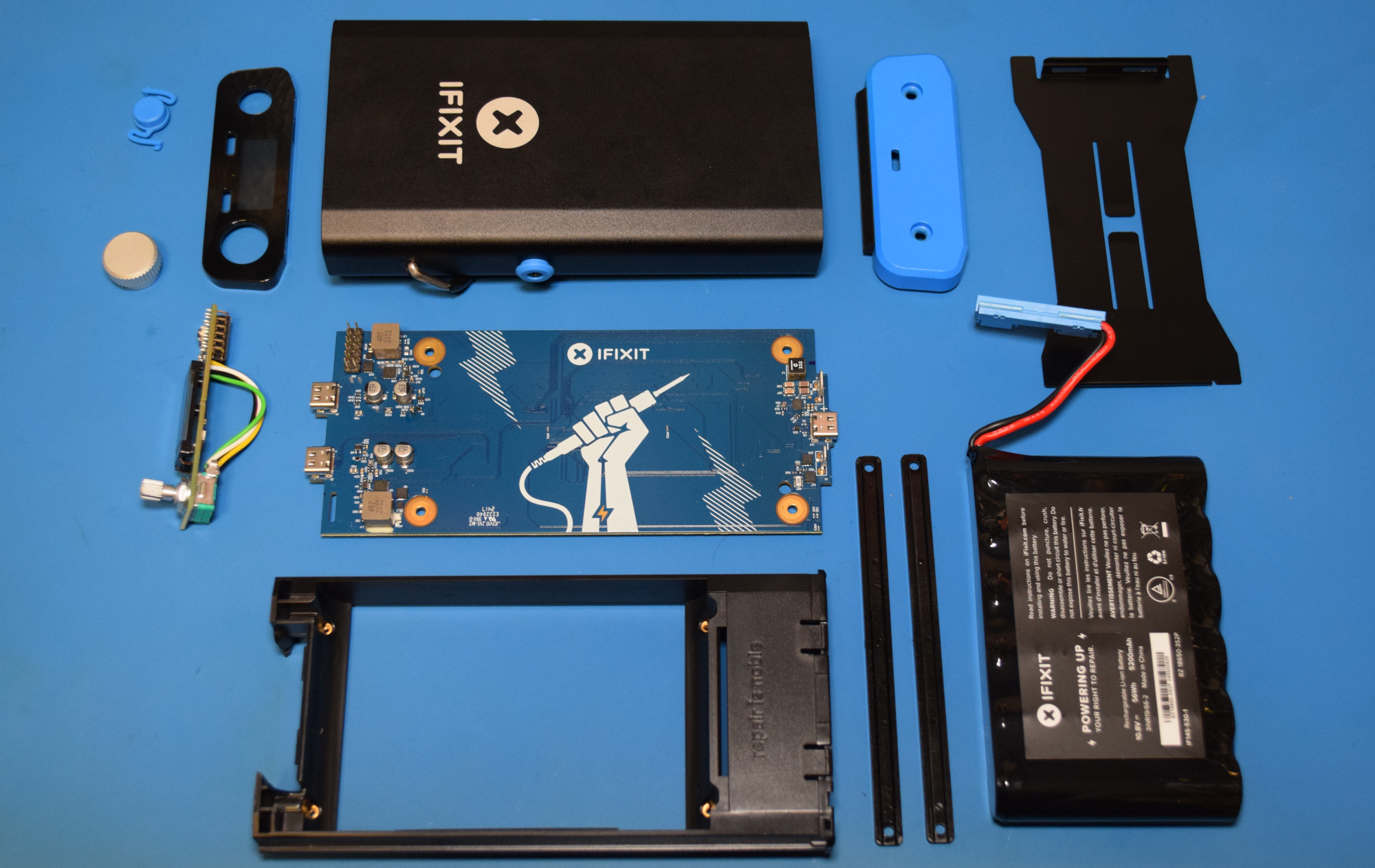
Before we get too much farther, I should clarify that the FixHub is technically two separate devices. Officially iFixit calls the combo a “Portable Soldering System” in their documentation, which is made up of the Smart Soldering Iron and the Portable Power Station. While they are designed to work best when combined, both are fully capable of working independently of each other.
Smart Soldering Iron
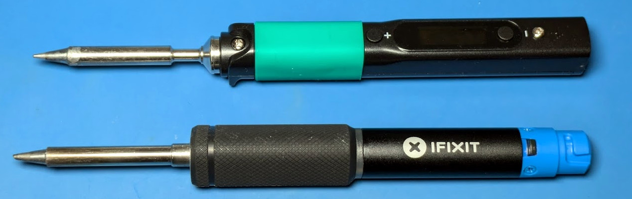
The star of the show is, of course, the Smart Soldering Iron. It’s a 100 watt iron that comes up to operating temperature in under five seconds and can work with any suitably beefy USB-C Power Delivery source. The size and general proportions of the iron are very close to the Pinecil V2, though the grip is larger and considerably more comfortable to hold. The biggest difference between the two however is the absence of a display or configuration buttons. According to iFixit, most users don’t change their settings enough to justify putting the interface on the iron itself. That doesn’t mean you can’t tweak the iron’s settings when used in this stand-alone configuration, but we’ll get back to that in a minute.
The only control on the iron is a slide switch on the tail end that cuts power to the heating element. I like this arrangement a lot more than the software solution used on irons like the Pinecil. The click of the switch just feels more reliable than having to hold down a button and hoping the iron’s firmware understands that I want to turn the thing off and not adjust some setting. Of course, this is still a “smart” iron, so naturally there’s also support for accelerometer based idle and sleep modes that you can enable.
While there’s no display, the illuminated ring behind the grip does provide a visual indicator of what the iron is doing: solid blue means it has power but the heating element is off, a pulsing blue indicates the iron is heating, and orange means it has reached the desired temperature. If you flick the heater switch off, the ring pulses purple until it cools back off and returns to blue. It’s a simple and effective system, but the visual distinction between the blue and purple isn’t great. Would love to see the ability to customize these colors in a future firmware update.
The iron has a couple of clever portability features for those who often find themselves hacking on the go. The magnetic cap can be placed over the tip even when it’s hot, which means you don’t need to wait for the iron to cool down before you pack it away in your bag. The included USB-C cable also comes with a locking collar that mates with the groves in the tail of the iron — this keeps the cable from pulling out if you’ve got yourself contorted into some weird angle, but doesn’t prevent you from using your own cable should you want.
As for the tip, it can be easily removed without tools and uses a 3.5 mm TRS plug like the Miniware TS80, although I don’t have a TS80 handy to test if the tips are actually compatible. For their part, iFixit says they plan on offering an array of styles and sizes of tips in addition to the 1.5 mm bevel that the Smart Soldering Iron ships with.
Portable Power Station
While it’s not required to use the Smart Soldering Iron, for the best experience, you’ll want to spring for the Portable Power Station. It’s essentially a 5,200 mAh battery bank capable of powering devices at 100 W, with a single USB-C port on the back for charging and two on the front for whatever devices you want to plug into it.
The trick is, once the Station detects you’ve plugged a Smart Soldering Iron into it, you’re given the ability to configure it via the OLED screen and rotary encoder on the front of the device. There’s even support for connecting a pair of Smart Soldering Irons to the Station, each with its own independent configuration. Though in that case, both would have to share the total 100 W output.
Assuming a single Smart Soldering Iron, iFixit says you should expect to get up to eight hours of runtime from the Portable Power Station. Of course there are a lot of variables involved, so your mileage may vary. If you’re spending most of your time at the bench, you can keep the rear USB-C port connected to a Power Delivery charger and use it more or less like a traditional station.
The Internet of Irons
Plugging the Smart Soldering Iron into the Power Station is the most obvious way of tweaking its various settings, but as I mentioned earlier, it’s not the only way.
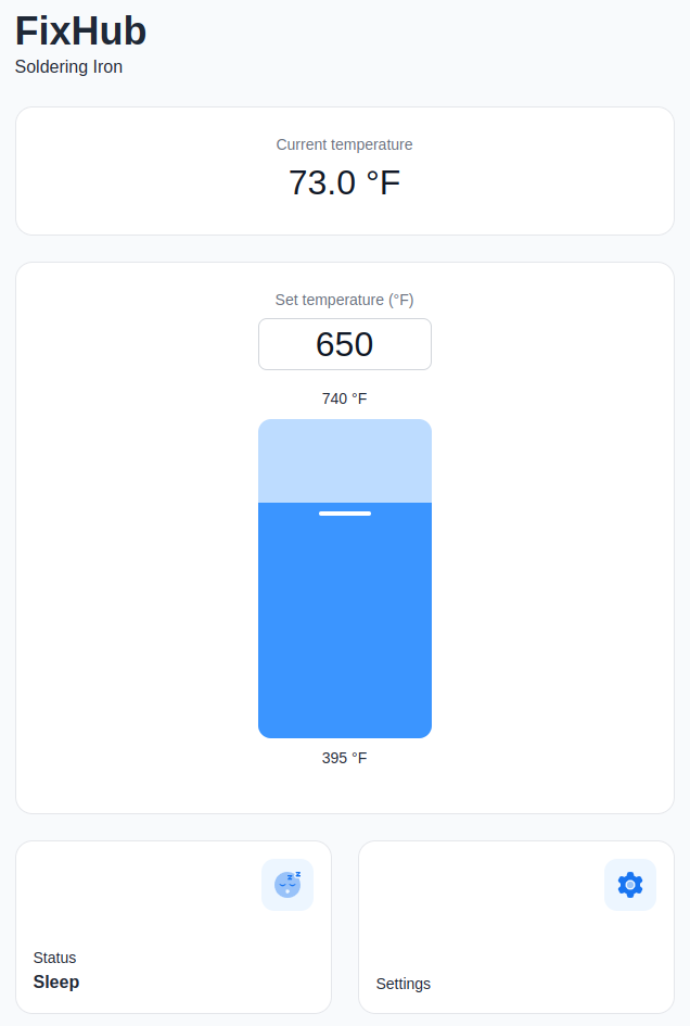
Maybe you don’t want to buy the Station, or you left it at home. In either event, you can simply plug the iron into your computer and configure it via WebSerial.
You’ll need a browser based on Chrome to pull this trick off, as Mozilla has decided (at least, for now) to not include the capability in Firefox. In testing, it worked perfectly on both my Linux desktop and Chromebook.
Unfortunately, plugging the iron into your phone won’t work, as the mobile version of Chrome does not currently support WebSerial. But given the vertical layout of the interface and the big touch-friendly buttons, I can only assume that iFixit is either banking on this changing soon or has a workaround in mind. Being able to plug the iron into your phone for a quick settings tweak would be incredibly handy, so hopefully it will happen one way or another.
The WebSerial interface not only gives you access to all the same settings as plugging the iron into the Power Station does, but it also serves as the mechanism for updating the firmware on the iron.
Incidentally, the Power Station has it’s own nearly identical WebSerial interface. Primarily this would be used for upgrading the firmware, but it’s not hard to imagine that some users would prefer being able to change their settings on the big screen rather than having to squint at an OLED not much larger than their thumbnail.
Solder At Your Command
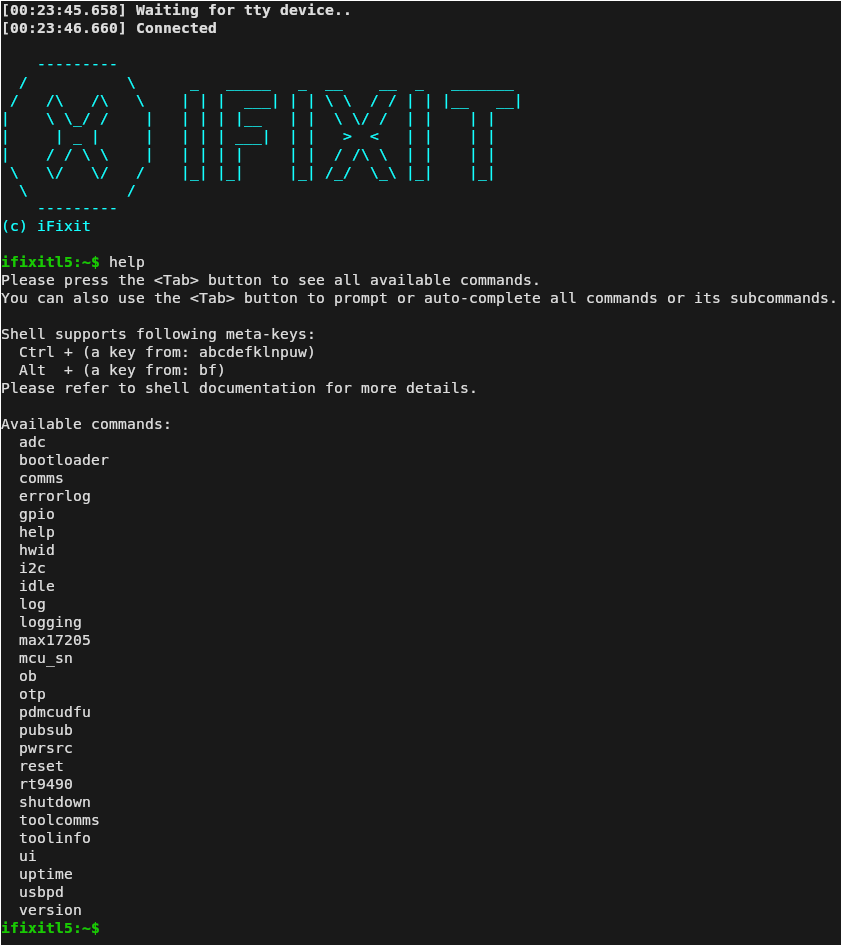
But wait! I hear those gears turning in your head. If the Smart Soldering Iron into the Power Station both feature WebSerial interfaces that let you play around with their settings, does that mean they might also offer a traditional serial interface for you to poke around in?
Hell yeah they do!
There was no mention of this terminal interface in any of the documentation I received from iFixit, but thanks to the built-in help function and tab completion, I was able to make my way around the various tools and functions. I never knew how badly I yearned to adjust the temperature on my soldering station from the command line before this moment. There’s clearly a lot of potential here, and I’m really looking forward to seeing what the community can come up given this level of control.
A Look Under the Hood
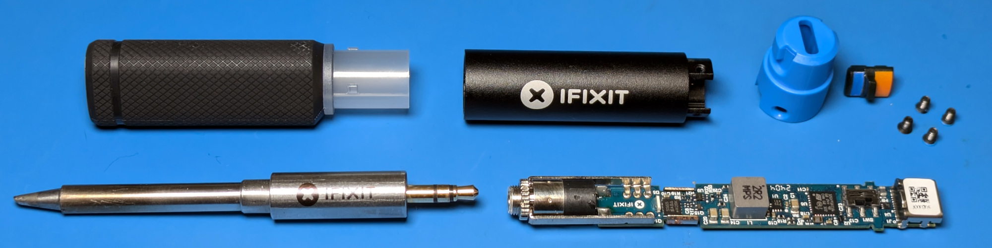
iFixit offered to give me a peek at the in-development repair guides for the Smart Soldering Iron and the Power Station, but I passed. For one thing, there’s no doubt in my mind that the finished product is going to be phenomenally detailed. Just look at any of their in-house guides, and you’ll know what to expect. But more to the point, I wanted to see how hard it would be to take the two devices apart without any guidance.
I’m happy to report that the iron and its base station are some of the most easily dissembled devices I’ve ever come across. No glue, weird tape, or hidden fasteners. No little plastic tabs that break if you look at them the wrong way. Just two pieces of hardware that were designed and assembled in a logical enough way that you only need to look at them to understand how it all goes together.
Of course, this should come as no surprise. Imagine the mud that would have been slung had iFixit had dropped the ball here. You can’t very well campaign for repairability if you don’t hold your own products to the same standards you do for everyone else. Presumably they designed the Smart Soldering Iron and the Power Station to hit a perfect ten by their published standards, and from what I’ve seen, they nailed it.
I also got a look at the schematics, exploded diagrams, and parts list for both products. Like the repair guides, these won’t be made public until the hardware ships in October. But don’t worry, this isn’t some crowdsource bait-and-switch. They’ve got the goods, and it’s all very impressive.
Now to be clear, we’re not talking open source hardware here. Don’t expect to pull Gerbers from a GitHub repo so you can crank out your own Power Station. But the documentation they’re providing is remarkable for a consumer device. The schematics especially — they’re filled with all sorts of notes in the margins from the engineers which were fascinating to go through.
Investing in the Future
If I’ve not made it abundantly clear so far, iFixit really blew me away with the Portable Soldering System. I knew they would put a solid effort into the product from their reputation alone, but even still, I wasn’t expecting the hardware and software to be this polished. iFixit didn’t just raise the bar, they sent it into orbit.
But all this comes at a price. Literally. The Smart Soldering Iron alone will set you back $79.95, and if you want to get the Power Station along with it, the combo comes in at $249.95. You could get a nice soldering station from Weller or Hakko for half the price. Then again, it’s hard to compare what iFixit is offering here to anything else on the market.
In the end, this is one of those times when you’ve got to decide what’s really important to you. If you just want a quality soldering station, there are cheaper options that will meet all of your needs and then some. But if you want to support a company that’s working to change the status quo, sometimes you’ve got to reach a little deeper into those pockets.
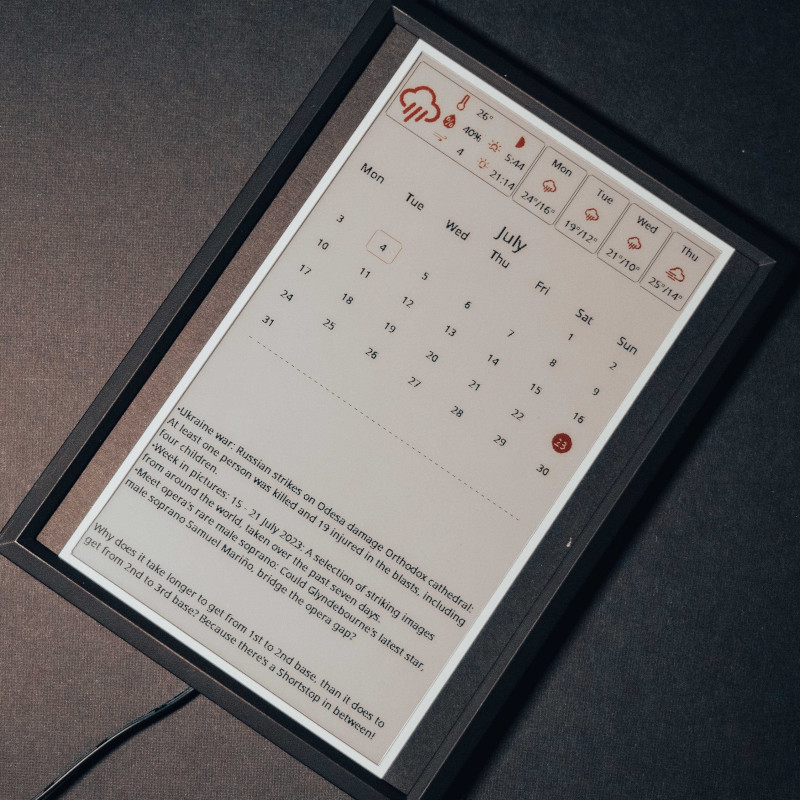
The e-paper “dashboard” is something we’ve seen plenty of times here at Hackaday. Use it to show your daily schedule, the news, weather, maybe the latest posts from your favorite hardware hacking website. Any information source that doesn’t need to be updated more than every hour or so is a perfect candidate. All you’ve got to do is write the necessary code to pull down said data and turn it into a visually attractive display.
Well, that last part isn’t always so easy. There are plenty of folks who have no problem cobbling together a Raspberry Pi and one of the commercially available e-paper modules, but writing the software to turn it into a useful information center is another story entirely. Luckily, Inkycal is here to help.
This open source project uses Python to pull information from a wide variety of sources and turns it into an e-paper friendly dashboard. It works with Waveshare displays ranging from 4.2 inches all the way up to the massive 12 inch tricolor panels. While it could theoretically be deployed on any operating system running a modern version of Python, it’s primarily developed to be run under Linux and on the Raspberry Pi. All of the versions of the Pi are supported, so no need to spring for the latest and greatest model. In fact, the notoriously pokey Raspberry Pi Zero is their recommended platform thanks to its low power consumption.
With Inkycal on the Pi — they even provide a pre-configured SD card image — and the e-paper display hooked up, all you need to do is pick which sources you want to use from the web-based configuration page. Look ma, no code!
Hackaday readers are likely the kind of folks that have a favorite keyboard, so you can probably imagine how devastating it would be to find out that the board you’ve sworn by for years is going out of production. Even worse, the board has some internal gremlins that show up after a few years of use, so functional ones in the second-hand market are becoming increasingly rare. So what do you do?
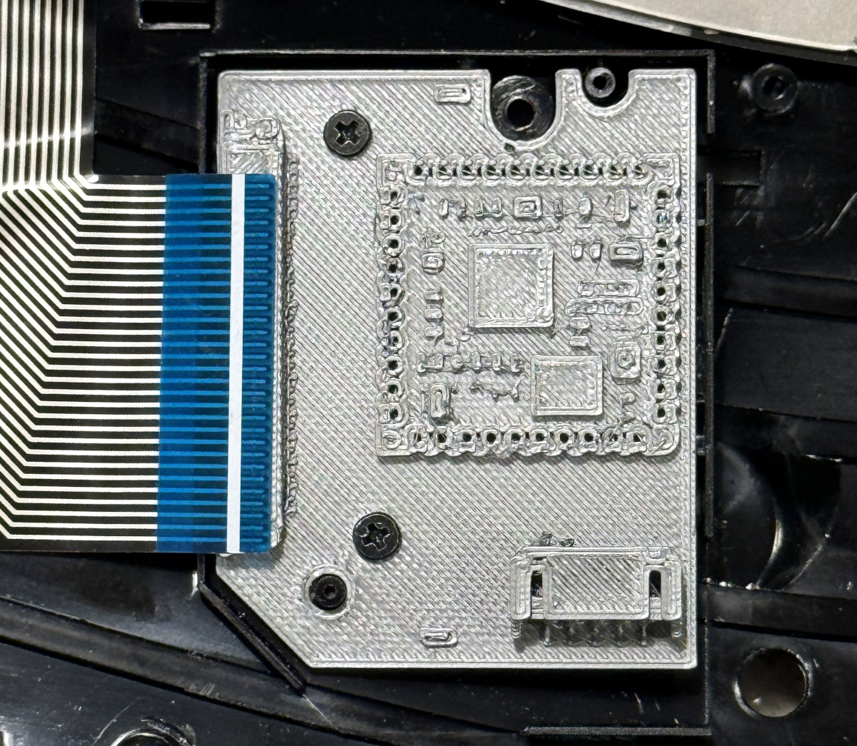
This is the position [TechBeret] recently found himself in with his beloved Sculpt keyboard. When Microsoft decided to step back from the peripheral market last year, he started looking at alternatives. Finding none of them appealing, he decided instead to breathe new life into the ergonomic keyboard with the RP2040. Every aspect of the resurrection is covered in a phenomenally detailed write-up on his blog, making this a valuable case study in modernizing peripherals with the popular microcontroller.
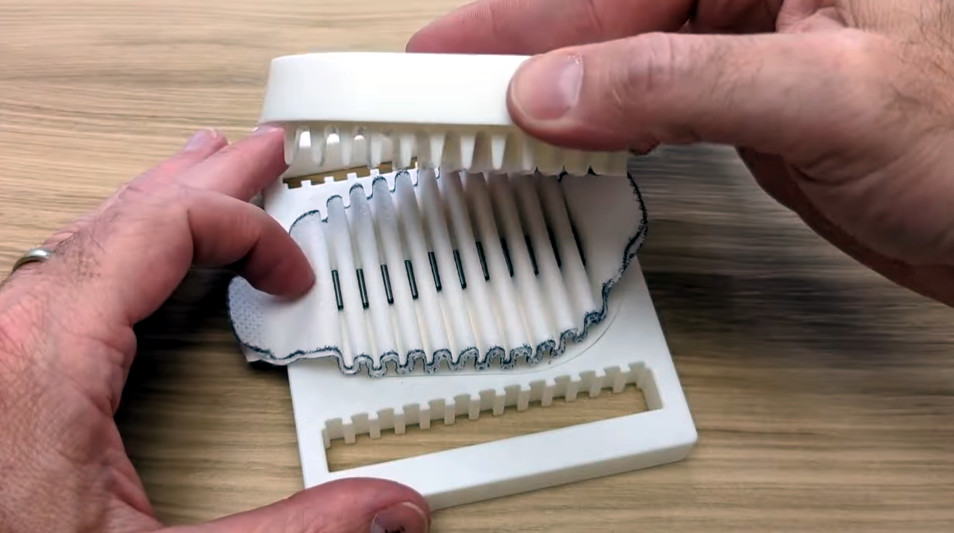
According to [TechBeret], the biggest problem with the Sculpt was its wonky wireless hardware. It was bad enough that the board was permanently paired to its USB dongle, but apparently, the RF side of things would degrade over time, leading to an ever shorter range. So he decided the best course of action was to simply give the board a brain transplant. Since he didn’t really want it to be wireless anyway, he figured it wouldn’t be too difficult to create a replacement PCB that reads the keyboard matrix and speaks USB Human Interface Device (HID).
Checking the fit with a 3D-printed PCB
In fact, he was able to find a couple of projects that did that exactly. Instead of copying them, he took them as inspiration to help direct his own effort. His primary goal was to develop a drop-in replacement for the original PCB — specifically, he didn’t want to have to take a Dremel to his keyboard just to get it working again. He also wanted to use components he knew would be available for the foreseeable future, as well as bring USB-C support to the party. Finally, he didn’t want to get bogged down in writing code, so the replacement board had to be able to run the popular QMK firmware.
By his own admission, [TechBeret] is no expert in such matters. But that makes the write-up all the more compelling. Rather than seeing a perfect result on the first attempt, we get to learn along through his trials and tribulations. Even if you’ve done this kind of thing before, we bet you’ll pick up some interesting tricks along the way. We particularly liked his tip about test-fitting your PCB by exporting it as a STEP file and 3D printing a replica.
It might seem like a lot of work to save a keyboard, but then, those who’ve come to love it — like our very own [Lewin Day] — will tell you the Sculpt isn’t just any keyboard. QMK might even make it better.
While it’s the ideal choice for mass production, injection molding is simply no good for prototyping. The molds are expensive and time-consuming make, so unless you’ve got the funding to burn tens of thousands of dollars on producing new ones each time you make a tweak to your design, they’re the kind of thing you don’t want to have made until you’re absolutely sure everything is dialed in and ready. So how do you get to that point without breaking the bank?
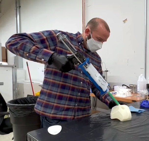
That’s not always an easy question, but if you’re working with silicone parts, the team at OpenAeros thinks they might have a solution for you. As demonstrated through their OpenRespirator project, the team has developed a method of 3D printing single-use molds suitable for large silicone parts that they’re calling Digital-to-Silicone (D2S).
In the video below, [Aaron] and [Jon] explain that they started off by simply printing injection molds in the traditional style. This worked, but the molds can get quite complex, and the time and effort necessary to design and print them wasn’t a great fit for their iterative development cycle. They wanted to be able to do from design to prototype in a day, not a week.
Eventually they realized that if they printed the mold out of a water-soluble filament, they could simplify its design greatly. They’ve documented the design process in detail, but the short version is that you essentially subtract the 3D model of the design you want to produce from a solid shape in your CAD package, and add a few holes for injecting the silicone. Once the silicone has cured, the mold can be dissolved away in warm water to reveal the finished part.
They then took this concept a step further. Thanks to the multi-material capabilities offered by some of the latest 3D printers, it’s possible to print structures within the mold. Once the silicone is injected, these structures can become part of the finished part. For the OpenRespirator, this lets them add PETG stiffening rings around where the filters to snap into the silicone mask body.
As an added bonus, the video also goes over their method of prototyping pleated filters with 3D printed forms. After inserting the filter media, snap-in arms push it down into the valleys of the form to create the pleats. These are held in place with the addition of small metal rods that are attracted to the magnets embedded into the form. Once the top and bottom of the form have been closed over the filter, silicone is injected to create a ring around the filter and lock everything into place.
We often think of 3D printing as ideal for prototyping, but usually in a very direct and obvious way. You print out a part to see if it works the way you want, and then take the design and have it made out of something stronger. But this presentation from OpenAeros shows just how versatile the technology can be. With even a half-way decent desktop printer, the potential time and cost savings can be enormous. Something to keep in mind should one of your side projects turn into something bigger.
If you’ve been reading Hackaday for awhile, you’ll know we’re big fans of OpenSCAD around these parts. There’s a number of reasons it’s a tool we often reach for, but certainly one of the most important ones is its parametric nature. Since you’re already describing the object you want to generate with code and variables, it’s easy to do things like generate an arbitrary number of cloned objects by using a for loop.
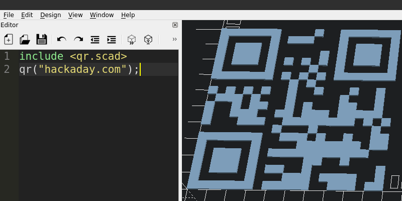
There are a number of fantastic OpenSCAD libraries that explore this blurred line between code and physical objects, and one that recently caught our eye is scadqr from [xypwn]. The description says it lets you “Effortlessly generate QR codes directly in OpenSCAD”, and after playing around with it for a bit, we have to agree.
How effortlessly are we talking about? Take a look:
Yeah, that’s pretty damn easy. Even better, there’s no alphabet soup of libraries or APIs going on behind the scenes here. It’s just a single file you include in your OpenSCAD script. In fact, you don’t even need to go that far. As [xypwn] explains, the source for the library itself is just the one file, so you could just copy its code right into your project if you didn’t want to have to pull it in as an include. That could be especially handy if you’re deploying this code somewhere that doesn’t let you pull in external files, like Thingiverse’s Customizer.
Now, there’s all sorts of reasons you might want to create a QR code from within OpenSCAD. But one of first ones that popped into our heads is for the purposes of part identification. Forget simple version numbers, this library would let you physically embed all sorts of ancillary data into your printed components, like who rendered them and at what time. Or perhaps each printed part in an assembly could have a unique QR code that pointed to its respective page in your online documentation.
Got any interesting ideas? Let us know in the comments.
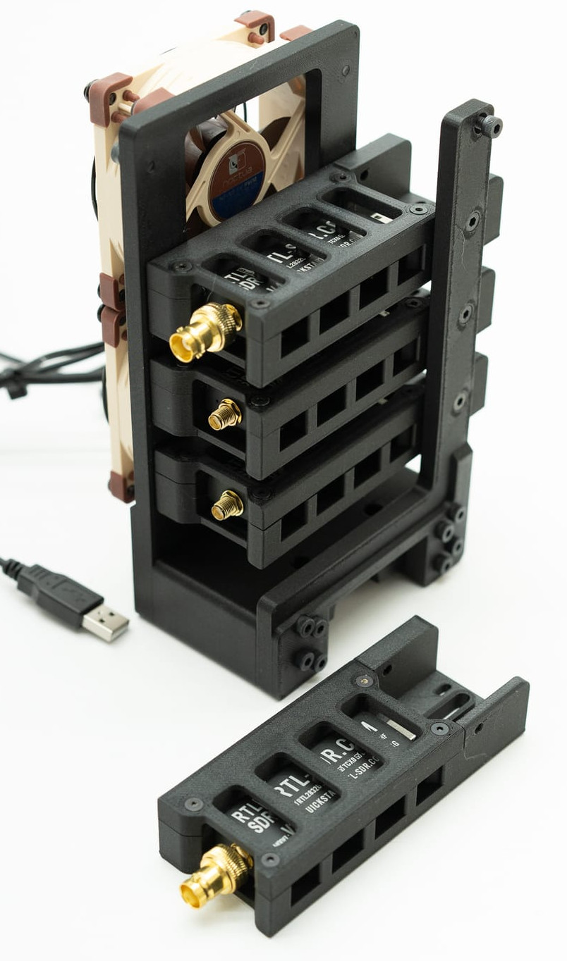
With as cheap and versatile as RTL-SDR devices are, it’s a good idea to have a couple of them on hand for some rainy day hacking. In fact, depending on what signals you’re trying to sniff out of the air, you may need multiple interfaces anyway. Once you’ve amassed this arsenal of software defined radios, you may find yourself needing a way to transport and deploy them. Luckily, [Jay Doscher] has you covered.
His latest creation, the SDR SOLO, is a modular system for mounting RTL-SDRs. Each dongle is encased in its own 3D printed frame, which not only protects it, but makes it easy to attach to the base unit. To keep the notoriously toasty radios cool, each frame has been designed to maximize airflow. You can even mount a pair of 80 mm fans to the bottom of the stack to really get the air moving. The current design is based around the RTL-SDR Blog V4, but could easily be adapted to your dongle of choice.
In addition to the row of SDR dongles, the rig also includes a powered USB hub. Each radio connects to the hub via a short USB cable, which means that you’ll only need a single USB cable running back to your computer. There’s also various mounts and adapters for attaching antennas to the system. Stick it all on the end of a tripod, and you’ve got a mobile radio monitoring system that’ll be the envy of the hackerspace.
As the name of the channel implies, [BuyItFixIt] likes to pick up cheap gadgets that are listed as broken and try to repair them. It’s a pastime we imagine many Hackaday readers can appreciate, because even if you can’t get a particular device working, you’re sure to at least learn something useful along the way.
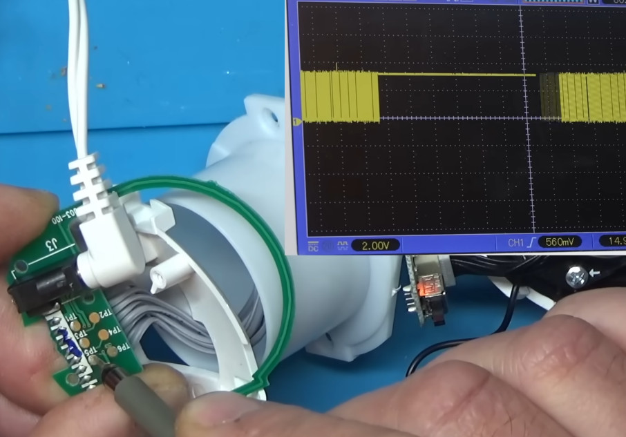
But after recently tackling a VTech video baby monitor from eBay, [BuyItFixIt] manages to do both. He starts by opening up the device and going through some general electronics troubleshooting steps. The basics are very much worth following along with if you’ve ever wondered how to approach a repair when you don’t know what the problem is. He checks voltages, makes sure various components are in spec, determines if the chips are talking to each other with the oscilloscope, and even pulls out the thermal camera to see if anything is heating up. But nothing seems out of the ordinary.
The scope uncovers some serial data.
While poking around with the oscilloscope, however, he did notice what looked like the output of a serial debug port. Sure enough, when connected to a USB serial adapter, the camera’s embedded Linux operating system started dumping status messages into the terminal. But before it got too far along in the boot process, it crashed with a file I/O error — which explains why the hardware all seemed to check out fine.
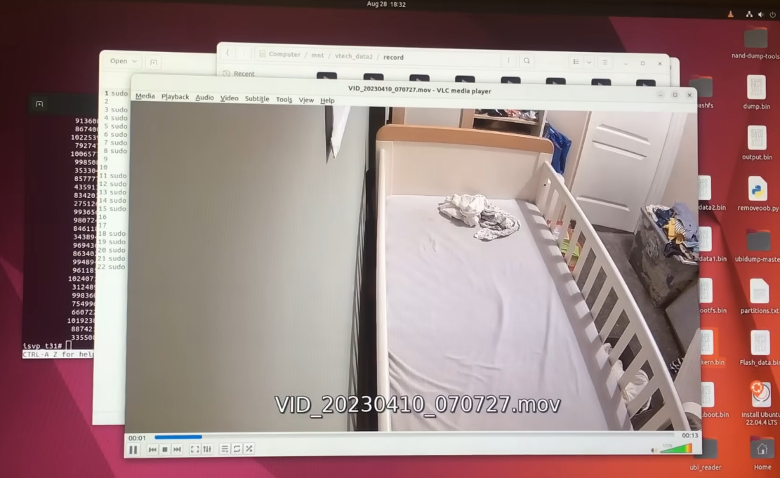
Now that [BuyItFixIt] knew it was a software issue, he started using the tools built into the camera’s bootloader to explore the contents of the device’s flash chip. He uncovered the usual embedded Linux directories, but when he peeked into one of the partitions labeled Vtech_data2, he got a bit of a shock: the device seemed to be holding dozens of videos. This is particularly surprising considering the camera is designed to stream video to the parent unit, and the fact that it could record video internally was never mentioned in the documentation.
While copying the chip’s contents over serial would have been possible, [BuyItFixIt] instead pulled it out and physically dumped the whole thing with a reader. With a bit of Linux-fu, he’s able to mount the chip dump and confirm that the videos in question are of the previous owner’s infant. Yikes. Of course, he promptly deleted the files once he realized what the camera had stored, but it makes us wonder how many cameras like these are holding private video files waiting for a bad actor to uncover them. This is an important reminder of the inherent dangers of tossing away “broken” smart devices.
Dozens of videos featuring the parent and child were still stored on the device.
As for the repair itself, [BuyItFixIt] reasoned that some file — maybe the database of videos — must have been corrupted on the chip, so he took the nuclear option and wiped it all out. He had to use the bootloader commands to recreate the partition table, but once that was done, the firmware seemed to understand that it had been returned to a factory state and was finally able to boot up normally. He’s documented the commands he used to get it back up and running in the hopes he can help out somebody else with a similarly ailing camera.
We can never get enough of this sort of firmware hacking, and the fact that this particular bout opened up with a great real-world example of hardware diagnosis makes it all the better. This is a long video, but one that’s well worth your time to check out. If you’d like to see more repairs from [BuyItFixIt], we’ve got you covered.
It might seem like the days of MS-DOS were a lifetime ago because…well, they basically were. Version 6.22 of the venerable operating system, the last standalone release, came out back in 1994. That makes even the most recent version officially 30 years old. A lot has changed in the computing world since that time, so naturally trying to run such an ancient OS on even a half-way modern machine would be a waste of time. Right?
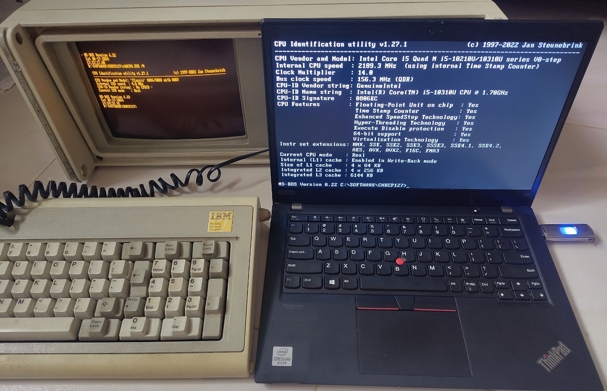
As it turns out, getting MS-DOS 6.22 running on a modern computer isn’t nearly as hard as you’d think. In fact, it works pretty much perfectly. Assuming, that is, you pick the right machine. [Yeo Kheng Meng] recently wrote in to share his experiments with running the final DOS release on his Intel-powered ThinkPad X13 from 2020, and the results are surprising to say the least.
To be clear, we’re not talking about some patched version of DOS here. There’s no emulator at work either. Granted [Yeo] did embrace a few modern conveniences, such as using a USB floppy drive emulator to load the disk images instead of fiddling with actual floppies, and installing DOS onto an external drive so as not to clobber his actual OS on the internal NVME drive. But other than that, the installation of DOS on the ThinkPad went along just as it would have in the 1990s.
IBM’s 1984 luggable running the same OS as a modern ThinkPad
It’s impressive enough that MS-DOS can still be installed on such a modern machine. But what’s really surprising is how well it all works. [Yeo] reports that the bulk of the ThinkPad’s hardware worked as expected, although he did have to pull in some modern open source drivers such as SBEMU, which makes DOS think the laptop’s Intel HD audio chip is an old school Sound Blaster card. He was even able to get several different Thunderbolt-connected Gigabit Ethernet adapters working.
Not all of the DOS benchmark tools [Yeo] tried on the machine would actually run, but as you might imagine, the ones that did reported some fairly spectacular results. After all, a machine with specs like this would have been the stuff of science fiction when those tools were written.
So how is this all possible? [Yeo] notes that this is one of the final Lenovo laptops to support “Legacy BIOS” mode, as everything after this point is pure UEFI. This particular machine also features a “Thunderbolt BIOS Assist Mode” which makes connected devices seem like standard PCI cards.
In the end, the experiment shows that Intel and Lenovo have done an incredible job of maintaining backwards compatibility with their respective hardware. While it seems like this is the end of the road for your average consumer computer due to issues such as the UEFI switch over, don’t worry. You’ll still be able to scratch that retro itch with the right hardware.