Reservoir Sampling, or How to Sample Sets of Unknown Size
Selecting a random sample from a set is simple. But what about selecting a fair random sample from a set of unknown or indeterminate size? That’s where reservoir sampling comes in, and [Sam Rose] has a beautifully-illustrated, interactive guide to how reservoir sampling works. As far as methods go, it’s as elegant as it is simple, and particularly suited to fairly sampling dynamic datasets like sipping from a firehose of log events.
While reservoir sampling is simple in principle it’s not entirely intuitive to everyone. That’s what makes [Sam]’s interactive essay so helpful; he first articulates the problem before presenting the solution in a way that makes it almost self-evident.
[Sam] uses an imaginary deck of cards to illustrate the problem. If one is being dealt cards one at a time from a deck of unknown size (there could be ten cards, or a million), how can one choose a single card in a way that gives each an equal chance of having been selected? Without collecting them all first?
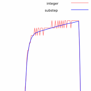
In a nutshell, the solution is to make a decision every time a new card arrives: hold onto the current card, or replace it with the new one. Each new card is given a 1/n chance of becoming held, where n is the number of cards we’ve seen so far. That’s all it takes. No matter when the dealer stops dealing, each card that has been seen will have had an equal chance of ending up the one selected.
There are a few variations which [Sam] also covers, and practical ways of applying it to log collection, so check it out for yourself.
If [Sam]’s knack for illustrating concepts in an interactive way is your jam, we have one more to point out. Our own Al Williams wrote a piece on Turing machines; the original “universal machine” being a theoretical device with a read/write head and infinite paper tape. A wonderful companion to that article is [Sam]’s piece illustrating exactly how such a Turing machines would work in an interactive way.