For most of us, mirrors are something we buy instead of build. However, [Unnecessary Automation] wanted to craft mirrors of his own for a custom telescope build. As it turns out, producing optically-useful mirrors is not exactly easy.
For the telescope build in question, [Unnecessary Automation] needed a concave mirror. Trying to get that sort of shape with glass can be difficult. However, there’s such a thing as a “liquid mirror” where spinning fluid forms into a parabolic-like shape. Thus came the idea to spin liquid resin during curing to try and create a mirror with the right shape.
That didn’t quite work, but it inspired a more advanced setup where a spinning bowl and dense glycerine fluid was used to craft a silicone mold with a convex shape. This could then be used to produce a resin-based mirror in a relatively stationary fashion. From there, it was just necessary to plate a shiny metal layer on to the final part to create the mirror effect. Unfortunately, the end result was too messy to use as a viable telescope mirror, but we learn a lot about what didn’t work along the way.
The video is a great journey of trial and error. Sometimes, figuring out how to do something is the fun part of a project, even if you don’t always succeed. If you’ve got ideas on how to successfully spin cast a quality mirror, drop them in the comments below. We’ve seen others explore mirror making techniques before, too.
You can buy all sorts of RC cars off the shelf, but doing so won’t teach you a whole lot. Alternatively, you could follow [TRDB]’s example, and design your own from scratch.
The Lizard, as it is known, is a fun little RC car. It’s got a vaguely Formula 1-inspired aesthetic, and looks fetching with the aid of two-tone 3D printed parts. It’s designed for speed and handling, with a rear-wheel-drive layout and sprung suspension at all four corners to soak up the bumps. The majority of the vehicle is 3D printed in PETG, including the body and the gearbox and differential. However, some suspension components are made in TPU for greater flexibility and resistance to impact. [TRDB] specified commercial off-the-shelf wheels to provide good grip that couldn’t easily be achieved with 3D-printed tires. An ESP32 is responsible for receiving commands from [TRDB’s] custom RC controller running the same microcontroller. It sends commands to the speed controller that runs the Lizard’s brushed DC motor from a 3S lithium-polymer battery.
The final product looks sleek and handles well. It also achieved a GPS-verified top speed of 48 km/h as per [TRDB’s] testing. We’ve seen some other great DIY RC cars over the years, too, like this example that focuses on performance fundamentals. Video after the break.
The Radio Shack TRS-80 was a much-loved machine across America. However, one thing it lacked was MIDI. That’s not so strange given the era it was released in, of course. Nevertheless, [Michael Wessel] has seen fit to correct this by creating the MIDI/80—a soundcard and MIDI interface for this old-school beast.
The core of the build is a BluePill STM32F103C8T6 microcontroller, running at a mighty 75 MHz. Plugged into the TRS-80s expansion port, the microcontroller is responsible for talking to the computer and translating incoming and outgoing MIDI signals as needed. Naturally, you can equip it with full-size classic DIN sockets for MIDI IN and MIDI OUT using an Adafruit breakout module. None of that MIDI Thru nonsense, though, that just makes people uncomfortable. The card is fully capable of reproducing General MIDI sounds, too, either via plugging in a Waveblaster sound module to the relevant header, or by hooking up a Roland Sound Canvas or similar to the MIDI/80s MIDI Out socket. Software-wise, there’s already a whole MIDI ecosystem developing around this new hardware. There’s a TRS-80 drum tracker and a synthesizer program, all with demo songs included. Compatibility wise, The MIDI/80 works with the TRS-80 Model I, III, and 4.
Does this mean the TRS-80 will become a new darling of the tracker and chiptune communities? We can only hope so! Meanwhile, if you want more background on this famous machine, we’ve looked into that, too. Video after the break.
If you haven’t played the Metal Gear games, the Codec has been modelled somewhat like an advanced walkie talkie at times, but has often been kept off-screen. Thus, [3DSage] had a great deal of creative latitude to create a realistic-feeling Codec device that provided voice communications and some simple imagery display.
The resulting build relies on an RP2040 microcontroller to run the show. It’s paired with an MPU6050 3-axis gyroscope and accelerometer for motion control of the device’s functionality, and features a small LCD screen to mimic the display in the games. A kids walkie-talkie kit was leveraged for audio communication, but kitted out with a better microphone than standard. Power is via a rechargeable 9V battery, which is really a lithium-ion and USB charging board packed into the familiar 9V form factor.
Where the build really shines, though, is the aesthetic. [3DSage] managed to capture the military-like look and feel as well as authentically recreate the graphics from the games on the screen. The simulated noise on the display is particularly charming. Beyond that, the 3D-printed enclosures leverage texture and multi-color printing really well to nail the fit and finish.
Ultimately, the Codec isn’t much more than a glorified walkie talkie. Even still, [3DSage] was able to create an impressive prop that actually does most of what the device can do in game. If you’ve ever coveted a PipBoy or tricorder, this is one project you’ll be able to appreciate.
Portal 2 is mostly known as the successful sequel to Valve’s weird physics platformer, Portal. It’s not really known for being a webserver. That might change, though, given the hard work of [PortalRunner].
Quite literally, [PortalRunner] hacked the Source engine and Portal 2 to actually run a working HTTP web server. That required setting up the code to implement a TCP network socket that was suitable for web traffic, since the engine primarily functions with UDP sockets for multiplayer use. This was achieved with a feature initially put in the Source engine for server management in the Left 4 Dead games. From there, the game engine just had to be set up to reply to HTTP requests on that socket with the proper responses a visiting browser expects. If the game engine responds to a browser’s connection request with a bunch of HTML, that’s what the browser will display. Bam! You’ve got a web server running in Portal 2.
From there, [PortalRunner] went further, setting things up so that the status of in-game objects effects the HTML served up to visiting web browsers. Move objects in the game, and the served web page changes. It’s pretty fun, and the complexity and features [PortalRunner] implements only get more advanced from there. When he gets into stacking companion cubes to write HTML in visual form, you’ll want to applaud the Minecraftian glory of it all.
The devil is really in the details on this one, and it’s a great watch. In reality, making Portal 2 into a simple web server is far easier than you might have thought possible. Valve’s physics masterpiece really is popular with hackers; we see it popping up around here all the time. Video after the break.
A treadmill-style bed can be a great addition to a 3D printer. It allows prints to be shifted out of the build volume as printing continues, greatly increasing the size and flexibility of what you can print. But [Ivan Miranda] and [Jón Schone] had a question. Instead of making a treadmill to suit a 3D printer, what if you just built a 3D printer on top of a full-size treadmill?
The duo sourced a piece of real gym equipment for this build. They then set about building a large-scale 3D printer on top of this platform. The linear rails were first mounted on to the treadmill’s frame, followed by a gantry for the print head itself and mounts for the necessary stepper motors. The printer also gained a custom extra-large extruder to ensure a satisfactory print speed that was suitable for the scale of the machine. From there, it was largely a case of fitting modules and running cables to complete the printer.
Soon enough, the machine was printing hot plastic on the treadmill surface, thereby greatly expanding the usable print volume. It’s a little tricky to wrap your head around at first, but when you see it in action, it’s easy to see the utility of a build like this, particularly at large scale. [Ivan] demonstrated this by printing a massive girder over two meters long.
[panjanek] grabbed WS2812B addressable LEDs for this project, assembling them into a 32 x 32 matrix that fits perfectly inside an off-the-shelf Ikea picture frame. The matrix is hooked up to an ESP8266 microcontroller, which acts as the brains of the operation. The WiFi-enabled microcontroller hosts its own web interface, with which the project can be controlled. Upon opening the page, it’s possible to upload a GIF file that will be displayed as an animation on the matrix itself. It’s also possible to stream UDP packets of bitmap data to the device to send real-time animations over a network.
It’s a neat build, and one that answers any questions of what you might display on your LED matrix when you’re finished assembling it. Code is on Github if you fancy implementing the GIF features in your own work. We’ve featured some unexpected LED matrix builds of late, like this innovative device for the M.2 slot. Meanwhile, if you’re cooking up your own creative LED builds, don’t hesitate to let us know on the tipsline!
Last week, we examined a Doom port for the venerable Atari ST. As is so often the way with this thing, one netted another, and [Steve] wrote in to inform us about a different version under the name DOOM8088ST.
The port is so named because it’s based on Doom8088, which was originally written for DOS machines running Intel 8088 or 286 CPUs. Both ports are the work of [FrenkelS], and aims to bring the Doom experience into the far more resource constrained environment of the Atari ST. There is only very limited sound, no saving, and it only supports Doom 1 Episode 1. Still, it’s quite recognizable as Doom!
Doom8088ST is tunable to various levels of performance, depending on what you’re running it on. Low mode (30 x 128) is suitable for stock Atari ST machines running at 8 MHz. It’s described as having “excellent” framerate and is very playable. If you’ve got an upgraded ST or Mega STe, you can try Medium (60 x 128), which has greatly improved visuals but is a lot heavier to run.
Files are on Github for those interested to run or tinker with the code. Don’t forget to check out the other port we featured last week, either, in the form of STDOOM. Video after the break.
The Commodore 64 may remain the best selling computer of all time, but it has one major flaw. It doesn’t have HDMI! That makes it a total pain to use with modern displays. Thankfully, [Side Projects Lab] has whipped up an HDMI output board to solve this concerning oversight from the original designers.
The project was inspired by work by [Copper Dragon], who whipped up a nifty RGB output board. This device worked by reading the inputs to the C64’s VIC II graphics chip, which it then used to recreate a pixel-perfect video frames to then produce a quality analog video output. [Side Projects Lab] figured the same interception technique would be useful for producing a quality HDMI output.
The result was the HD-64. It sits inside the C64 in place of the original RF modulator. It uses an interleaver socket to capture digital signals going to the VIC II. It then feeds these signals to an emulated VIC II running inside an FPGA, which creates the pixel-perfect screen representation and synthesizes the proper digital HDMI output. Meanwhile, the analog audio output from the SID chip is captured from the RF modulator’s original header, and sent out via the HDMI output as well. The default output is super-sharp, but the device can be configured to allow scanlines and anti-aliasing if that’s more to your tastes.
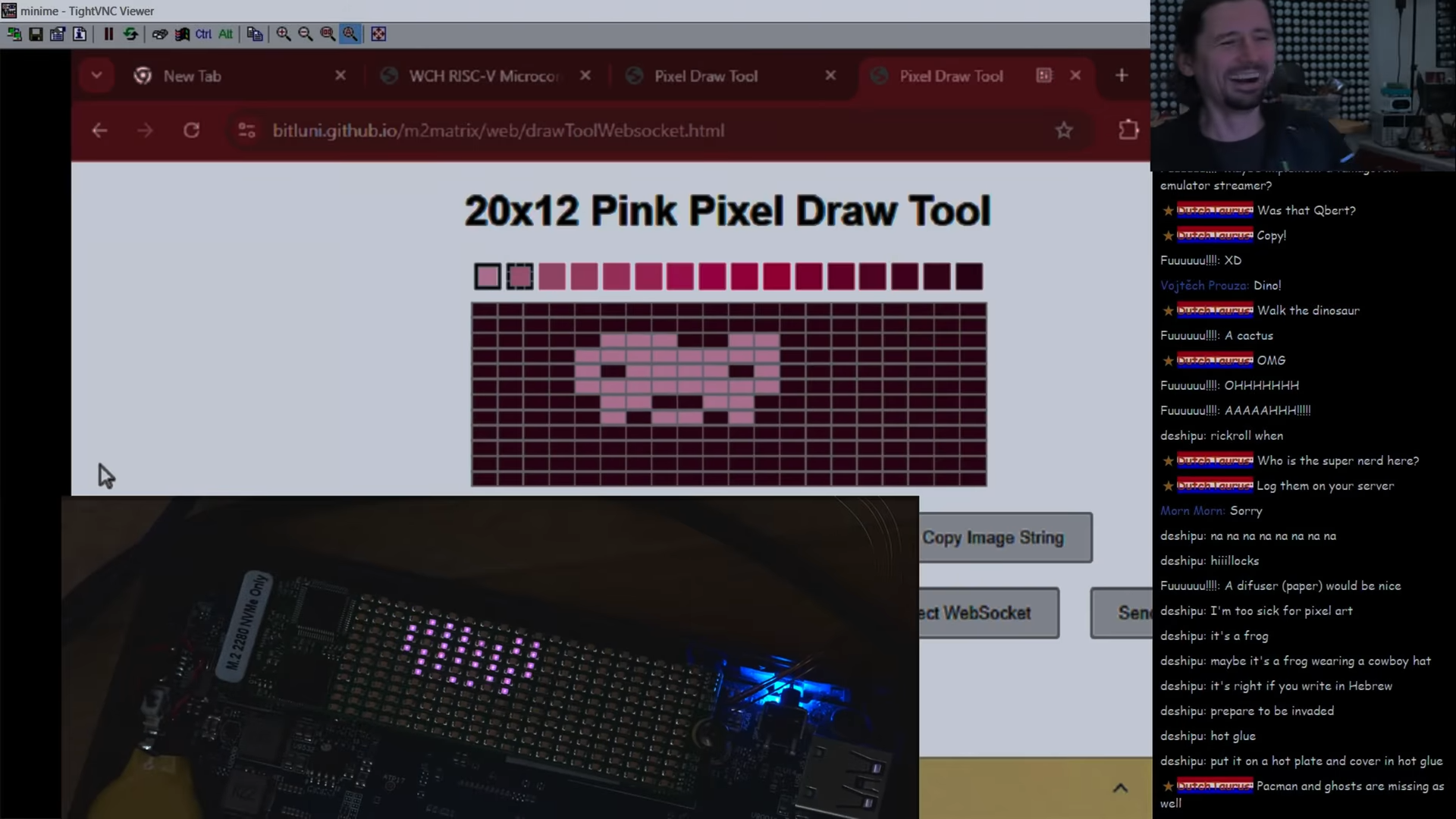
The M.2 slot is usually used for solid-state storage devices. However, [bitluni] had another fun idea for how to use the interface. He built an M.2 compatible LED matrix that adds a little light to your motherboard.
[bitluni] built a web tool for sending images to the matrix.[bitluni] noted that the M.2 interface is remarkably flexible, able to offer everything from SATA connections to USB, PCI Express, and more. For this project, he elected to rely on PCI Express communication, using a WCH CH382 chip to translate from that interface to regular old serial communication.
He then hooked up the serial interface to a CH32V208 microcontroller, which was tasked with driving a 12×20 monochrome LED matrix. Even better, he was even able to set the microcontroller up to make it programmable upon first plugging it into a machine, thanks to its bootloader supporting serial programming out of the box. Some teething issues required rework and modification, but soon enough, [bitluni] had the LEDs blinking with the best of them. He then built a web-based drawing tool that could send artwork over serial direct to the matrix.
While most of us are using our M.2 slots for more traditional devices, it’s neat to see this build leverage them for another use. We could imagine displays like this becoming a neat little add-on to a blingy computer build for those with a slot or two to spare. Meanwhile, if you want to learn more about M.2, we’ve dived into the topic before.
Typically, when we think about forming metal parts, we think about beating them with hammers, or squeezing them with big hydraulic presses. But what if magnets could do the squeezing? As it turns out—Grumman Aerospace discovered they can, several decades ago! Even better, they summed up this technique in a great educational video which we’ve placed below the break.
The video concerns the development of the Grumman EMF Torque Tube. The parts are essentially tubes with gear-like fittings mounted in either end, which are fixed with electromagnetic forming techniques instead of riveting or crimping. Right away, we’re told the key benefits—torque tubes built this way are “stronger, lighter, and more fatigue resistant” than those built with conventional techniques. Grumman used these torque tubes in such famous aircraft as the F-14 Tomcat, highlighting their performance and reliability.
Before……and after. The part is formed and the coil is destroyed.
The video goes on to explain the basics of the EMF torque tube production process. A tube is placed inside a coil, with the end fitting then installed inside. A capacitor bank dumps current through the coil to generate a strong electromagnetic field. This field is opposed by a secondary field generated by eddy currents. The two forces result in an explosive force which drives the tube inwards, gripping into the grooves of the end fitting, and destroys the coil in the process. Grumman notes that it specifically optimized a grooving profile for bonding tubes with end fittings, which maximised the strength of these EMF-produced joints.
This tip was sent in by [irox]. The video itself was posted by [Greg Benoit], who notes his father Robert Benoit was intimately involved with the development of the technique. Indeed, it was useful enough that the technology was licensed to Boeing, generating many millions of dollars for Grumman.
We feature all kinds of machining and forming techniques here, but this sort of forming isn’t something we see a lot of around these parts. Still, we’re sure someone will be Kickstarting a home EMF forming machine before the end of next week.
[Dmytro] was able to lay his hands on a InfiRay T2S+ camera. It’s a capable thermal imaging unit that comes at a cheaper price than many of its rivals. [Dmytro] decided to pull it apart to see what makes it tick, and he discovered a few interesting things along the way.
Like so much modern hardware, pulling the case apart does require some spudging and levering. Once inside, though, it comes apart in a relatively straightforward manner. Once inside, [Dmytro] notes some similarities between this camera and the Flir Lepton, another affordable thermal camera on the market. He also finds a clone of the Cypress FX2LP chip, which is used for talking USB. There’s also an Gowin FPGA inside, with [Dmytro] suspecting the gateware onboard could be modified. If so, the camera may be a candidate for running open source firmware in future.
What bothered [Dmytro] about this camera, though, was the software. When used with an Android phone, the camera demands the use of a proprietary app with with questionable permissions. It can be used on a regular computer, where it appears as a standard webcam. However, in this mode, the camera fails to self-calibrate, and the images quickly become useless. [Dmytro] worked to hack around this, by figuring out a way to trigger calibrations and run the proper image corrections manually when using the camera without the smartphone app. He also explores techniques to improve the resolution of the thermal measurements made by the camera.
We’ve seen some other neat thermal camera hacks over the years. Video after the break.
Typing can be difficult to learn at the best of times. Until you get the muscle memory down, it can be quite challenging. However, if you’ve had one or more fingers amputated, it can be even more difficult. Just reaching the keys properly can be a challenge. To help in this regard, [Roei Weiman] built some assistive typing tools for those looking for a little aid at the keyboard.
The devices were built for [Yoni], who works in tech and has two amputated fingers. [Roei] worked on many revisions to create a viable brace and extension device that would help [Yoni] type with greater accuracy and speed.
While [Roei] designed the parts for SLS 3D printing, it’s not mandatory—these can easily be produced on an FDM printer, too. For SLS users, nylon is recommended, while FDM printers will probably find best results with PETG. It may also be desirable to perform a silicone casting to add a grippier surface to some of the parts, a process we’ve explored previously.
The great thing about 3D printing is that it enables just about anyone to have a go at producing their own simple assistive aids like these. Files are on Instructables for the curious. Video after the break.
If you want a regular table saw, you’re probably best off just buying one—it’s hard to beat the economies of scale that benefit the major manufacturers. If you want a teeny one, though, you might like to build it yourself. [Maciej Nowak] has done just that.
The concept is simple enough; a small motor and a small blade make a small table saw. [Maciej] sourced a remarkably powerful 800-watt brushless motor for the build. From there, the project involved fabricating a suitable blade mount, belt drive, and frame for the tool. Some time was well-spent on the lathe producing the requisite components out of steel and aluminum, as well as a stout housing out of plywood. The motor was then fitted with a speed controller, with the slight inconvenience that it’s a hobby unit designed to run off DC batteries rather than a wall supply. Ultimately, though, this makes the saw nicely portable. All that was left to do was to fit the metal top plate, guides, and a suitably small 3″ saw blade to complete the build.
The seeds of the Internet were first sown in the late 1960s, with computers laced together in continent-spanning networks to aid in national defence. However, it was in the late 1990s that the end-user explosion took place, as everyday people flocked online in droves.
Many astute individuals saw the potential at the time, and rushed to establish their own ISPs to capitalize on the burgeoning market. Amongst them was a famous figure of some repute. David Bowie might have been best known for his cast of rock-and-roll characters and number one singles, but he was also an internet entrepreneur who got in on the ground floor—with BowieNet.
Is There Dialup On Mars?
The BowieNet website was very much of its era. Credit: Bowienet, screenshot
Bowie’s obsession with the Internet started early. He was well ahead of the curve of many of his contemporaries, becoming the first major artist to release a song online. Telling Lies was released as a downloadable track, which sold over 300,000 downloads, all the way back in 1996. A year later, the Earthling concert would be “cybercast” online, in an era when most home internet connections could barely handle streaming audio.
These moves were groundbreaking, at the time, but also exactly what you might expect of a major artist trying to reach fans with their music. However, Bowie’s interests in the Internet lay deeper than mere music distribution. He wanted a richer piece of the action, and his own ISP—BowieNet— was the answer.
The site was regularly updated with new styling and fresh content from Bowie’s musical output. Eventually, it became more website than ISP. Credit: BowieNet, screenshot
Bowie tapped some experts for help, enlisting Robert Goodale and Ron Roy in his nascent effort. The service first launched in the US, on September 1st 1998, starting at a price of $19.95 a month. The UK soon followed at a price of £10.00. Users were granted a somewhat awkward email address of username@davidbowie.com, along with 5MB of personal web hosting. Connectivity was provided in partnership with established network companies, with Concentric Network Corp effectively offering a turnkey ISP service, and UltraStar handling the business and marketing side of things. It was, for a time, also possible to gain a free subscription by signing up for a BowieBanc credit card, a branded front end for a banking services run by USABancShares.com. At its peak, the service reached a total of 100,000 subscribers.
Bonuses included access to a network of chatrooms. The man himself was a user of the service, regularly popping into live chats, both scheduled and casually. He’d often wind up answering a deluge of fan questions on topics like upcoming albums and whether or not he drank tea. The operation was part ISP, part Bowie content farm, with users also able to access audio and video clips from Bowie himself. BowieNet subscribers were able to access exclusive tracks from the Earthling tour live album, LiveAndWell.com, gained early access to tickets, and could explore BowieWorld, a 3D interactive city environment. To some controversy, users of other ISPs had to stump up a $5.95 fee to access content on davidbowie.com, which drew some criticism at the time.
Bowienet relied heavily on the leading Internet technologies of the time. Audio and graphics were provided via RealAudio and Flash, standards that are unbelievably janky compared to those in common use today. A 56K modem was recommended for users wishing to make the most of the content on offer. New features were continually added to the service; Christmas 2004 saw users invited to send “BowieNet E-Cards,” and the same month saw the launch of BowieNet blogs for subscribers, too.
Bowie spoke to the BBC in 1999 about his belief in the power of the Internet.
BowieNet didn’t last forever. The full-package experience was, realistically, more than people expected even from one of the world’s biggest musicians. In May 2006, the ISP was quietly shutdown, with the BowieNet web presence slimmed down to a website and fanclub style experience. In 2012, this too came to an end, and DavidBowie.com was retooled to a more typical artist website of the modern era.
Ultimately, BowieNet was an interesting experiment in the burgeoning days of the consumer-focused Internet. The most appealing features of the service were really more about delivering exclusive content and providing a connection between fans and the artist himself. It eventually became clear that Bowie didn’t need to be branding the internet connection itself to provide that.
Still, we can dream of other artists getting involved in the utilities game, just for fun. Gagaphone would have been a slam dunk back in 2009. One suspects DojaGas perhaps wouldn’t have the same instant market penetration without some kind of hit single about clean burning fuels. Speculate freely in the comments.
If you’ve ever looked at widgets on your iPhone, you’ve probably noticed they’re largely static, save for a few first-party apps. By and large, third party developers are not supposed to be able to animate them. However, [Bryce Bostwick] found a workaround.
You might be confused as to the idea of animated widgets, but it’s quite simple. For example, think of a clock app with a widget in which the hands always display the current time, or a calendar app with an icon that shows the current date. Apple’s own apps have long been able to do this, but the functionality has mostly been locked out for third parties.
One way to get around this limitation is by using a timer feature baked into the widget functionality. The timer tool is one of the few ways that third-party apps are allowed to do animation. By running a timer with a custom font, you can display various graphical elements instead of numbers counting down to create a hacky animation that updates every second.
However, there are even more advanced techniques that can get you faster, smoother animations. [Bryce] breaks down the private techniques used to rotate the clock hands on Apple’s own widget, and how to use those tools for your own purposes. It takes some sneaky Xcode tricks and a bit of math to make it fully flexible for doing arbitrary animations, but it works surprisingly well.
A terrarium is a little piece of the living world captured in a small enclosure you can pop on your desk or coffee table at home. If you want to keep it as alive as possible, though, you might like to implement some controls. That’s precisely what [yotitote] did with their smart terrarium build.
At the heart of the build is an ESP32 microcontroller. It’s armed with temperature and humidity sensors to detect the state of the atmosphere within the terrarium itself. However, it’s not just a mere monitor. It’s able to influence conditions by activating an ultrasonic fogger to increase humidity (which slightly impacts temperature in turn). There are also LED strips, which the ESP32 controls in order to try and aid the growth of plants within, and a small OLED screen to keep an eye on the vital signs.
It’s a simple project, but one that serves as a basic starting point that could be readily expanded as needed. It wouldn’t take much to adapt this further, such as by adding heating elements for precise temperature control, or more advanced lighting systems. These could be particularly useful if you intend your terrarium to support, perhaps, reptiles, in addition to tropical plant life.
Garage doors! You could get out of your vehicle and open and close them yourself, but that kinda sucks. It’s much preferable to have them raise and lower courtesy some mechanical contrivance, and even better if that is controlled via the web. [Juan Schiavoni] shows us how to achieve the latter with their latest project.
The web-based controller is based around a Xiao ESP32 microcontroller board, chosen for its baked-in WiFi connectivity. It’s set up to host its own web interface which you can login to with a password via a browser. If you have the correct authorization, you can then hit a button to open or close the garage door.
To interface the ESP32 with the garage door itself, [Juan] went the easy route. To trigger opening or closing the door, the ESP32 merely flicks an IO pin to toggle a transistor, which is hooked up to the button of the original garage door opener. Meanwhile, the ESP32 is also hooked up with a magnetic switch which is activated by a magnet on the garage door itself. This serves as a crude indicator as to the current status of the door—whether currently open or closed. This is crucial to ensure the indicated door status shown in the web app remains synced with the status of the door in reality.
It’s a simple project, and reminds us that we needn’t always do things the hard way. [Juan] could have figured out how to hook the ESP32 up with some radio chips to emulate the original garage door opener, but why bother? hooking it up to the original remote was far easier and more reliable anyway. We’ve seen a good few garage door hacks over the years; if you’ve got your own unique take on this classic, don’t hesitate to notify the tipsline!
Lots of microcontrollers will accept Python these days, with CircuitPython and MicroPython becoming ever more popular in recent years. However, there’s now a new player in town. Enter PyXL, a project to run Python directly in hardware for maximum speed.
What’s the deal with PyXL? “It’s actual Python executed in silicon,” notes the project site. “A custom toolchain compiles a .py file into CPython ByteCode, translates it to a custom assembly, and produces a binary that runs on a pipelined processor built from scratch.” Currently, there isn’t a hard silicon version of PyXL — no surprise given what it costs to make a chip from scratch. For now, it exists as logic running on a Zynq-7000 FPGA on a Arty-Z7-20 devboard. There’s an ARM CPU helping out with setup and memory tasks for now, but the Python code is executed entirely in dedicated hardware.
The headline feature of PyXL is speed. A comparison video demonstrates this with a measurement of GPIO latency. In this test, the PyXL runs at 100 MHz, achieving a round-trip latency of 480 nanoseconds. This is compared to MicroPython running on a PyBoard at 168 MHz, which achieves a much slower 15,000 nanoseconds by comparison. The project site claims PyXL can be 30x faster than MicroPython based on this result, or 50x faster when normalized for the clock speed differences.