The application here is specifically very small solar cells in outdoor applications, which are charging lithium ion capacitors instead of batteries. These capacitors have a number of benefits over batteries including a higher number of discharge-recharge cycles and a greater tolerance of temperature extremes, so they can be better off in outdoor installations like these. [Jasper]’s findings with using these generally hold that it’s a better value to install a slightly larger solar cell and use the LDO regulator rather than using a smaller cell and a more expensive switch-mode regulator. The key, though, is to size the LDO so that the voltage of the input is very close to the voltage of the output, which will minimize losses.
With unlimited time or money, good design can become less of an issue. In this case, however, saving a few percentage points in efficiency may not be worth the added cost and complexity of a slightly more efficient circuit, especially if the application will be scaled up for mass production. If switched mode really is required for some specific application, though, be sure to design one that’s not terribly noisy.
A lot of people complain that driving across the United States is boring. Having done the coast-to-coast trip seven times now, I can’t agree. Sure, the stretches through the Corn Belt get a little monotonous, but for someone like me who wants to know how everything works, even endless agriculture is fascinating; I love me some center-pivot irrigation.
One thing that has always attracted my attention while on these long road trips is the weigh stations that pop up along the way, particularly when you transition from one state to another. Maybe it’s just getting a chance to look at something other than wheat, but weigh stations are interesting in their own right because of everything that’s going on in these massive roadside plazas. Gone are the days of a simple pull-off with a mechanical scale that was closed far more often than it was open. Today’s weigh stations are critical infrastructure installations that are bristling with sensors to provide a multi-modal insight into the state of the trucks — and drivers — plying our increasingly crowded highways.
All About the Axles
Before diving into the nuts and bolts of weigh stations, it might be helpful to discuss the rationale behind infrastructure whose main function, at least to the casual observer, seems to be making the truck driver’s job even more challenging, not to mention less profitable. We’ve all probably sped by long lines of semi trucks queued up for the scales alongside a highway, pitying the poor drivers and wondering if the whole endeavor is worth the diesel being wasted.
The answer to that question boils down to one word: axles. In the United States, the maximum legal gross vehicle weight (GVW) for a fully loaded semi truck is typically 40 tons, although permits are issued for overweight vehicles. The typical “18-wheeler” will distribute that load over five axles, which means each axle transmits 16,000 pounds of force into the pavement, assuming an even distribution of weight across the length of the vehicle. Studies conducted in the early 1960s revealed that heavier trucks caused more damage to roadways than lighter passenger vehicles, and that the increase in damage is proportional to the fourth power of axle weight. So, keeping a close eye on truck weights is critical to protecting the highways.
Just how much damage trucks can cause to pavement is pretty alarming. Each axle of a truck creates a compression wave as it rolls along the pavement, as much as a few millimeters deep, depending on road construction and loads. The relentless cycle of compression and expansion results in pavement fatigue and cracks, which let water into the interior of the roadway. In cold weather, freeze-thaw cycles exert tremendous forces on the pavement that can tear it apart in short order. The greater the load on the truck, the more stress it puts on the roadway and the faster it wears out.
The other, perhaps more obvious reason to monitor axles passing over a highway is that they’re critical to truck safety. A truck’s axles have to support huge loads in a dynamic environment, and every component mounted to each axle, including springs, brakes, and wheels, is subject to huge forces that can lead to wear and catastrophic failure. Complete failure of an axle isn’t uncommon, and a driver can be completely unaware that a wheel has detached from a trailer and become an unguided missile bouncing down the highway. Regular inspections of the running gear on trucks and trailers are critical to avoiding these potentially catastrophic occurrences.
Ways to Weigh
The first thing you’ll likely notice when driving past one of the approximately 700 official weigh stations lining the US Interstate highway system is how much space they take up. In contrast to the relatively modest weigh stations of the past, modern weigh stations take up a lot of real estate. Most weigh stations are optimized to get the greatest number of trucks processed as quickly as possible, which means constructing multiple lanes of approach to the scale house, along with lanes that can be used by exempt vehicles to bypass inspection, and turnout lanes and parking areas for closer inspection of select vehicles.
In addition to the physical footprint of the weigh station proper, supporting infrastructure can often be seen miles in advance. Fixed signs are usually the first indication that you’re getting near a weigh station, along with electronic signboards that can be changed remotely to indicate if the weigh station is open or closed. Signs give drivers time to figure out if they need to stop at the weigh station, and to begin the process of getting into the proper lane to negotiate the exit. Most weigh stations also have a net of sensors and cameras mounted to poles and overhead structures well before the weigh station exit. These are monitored by officers in the station to spot any trucks that are trying to avoid inspections.
Overhead view of a median weigh station on I-90 in Haugan, Montana. Traffic from both eastbound and westbound lanes uses left exits to access the scales in the center. There are ample turnouts for parking trucks that fail one test or another. Source: Google Maps.
Most weigh stations in the US are located off the right side of the highway, as left-hand exit ramps are generally more dangerous than right exits. Still, a single weigh station located in the median of the highway can serve traffic from both directions, so the extra risk of accidents from exiting the highway to the left is often outweighed by the savings of not having to build two separate facilities. Either way, the main feature of a weigh station is the scale house, a building with large windows that offer a commanding view of the entire plaza as well as an up-close look at the trucks passing over the scales embedded in the pavement directly adjacent to the structure.
Scales at a weigh station are generally of two types: static scales, and weigh-in-motion (WIM) systems. A static scale is a large platform, called a weighbridge, set into a pit in the inspection lane, with the surface flush with the roadway. The platform floats within the pit, supported by a set of cantilevers that transmit the force exerted by the truck to electronic load cells. The signal from the load cells is cleaned up by signal conditioners before going to analog-to-digital converters and being summed and dampened by a scale controller in the scale house.
The weighbridge on a static scale is usually long enough to accommodate an entire semi tractor and trailer, which accurately weighs the entire vehicle in one measurement. The disadvantage is that the entire truck has to come to a complete stop on the weighbridge to take a measurement. Add in the time it takes for the induced motion of the weighbridge to settle, along with the time needed for the driver to make a slow approach to the scale, and each measurement can add up to significant delays for truckers.
Weigh-in-motion sensor. WIM systems measure the force exerted by each axle and calculate a total gross vehicle weight (GVW) for the truck while it passes over the sensor. The spacing between axles is also measured to ensure compliance with state laws. Source: Central Carolina Scales, Inc.
To avoid these issues, weigh-in-motion systems are often used. WIM systems use much the same equipment as the weighbridge on a static scale, although they tend to use piezoelectric sensors rather than traditional strain-gauge load cells, and usually have a platform that’s only big enough to have one axle bear on it at a time. A truck using a WIM scale remains in motion while the force exerted by each axle is measured, allowing the controller to come up with a final GVW as well as weights for each axle. While some WIM systems can measure the weight of a vehicle at highway speed, most weigh stations require trucks to keep their speed pretty slow, under five miles per hour. This is obviously for everyone’s safety, and even though the somewhat stately procession of trucks through a WIM can still plug traffic up, keeping trucks from having to come to a complete stop and set their brakes greatly increases weigh station throughput.
Another advantage of WIM systems is that the spacing between axles can be measured. The speed of the truck through the scale can be measured, usually using a pair of inductive loops embedded in the roadway around the WIM sensors. Knowing the vehicle’s speed through the scale allows the scale controller to calculate the distance between axles. Some states strictly regulate the distance between a trailer’s kingpin, which is where it attaches to the tractor, and the trailer’s first axle. Trailers that are not in compliance can be flagged and directed to a parking area to await a service truck to come by to adjust the spacing of the trailer bogie.
Keep It Moving, Buddy
A PrePass transponder reader and antenna over Interstate 10 near Pearlington, Mississippi. Trucks can bypass a weigh station if their in-cab transponder identifies them as certified. Source: Tony Webster, CC BY-SA 2.0.
Despite the increased throughput of WIM scales, there are often too many trucks trying to use a weigh station at peak times. To reduce congestion further, some states participate in automatic bypass systems. These systems, generically known as PrePass for the specific brand with the greatest market penetration, use in-cab transponders that are interrogated by transmitters mounted over the roadway well in advance of the weigh station. The transponder code is sent to PrePass for authentication, and if the truck ID comes back to a company that has gone through the PrePass certification process, a signal is sent to the transponder telling the driver to bypass the weigh station. The transponder lights a green LED in this case, which stays lit for about 15 minutes, just in case the driver gets stopped by an overzealous trooper who mistakes the truck for a scofflaw.
PrePass transponders are just one aspect of an entire suite of automatic vehicle identification (AVI) systems used in the typical modern weigh station. Most weigh stations are positively bristling with cameras, some of which are dedicated to automatic license plate recognition. These are integrated into the scale controller system and serve to associate WIM data with a specific truck, so violations can be flagged. They also help with the enforcement of traffic laws, as well as locating human traffickers, an increasingly common problem. Weigh stations also often have laser scanners mounted on bridges over the approach lanes to detect unpermitted oversized loads. Image analysis systems are also used to verify the presence and proper operation of required equipment, such a mirrors, lights, and mudflaps. Some weigh stations also have systems that can interrogate the electronic logging device inside the cab to verify that the driver isn’t in violation of hours of service laws, which dictate how long a driver can be on the road before taking breaks.
Sensors Galore
IR cameras watch for heat issues on trucks at a Kentucky weigh station. Heat signatures can be used to detect bad tires, stuck brakes, exhaust problems, and even illicit cargo. Source: Trucking Life with Shawn
Another set of sensors often found in the outer reaches of the weigh station plaza is related to the mechanical status of the truck. Infrared cameras are often used to scan for excessive heat being emitted by an axle, often a sign of worn or damaged brakes. The status of a truck’s tires can also be monitored thanks to Tire Anomaly and Classification Systems (TACS), which use in-road sensors that can analyze the contact patch of each tire while the vehicle is in motion. TACS can detect flat tires, over- and under-inflated tires, tires that are completely missing from an axle, or even mismatched tires. Any of these anomalies can cause a tire to quickly wear out and potentially self-destruct at highway speeds, resulting in catastrophic damage to surrounding traffic.
Trucks with problems are diverted by overhead signboards and direction arrows to inspection lanes. There, trained truck inspectors will closely examine the flagged problem and verify the violation. If the problem is relatively minor, like a tire inflation problem, the driver might be able to fix the issue and get back on the road quickly. Trucks that can’t be made safe immediately might have to wait for mobile service units to come fix the problem, or possibly even be taken off the road completely. Only after the vehicle is rendered road-worthy again can you keep on trucking.
We haven’t seen any projects from serial experimenter [Les Wright] for quite a while, and honestly, we were getting a little worried about that. Turns out we needn’t have fretted, as [Les] was deep into this exploration of the Pockels Effect, with pretty cool results.
If you’ll recall, [Les]’s last appearance on these pages concerned the automated creation of huge, perfect crystals of KDP, or potassium dihydrogen phosphate. KDP crystals have many interesting properties, but the focus here is on their ability to modulate light when an electrical charge is applied to the crystal. That’s the Pockels Effect, and while there are commercially available Pockels cells available for use mainly as optical switches, where’s the sport in buying when you can build?
As with most of [Les]’s projects, there are hacks galore here, but the hackiest is probably the homemade diamond wire saw. The fragile KDP crystals need to be cut before use, and rather than risk his beauties to a bandsaw or angle grinder, [Les] threw together a rig using a stepper motor and some cheap diamond-encrusted wire. The motor moves the diamond wire up and down while a weight forces the crystal against it on a moving sled. Brilliant!
The cut crystals are then polished before being mounted between conductive ITO glass and connected to a high-voltage supply. The video below shows the beautiful polarization changes induced by the electric field, as well as demonstrating how well the Pockels cell acts as an optical switch. It’s kind of neat to see a clear crystal completely block a laser just by flipping a switch.
For a world covered in oceans, getting a drink of water on Planet Earth can be surprisingly tricky. Fresh water is hard to come by even on our water world, so much so that most sources are better measured in parts per million than percentages; add together every freshwater lake, river, and stream in the world, and you’d be looking at a mere 0.0066% of all the water on Earth.
Of course, what that really says is that our endowment of saltwater is truly staggering. We have over 1.3 billion cubic kilometers of the stuff, most of it easily accessible to the billion or so people who live within 10 kilometers of a coastline. Untreated, though, saltwater isn’t of much direct use to humans, since we, our domestic animals, and pretty much all our crops thirst only for water a hundred times less saline than seawater.
While nature solved the problem of desalination a long time ago, the natural water cycle turns seawater into freshwater at too slow a pace or in the wrong locations for our needs. While there are simple methods for getting the salt out of seawater, such as distillation, processing seawater on a scale that can provide even a medium-sized city with a steady source of potable water is definitely a job for Big Chemistry.
Biology Backwards
Understanding an industrial chemistry process often starts with a look at the feedstock, so what exactly is seawater? It seems pretty obvious, but seawater is actually a fairly complex solution that varies widely in composition. Seawater averages about 3.5% salinity, which means there are 35 grams of dissolved salts in every liter. The primary salt is sodium chloride, with potassium, magnesium, and calcium salts each making a tiny contribution to the overall salinity. But for purposes of acting as a feedstock for desalination, seawater can be considered a simple sodium chloride solution where sodium anions and chloride cations are almost completely dissociated. The goal of desalination is to remove those ions, leaving nothing but water behind.
While thermal desalination methods, such as distillation, are possible, they tend not to scale well to industrial levels. Thermal methods have their place, though, especially for shipboard potable water production and in cases where fuel is abundant or solar energy can be employed to heat the seawater directly. However, in most cases, industrial desalination is typically accomplished through reverse osmosis RO, which is the focus of this discussion.
In biological systems, osmosis is the process by which cells maintain equilibrium in terms of concentration of solutes relative to the environment. The classic example is red blood cells, which if placed in distilled water will quickly burst. That’s because water from the environment, which has a low concentration of solutes, rushes across the semi-permeable cell membrane in an attempt to dilute the solutes inside the cell. All that water rushing into the cell swells it until the membrane can’t take the pressure, resulting in hemolysis. Conversely, a blood cell dropped into a concentrated salt solution will shrink and wrinkle, or crenellate, as the water inside rushes out to dilute the outside environment.
Water rushes in, water rushes out. Either way, osmosis is bad news for red blood cells. Reversing the natural osmotic flow of a solution like seawater is the key to desalination by reverse osmosis. Source: Emekadecatalyst, CC BY-SA 4.0.
Reverse osmosis is the opposite process. Rather than water naturally following a concentration gradient to equilibrium, reverse osmosis applies energy in the form of pressure to force the water molecules in a saline solution through a semipermeable membrane, leaving behind as many of the salts as possible. What exactly happens at the membrane to sort out the salt from the water is really the story, and as it turns out, we’re still not completely clear how reverse osmosis works, even though we’ve been using it to process seawater since the 1950s.
Battling Models
Up until the early 2020s, the predominant model for how reverse osmosis (RO) worked was called the “solution-diffusion” model. The SD model treated RO membranes as effectively solid barriers through which water molecules could only pass by first diffusing into the membrane from the side with the higher solute concentration. Once inside the membrane, water molecules would continue through to the other side, the permeate side, driven by a concentration gradient within the membrane. This model had several problems, but the math worked well enough to allow the construction of large-scale seawater RO plants.
The new model is called the “solution-friction” model, and it better describes what’s going on inside the membrane. Rather than seeing the membrane as a solid barrier, the SF model considers the concentrate and permeate surfaces of the membrane to communicate through a series of interconnected pores. Water is driven across the membrane not by concentration but by a pressure gradient, which drives clusters of water molecules through the pores. The friction of these clusters against the walls of the pores results in a linear pressure drop across the membrane, an effect that can be measured in the lab and for which the older SD model has no explanation.
As for the solutes in a saline solution, the SF model accounts for their exclusion from the permeate by a combination of steric hindrance (the solutes just can’t fit through the pores), the Donnan effect (which says that ions with the opposite charge of the membrane will get stuck inside it), and dielectric exclusion (the membrane presents an energy barrier that makes it hard for ions to enter it). The net result of these effects is that ions tend to get left on one side of the membrane, while water molecules can squeeze through more easily to the permeate side.
Turning these models into a practical industrial process takes a great deal of engineering. A seawater reverse osmosis or SWRO, plant obviously needs to be located close to the shore, but also needs to be close to supporting infrastructure such as a municipal water system to accept the finished product. SWRO plants also use a lot of energy, so ready access to the electrical grid is a must, as is access to shipping for the chemicals needed for pre- and post-treatment.
Pores and Pressure
Seawater processing starts with water intake. Some SWRO plants use open intakes located some distance out from the shoreline, well below the lowest possible tides and far from any potential source of contamination or damage, such a ship anchorages. Open intakes generally have grates over them to exclude large marine life and debris from entering the system. Other SWRO plants use beach well intakes, with shafts dug into the beach that extend below the water table. Seawater filters through the sand and fills the well; from there, the water is pumped into the plant. Beach wells have the advantage of using the beach sand as a natural filter for particulates and smaller sea critters, but do tend to have a lower capacity than open intakes.
Aside from the salts, seawater has plenty of other unwanted bits, all of which need to come out prior to reverse osmosis. Trash racks remove any shells, sea life, or litter that manage to get through the intakes, and sand bed filters are often used to remove smaller particulates. Ultrafiltration can be used to further clarify the seawater, and chemicals such as mild acids or bases are often used to dissolve inorganic scale and biofilms. Surfactants are often added to the feedstock, too, to break up heavy organic materials.
By the time pretreatment is complete, the seawater is remarkably free from suspended particulates and silt. Pretreatment aims to reduce the turbidity of the feedstock to less than 0.5 NTUs, or nephelometric turbidity units. For context, the US Environmental Protection Agency standard for drinking water is 0.3 NTUs for 95% of the samples taken in a month. So the pretreated seawater is almost as clear as drinking water before it goes to reverse osmosis.
SWRO cartridges have membranes wound into spirals and housed in pressure vessels. Seawater under high pressure enters the membrane spiral; water molecules migrate across the membrane to a center permeate tube, leaving a reject brine that’s about twice as saline as the feedstock. Source: DuPont Water Solutions.
The heart of reverse osmosis is the membrane, and a lot of engineering goes into it. Modern RO membranes are triple-layer thin-film composites that start with a non-woven polyester support, a felt-like material that provides the mechanical strength to withstand the extreme pressures of reverse osmosis. Next comes a porous support layer, a 50 μm-thick layer of polysulfone cast directly onto the backing layer. This layer adds to the physical strength of the backing and provides a strong yet porous foundation for the active layer, a cross-linked polyamide layer about 100 to 200 nm thick. This layer is formed by interfacial polymerization, where a thin layer of liquid monomer and initiators is poured onto the polysulfone to polymerize in place.
An RO rack in a modern SWRO desalination plant. Each of the white tubes is a pressure vessel containing seven or eight RO membrane cartridges. The vessels are plumbed in parallel to increase flow through the system. Credit: Elvis Santana, via Adobe Stock.
Modern membranes can flow about 35 liters per square meter every hour, which means an SWRO plant needs to cram a lot of surface area into a little space. This is accomplished by rolling the membrane up into a spiral and inserting it into a fiberglass pressure vessel, which holds seven or eight cartridges. Seawater pumped into the vessel soaks into the backing layer to the active layer, where only the water molecules pass through and into a collection pipe at the center of the roll. The desalinated water, or permeate, exits the cartridge through the center pipe while rejected brine exits at the other end of the pressure vessel.
The pressure needed for SWRO is enormous. The natural osmotic pressure of seawater is about 27 bar (27,000 kPa), which is the pressure needed to halt the natural flow of water across a semipermeable membrane. SWRO systems must pressurize the water to at least that much plus a net driving pressure (NPD) to overcome mechanical resistance to flow through the membrane, which amounts to an additional 30 to 40 bar.
Energy Recovery
To achieve these tremendous pressures, SWRO plants use multistage centrifugal pumps driven by large, powerful electric motors, often 300 horsepower or more for large systems. The electricity needed to run those motors accounts for 60 to 80 percent of the energy costs of the typical SWRO plant, so a lot of effort is put into recovering that energy, most of which is still locked up in the high-pressure rejected brine as hydraulic energy. This energy used to be extracted by Pelton-style turbines connected to the shaft of the main pressure pump; the high-pressure brine would spin the pump shaft and reduce the mechanical load on the pump, which would reduce the electrical load. Later, the brine’s energy would be recovered by a separate turbo pump, which would boost the pressure of the feed water before it entered the main pump.
While both of these methods were capable of recovering a large percentage of the input energy, they were mechanically complex. Modern SWRO plants have mostly moved to isobaric energy recovery devices, which are mechanically simpler and require much less maintenance. Isobaric ERDs have a single moving part, a cylindrical ceramic rotor. The rotor has a series of axial holes, a little like the cylinder of an old six-shooter revolver. The rotor is inside a cylindrical housing with endcaps on each end, each with an inlet and an outlet fitting. High-pressure reject brine enters the ERD on one side while low-pressure seawater enters on the other side. The slugs of water fill the same bore in the rotor and equalize at the same pressure without much mixing thanks to the different densities of the fluids. The rotor rotates thanks to the momentum carried by the incoming water streams and inlet fittings that are slightly angled relative to the axis of the bore. When the rotor lines up with the outlet fittings in each end cap, the feed water and the brine both exit the rotor, with the feed water at a higher pressure thanks to the energy of the reject brine.
For something with only one moving part, isobaric ERDs are remarkably effective. They can extract about 98% of the energy in the reject brine, pressuring the feed water about 60% of the total needed. An SWRO plant with ERDs typically uses 5 to 6 kWh to produce a cubic meter of desalinated water; ERDs can slash that to just 2 to 3 kWh.
Isobaric energy recovery devices can recover half of the electricity used by the typical SWRO plant by using the pressure of the reject brine to pressurize the feed water. Source: Flowserve.
Finishing Up
Once the rejected brine’s energy has been recovered, it needs to be disposed of properly. This is generally done by pumping it back out into the ocean through a pipe buried in the seafloor. The outlet is located a considerable distance from the inlet and away from any ecologically sensitive areas. The brine outlet is also generally fitted with a venturi induction head, which entrains seawater from around the outlet to partially dilute the brine.
As for the permeate that comes off the RO racks, while it is almost completely desalinated and very clean, it’s still not suitable for distribution into the drinking water system. Water this clean is highly corrosive to plumbing fixtures and has an unpleasantly flat taste. To correct this, RO water is post-processed by passing it over beds of limestone chips. The RO water tends to be slightly acidic thanks to dissolved CO2, so it partially dissolves the calcium carbonate in the limestone. This raises the pH closer to neutral and adds calcium ions to the water, which increases its hardness a bit. The water also gets a final disinfection with chlorine before being released to the distribution network.
In the early years of electrification, when electricity was beginning to shape the modern world, this new technology was being put to use in many more places than turning motors and providing lighting. Some things we can see as obvious missteps like electrified corsets marketed as health tonics or x-ray treatments for eye strain, but others ended up being fascinating bits of technology with interesting uses, many of which have been largely forgotten since. This 100-year-old musical instrument is squarely in the latter category, and this build brings the sound of it back to life.
The instrument was called the Luminaphone and was originally built by [Harry Grindell Matthews]. Of course, this was an age before transistors and many other things we take for grated, so it has some quirks that we might not otherwise expect from a musical instrument. The device generated sound by shining a series of lights through a perforated rotating disc at a selenium cell. The selenium cell was an early photoresistor, generating current corresponding to the amount of light falling on it. A keyboard activated different lights, shining on areas of the disc with different numbers of holes, causing differing sounds to be produced by the instrument.
The recreation was built by [Nick Bild] and uses a laser diode as a stand-in for the rotating disc, but since it can be modulated in a similar way the idea is that the photodiode used as a receiver would generate a similar sound. The recreation sounds a bit like a video game from the 8-bit era, but with no recordings or original Luminaphones surviving to the present day we may never know how accurate it is. There are some other electronic instruments still around today, though, and plenty of ways of DIY-ing their sound like this project which recreates the tonewheels of the classic Hammond organ.
Some readers may recall building a line-following robot during their school days. Involving some IR LEDs, perhaps a bit of LEGO, and plenty of trial-and-error, it was fun on a tiny scale. Now imagine that—but rideable. That’s exactly what [Austin Blake] did, scaling up a classroom robotics staple into a full-size vehicle you can actually sit on.
The robot uses a whopping 32 IR sensors to follow a black line across a concrete workshop floor, adjusting its path using a steering motor salvaged from a power wheelchair. An Arduino Mega Pro Mini handles the logic, sending PWM signals to a DIY servo. The chassis consists of a modified Crazy Cart, selected for its absurdly tight turning radius. With each prototype iteration, [Blake] improved sensor precision and motor control, turning a bumpy ride into a smooth glide.
The IR sensor array, which on the palm-sized vehicle consisted of just a handful of components, evolved into a PCB-backed bar nearly 0.5 meters wide. Potentiometer tuning was a fiddly affair, but worth it. Crashes? Sure. But the kind that makes you grin like your teenage self. If it looks like fun, you could either build one yourself, or upgrade a similar LEGO project.
If legend is to be believed, three disparate social forces in early 20th-century America – the temperance movement, the rise of car culture, and the Scots-Irish culture of the South – collided with unexpected results. The temperance movement managed to get Prohibition written into the Constitution, which rankled the rebellious spirit of the descendants of the Scots-Irish who settled the South. In response, some of them took to the backwoods with stills and sacks of corn, creating moonshine by the barrel for personal use and profit. And to avoid the consequences of this, they used their mechanical ingenuity to modify their Fords, Chevrolets, and Dodges to provide the speed needed to outrun the law.
Though that story may be somewhat apocryphal, at least one of those threads is still woven into the American story. The moonshiner’s hotrod morphed into NASCAR, one of the nation’s most-watched spectator sports, and informed much of the car culture of the 20th century in general. Unfortunately, that led in part to our current fossil fuel predicament and its attendant environmental consequences, which are now being addressed by replacing at least some of the gasoline we burn with the same “white lightning” those old moonshiners made. The cost-benefit analysis of ethanol as a fuel is open to debate, as is the wisdom of using food for motor fuel, but one thing’s for sure: turning corn into ethanol in industrially useful quantities isn’t easy, and it requires some Big Chemistry to get it done.
Heavy on the Starch
As with fossil fuels, manufacturing ethanol for motor fuel starts with a steady supply of an appropriate feedstock. But unlike the drilling rigs and pump jacks that pull the geochemically modified remains of half-billion-year-old phytoplankton from deep within the Earth, ethanol’s feedstock is almost entirely harvested from the vast swathes of corn that carpet the Midwest US (Other grains and even non-grain plants are used as feedstock in other parts of the world, but we’re going to stick with corn for this discussion. Also, other parts of the world refer to any grain crop as corn, but in this case, corn refers specifically to maize.)
Don’t try to eat it — you’ll break your teeth. Yellow dent corn is harvested when full of starch and hard as a rock. Credit: Marjhan Ramboyong.
The corn used for ethanol production is not the same as the corn-on-the-cob at a summer barbecue or that comes in plastic bags of frozen Niblets. Those products use sweet corn bred specifically to pack extra simple sugars and less starch into their kernels, which is harvested while the corn plant is still alive and the kernels are still tender. Field corn, on the other hand, is bred to produce as much starch as possible, and is left in the field until the stalks are dead and the kernels have converted almost all of their sugar into starch. This leaves the kernels dry and hard as a rock, and often with a dimple in their top face that gives them their other name, dent corn.
Each kernel of corn is a fruit, at least botanically, with all the genetic information needed to create a new corn plant. That’s carried in the germ of the kernel, a relatively small part of the kernel that contains the embryo, a bit of oil, and some enzymes. The bulk of the kernel is taken up by the endosperm, the energy reserve used by the embryo to germinate, and as a food source until photosynthesis kicks in. That energy reserve is mainly composed of starch, which will power the fermentation process to come.
Starch is mainly composed of two different but related polysaccharides, amylose and amylopectin. Both are polymers of the simple six-carbon sugar glucose, but with slightly different arrangements. Amylose is composed of long, straight chains of glucose molecules bound together in what’s called an α-1,4 glycosidic bond, which just means that the hydroxyl group on the first carbon of the first glucose is bound to the hydroxyl on the fourth carbon of the second glucose through an oxygen atom:
Amylose, one of the main polysaccharides in starch. The glucose subunits are connected in long, unbranched chains up to 500 or so residues long. The oxygen atom binding each glucose together comes from a reaction between the OH radicals on the 1 and 4 carbons, with one oxygen and two hydrogens leaving in the form of water.
Amylose chains can be up to about 500 or so glucose subunits long. Amylopectin, on the other hand, has shorter straight chains but also branches formed between the number one and number six carbon, an α-1,6 glycosidic bond. The branches appear about every 25 residues or so, making amylopectin much more tangled and complex than amylose. Amylopectin makes up about 75% of the starch in a kernel.
Slurry Time
Ethanol production begins with harvesting corn using combine harvesters. These massive machines cut down dozens of rows of corn at a time, separating the ears from the stalks and feeding them into a threshing drum, where the kernels are freed from the cob. Winnowing fans and sieves separate the chaff and debris from the kernels, which are stored in a tank onboard the combine until they can be transferred to a grain truck for transport to a grain bin for storage and further drying.
Corn harvest in progress. You’ve got to burn a lot of diesel to make ethanol. Credit: dvande – stock.adobe.com
Once the corn is properly dried, open-top hopper trucks or train cars transport it to the distillery. The first stop is the scale house, where the cargo is weighed and a small sample of grain is taken from deep within the hopper by a remote-controlled vacuum arm. The sample is transported directly to the scale house for a quick quality assessment, mainly based on moisture content but also the physical state of the kernels. Loads that are too wet, too dirty, or have too many fractured kernels are rejected.
Loads that pass QC are dumped through gates at the bottom of the hoppers into a pit that connects to storage silos via a series of augers and conveyors. Most ethanol plants keep a substantial stock of corn, enough to run the plant for several days in case of any supply disruption. Ethanol plants operate mainly in batch mode, with each batch taking several days to complete, so a large stock ensures the efficiency of continuous operation.
The Lakota Green Plains ethanol plant in Iowa. Ethanol plants look a lot like small petroleum refineries and share some of the same equipment. Source: MsEuphonic, CC BY-SA 3.0.
To start a batch of ethanol, corn kernels need to be milled into a fine flour. Corn is fed to a hammer mill, where large steel weights swinging on a flywheel smash the tough pericarp that protects the endosperm and the germ. The starch granules are also smashed to bits, exposing as much surface area as possible. The milled corn is then mixed with clean water to form a slurry, which can be pumped around the plant easily.
The first stop for the slurry is large cooking vats, which use steam to gently heat the mixture and break the starch into smaller chains. The heat also gelatinizes the starch, in a process that’s similar to what happens when a sauce is thickened with a corn starch slurry in the kitchen. The gelatinized starch undergoes liquefaction under heat and mildly acidic conditions, maintained by injecting sulfuric acid or ammonia as needed. These conditions begin hydrolysis of some of the α-1,4 glycosidic bonds, breaking the amylose and amylopectin chains down into shorter fragments called dextrin. An enzyme, α-amylase, is also added at this point to catalyze the α-1,4 bonds to create free glucose monomers. The α-1,6 bonds are cleaved by another enzyme, α-amyloglucosidase.
The Yeast Get Busy
The result of all this chemical and enzymatic action is a glucose-rich mixture ready for fermentation. The slurry is pumped to large reactor vessels where a combination of yeasts is added. Saccharomyces cerevisiae, or brewer’s yeast, is the most common, but other organisms can be used too. The culture is supplemented with ammonia sulfate or urea to provide the nitrogen the growing yeast requires, along with antibiotics to prevent bacterial overgrowth of the culture.
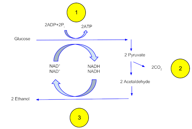
Fermentation occurs at around 30 degrees C over two to three days, while the yeast gorge themselves on the glucose-rich slurry. The glucose is transported into the yeast, where each glucose molecule is enzymatically split into two three-carbon pyruvate molecules. The pyruvates are then broken down into two molecules of acetaldehyde and two of CO2. The two acetaldehyde molecules then undergo a reduction reaction that creates two ethanol molecules. The yeast benefits from all this work by converting two molecules of ADP into two molecules of ATP, which captures the chemical energy in the glucose molecule into a form that can be used to power its metabolic processes, including making more yeast to take advantage of the bounty of glucose.
Anaerobic fermentation of one mole of glucose yields two moles of ethanol and two moles of CO2.
After the population of yeast grows to the point where they use up all the glucose, the mix in the reactors, which contains about 12-15% ethanol and is referred to as beer, is pumped into a series of three distillation towers. The beer is carefully heated to the boiling point of ethanol, 78 °C. The ethanol vapors rise through the tower to a condenser, where they change back into the liquid phase and trickle down into collecting trays lining the tower. The liquid distillate is piped to the next two towers, where the same process occurs and the distillate becomes increasingly purer. At the end of the final distillation, the mixture is about 95% pure ethanol, or 190 proof. That’s the limit of purity for fractional distillation, thanks to the tendency of water and ethanol to form an azeotrope, a mixture of two or more liquids that boils at a constant temperature. To drive off the rest of the water, the distillate is pumped into large tanks containing zeolite, a molecular sieve. The zeolite beads have pores large enough to admit water molecules, but too small to admit ethanol. The water partitions into the zeolite, leaving 99% to 100% pure (198 to 200 proof) ethanol behind. The ethanol is mixed with a denaturant, usually 5% gasoline, to make it undrinkable, and pumped into storage tanks to await shipping.
Nothing Goes to Waste
The muck at the bottom of the distillation towers, referred to as whole stillage, still has a lot of valuable material and does not go to waste. The liquid is first pumped into centrifuges to separate the remaining grain solids from the liquid. The solids, called wet distiller’s grain or WDG, go to a rotary dryer, where hot air drives off most of the remaining moisture. The final product is dried distiller’s grain with solubles, or DDGS, a high-protein product used to enrich animal feed. The liquid phase from the centrifuge is called thin stillage, which contains the valuable corn oil from the germ. That’s recovered and sold as an animal feed additive, too.
Ethanol fermentation produces mountains of DDGS, or dried distiller’s grain solubles. This valuable byproduct can account for 20% of an ethanol plant’s income. Source: Inside an Ethanol Plant (YouTube).
The final valuable product that’s recovered is the carbon dioxide. Fermentation produces a lot of CO2, about 17 pounds per bushel of feedstock. The gas is tapped off the tops of the fermentation vessels by CO2 scrubbers and run through a series of compressors and coolers, which turn it into liquid carbon dioxide. This is sold off by the tanker-full to chemical companies, food and beverage manufacturers, who use it to carbonate soft drinks, and municipal water treatment plants, where it’s used to balance the pH of wastewater.
There are currently 187 fuel ethanol plants in the United States, most of which are located in the Midwest’s corn belt, for obvious reasons. Together, these plants produced more than 16 billion gallons of ethanol in 2024. Since each bushel of corn yields about 3 gallons of ethanol, that translates to an astonishing 5 billion bushels of corn used for fuel production, or about a third of the total US corn production.
Shade is the mortal enemy of solar panels; even a little shade can cause a disproportionate drop in power output. [Alex Beale] reviewed a “revolutionary” shade-tolerant panel by Renology in a video embedded below. The results are fascinating.
While shading large portions of the panels using cardboard to cut off rows of cells, or columns of cells, the shade tolerant panel does very well compared to the standard panel– but when natural, uneven shading is applied to the panel, very little difference is seen between the standard and active panels in [Alex]’s test. We suspect there must be some active components to keep power flowing around shaded cells in the Renology panel, allowing it to perform well in the cardboard tests. When the whole panel is partially shaded, there’s no routing around it, and it performs normally.
It’s hard to see a real-world case that would justify the extra cost, since most shading doesn’t come with perfect straight-line cutoffs. Especially considering the added cost for this “shade tolerant” technology (roughly double normal panels).
The hack we have for you today is among our most favorite types of hack: a good, honest, simple, and well documented implementation that meets a real need. Our hacker [Solo Pilot] has sent in a link to their basement monitor.
The documentation is quite good. It’s terse but comprehensive with links to related information. It covers the background, requirements, hardware design, sensors, email and SMS alerts, software details, and even has some credits at the end.
Implementing this project would be a good activity for someone who has already made an LED flash and wants to take their skills to the next level by sourcing and assembling the hardware and then configuring, compiling, deploying, and testing the software for this real-world project.
To make this project work you will need to know your way around the Arduino IDE in order to build the software from the src.zip file included with the documentation (hint: extract the files from src.zip into a directory called AHT20_BMP280 before opening AHT20_BMP280.ino and make sure you add necessary boards and libraries).
One feature of the basement monitor that we would like to see is a periodic “everything’s okay” signal from the device, just so we can confirm that the reason we’re not getting an alarm about flooding in the basement is because there is no flood, and not because the battery ran dead or the WiFi went offline.
If you’ve recently started on your journey into where electronics meets software a project such as this one is a really great place to go next. And of course once you are proficient with the ESP8266 there are a thousand such projects here at Hackaday that you can cut your teeth on. Such as this clock and this fault injection device.
The Bipolar Junction Transistor (BJT, such as NPN and PNP) was invented by Bell Labs in 1947. Later came Transistor-Transistor Logic (TTL) made with BJTs. The problem with TTL was too much power consumption.
Enter the energy-efficient Field-Effect Transistor (FET). The FET is better suited to processing information as it is voltage-controlled, unlike the BJT which is current-controlled. Advantages of FETs include high input impedance, low power consumption, fast switching speed, being well suited to Very-Large-Scale Integration (VLSI), etc.
The cornerstone of Complementary Metal-Oxide-Semiconductor (CMOS) technology which came to replace TTL was a type of FET known as the Metal-Oxide-Semiconductor Field-Effect Transistor (MOSFET). The type of MOSFET most commonly used in CMOS integrated circuits is the Enhancement-mode MOSFET which is normally off and needs gate voltage to conduct.
A transistor’s technology generation is given with the “process node”, in nanometers (nm). This used to mean the size of the smallest feature that could be fabricated, but these days it’s just a marketing term (smaller is “better”). Planar CMOS MOSFETs were initially dominant (through ~28nm), then came SOI MOSFETs (28nm to 16nm), then FinFETs (16nm to 5nm), and now finally Gate-All-Around FETs (GAAFETs, 3nm and beyond).
All of that in order to say that this new transistor from [Hailin Peng] and his team is a GAAFET. It’s made from bismuth oxyselenide (Bi₂O₂Se) for the channel, and bismuth selenite oxide (Bi₂SeO₅) as the gate material. See the article for further details.
Keep in mind that at this point in time we only have a prototype from a lab and the gory details about how to mass-produce these things, assuming that’s even possible, haven’t yet been worked out. We have previously discussed the difficulty of manufacturing state-of-the-art transistors. If you’re interested in bismuth be sure to check out how to use bismuth for desoldering.
It’s fair to say that QR codes are a technology that has finally come of age. A decade or more ago they were a little over-hyped and sometimes used in inappropriate or pointless ways, but now they are an accepted and useful part of life.
They’re not without their faults though, one of which is that despite four increasingly redundant levels of error correction, there comes a point at which a degraded QR code can no longer be read. [HumanQR] is soliciting these broken QR codes for research purposes and inclusion in an eventual open-source database, and they’ll even have a shot at repairing your submissions for you.
It’s a problem inherent to all digital media, that once the limit of whatever error correction they contain has been reached, they arrive at a cliff-edge at which they go immediately from readability to non readability. The example given in the linked article is a locator tag on a stray cat, it had been rubbed away in part. Improving its contrast, sharply defining its edges, and improving the definition of its fiducials was able to revive it, we hope leading to the cat being returned home.
The idea is that by studying enough damaged codes it should be possible to identify the means by which they become degraded, and perhaps come up with a way to inform some repair software. Meanwhile if you are interested, you might want to learn more about how they work, the hard way.
Morse code can be daunting to learn when you’re new to the game, particularly if you need it to pass your desired radio license. However, these days, there are a great many tools to aid in the learning process. A good example is the Morse Master from [Arnov Sharma].
The Morse Master is a translator for Morse code, which works in two ways. You can access it via a web app, and type in regular letters which it then flashes out as code on its in-built LEDs. Alternatively, you can enter Morse manually using the physical key, and the results will be displayed on the web app. The Morse key itself is built into the enclosure using 3D printed components paired with a Cherry-style keyboard switch. It’s perhaps not the ideal solution for fast keying, with its limited rebound, but it’s a quick and easy way to make a functional key for practice purposes. If you want to go faster, though, you might want to upgrade to something more capable. We’d also love to see a buzzer added, since Morse is very much intended as an auditory method of communication.
Strenghtening FDM prints has been discussed in detail over the last years. Solutions and results vary as each one’s desires differ. Now [TenTech] shares his latest improvements on his post-processing script that he first created around January. This script literally bends your G-code to its will – using non-planar, interlocking sine wave deformations in both infill and walls. It’s now open-source, and plugs right into your slicer of choice: PrusaSlicer, OrcaSlicer, or Bambu Studio. If you’re into pushing your print strength past the limits of layer adhesion, but his former solution wasn’t quite the fit for your printer, try this improvement.
Traditional Fused Deposition Modeling (FDM) prints break along layer lines. What makes this script exciting is that it lets you introduce alternating sine wave paths between wall loops, removing clean break points and encouraging interlayer grip. Think of it as organic layer interlocking – without switching to resin or fiber reinforcement. You can tweak amplitude, frequency, and direction per feature. In fact, the deformation even fades between solid layers, allowing smoother transitions. Structural tinkering at its finest, not just a cosmetic gimmick.
This thing comes without needing a custom slicer. No firmware mods. Just Python, a little G-code, and a lot of curious minds. [TenTech] is still looking for real-world strength tests, so if you’ve got a test rig and some engineering curiosity, this is your call to arms.
It’s amazing how quickly medical science made radiography one of its main diagnostic tools. Medicine had barely emerged from its Dark Age of bloodletting and the four humours when X-rays were discovered, and the realization that the internal structure of our bodies could cast shadows of this mysterious “X-Light” opened up diagnostic possibilities that went far beyond the educated guesswork and exploratory surgery doctors had relied on for centuries.
The problem is, X-rays are one of those things that you can’t see, feel, or smell, at least mostly; X-rays cause visible artifacts in some people’s eyes, and the pencil-thin beam of a CT scanner can create a distinct smell of ozone when it passes through the nasal cavity — ask me how I know. But to be diagnostically useful, the varying intensities created by X-rays passing through living tissue need to be translated into an image. We’ve already looked at how X-rays are produced, so now it’s time to take a look at how X-rays are detected and turned into medical miracles.
Taking Pictures
For over a century, photographic film was the dominant way to detect medical X-rays. In fact, years before Wilhelm Conrad Röntgen’s first systematic study of X-rays in 1895, fogged photographic plates during experiments with a Crooke’s tube were among the first indications of their existence. But it wasn’t until Röntgen convinced his wife to hold her hand between one of his tubes and a photographic plate to create the first intentional medical X-ray that the full potential of radiography could be realized.
“Hand mit Ringen” by W. Röntgen, December 1895. Public domain.
The chemical mechanism that makes photographic film sensitive to X-rays is essentially the same as the process that makes light photography possible. X-ray film is made by depositing a thin layer of photographic emulsion on a transparent substrate, originally celluloid but later polyester. The emulsion is a mixture of high-grade gelatin, a natural polymer derived from animal connective tissue, and silver halide crystals. Incident X-ray photons ionize the halogens, creating an excess of electrons within the crystals to reduce the silver halide to atomic silver. This creates a latent image on the film that is developed by chemically converting sensitized silver halide crystals to metallic silver grains and removing all the unsensitized crystals.
Other than in the earliest days of medical radiography, direct X-ray imaging onto photographic emulsions was rare. While photographic emulsions can be exposed by X-rays, it takes a lot of energy to get a good image with proper contrast, especially on soft tissues. This became a problem as more was learned about the dangers of exposure to ionizing radiation, leading to the development of screen-film radiography.
In screen-film radiography, X-rays passing through the patient’s tissues are converted to light by one or more intensifying screens. These screens are made from plastic sheets coated with a phosphorescent material that glows when exposed to X-rays. Calcium tungstate was common back in the day, but rare earth phosphors like gadolinium oxysulfate became more popular over time. Intensifying screens were attached to the front and back covers of light-proof cassettes, with double-emulsion film sandwiched between them; when exposed to X-rays, the screens would glow briefly and expose the film.
By turning one incident X-ray photon into thousands or millions of visible light photons, intensifying screens greatly reduce the dose of radiation needed to create diagnostically useful images. That’s not without its costs, though, as the phosphors tend to spread out each X-ray photon across a physically larger area. This results in a loss of resolution in the image, which in most cases is an acceptable trade-off. When more resolution is needed, single-screen cassettes can be used with one-sided emulsion films, at the cost of increasing the X-ray dose.
Wiggle Those Toes
Intensifying screens aren’t the only place where phosphors are used to detect X-rays. Early on in the history of radiography, doctors realized that while static images were useful, continuous images of body structures in action would be a fantastic diagnostic tool. Originally, fluoroscopy was performed directly, with the radiologist viewing images created by X-rays passing through the patient onto a phosphor-covered glass screen. This required an X-ray tube engineered to operate with a higher duty cycle than radiographic tubes and had the dual disadvantages of much higher doses for the patient and the need for the doctor to be directly in the line of fire of the X-rays. Cataracts were enough of an occupational hazard for radiologists that safety glasses using leaded glass lenses were a common accessory.
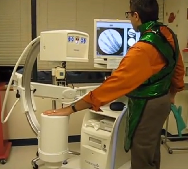
How not to test your portable fluoroscope. The X-ray tube is located in the upper housing, while the image intensifier and camera are below. The machine is generally referred to as a “C-arm” and is used in the surgery suite and for bedside pacemaker placements. Source: Nightryder84, CC BY-SA 3.0.
One ill-advised spin-off of medical fluoroscopy was the shoe-fitting fluoroscopes that started popping up in shoe stores in the 1920s. Customers would stick their feet inside the machine and peer at a fluorescent screen to see how well their new shoes fit. It was probably not terribly dangerous for the once-a-year shoe shopper, but pity the shoe salesman who had to peer directly into a poorly regulated X-ray beam eight hours a day to show every Little Johnny’s mother how well his new Buster Browns fit.
As technology improved, image intensifiers replaced direct screens in fluoroscopy suites. Image intensifiers were vacuum tubes with a large input window coated with a fluorescent material such as zinc-cadmium sulfide or sodium-cesium iodide. The phosphors convert X-rays passing through the patient to visible light photons, which are immediately converted to photoelectrons by a photocathode made of cesium and antimony. The electrons are focused by coils and accelerated across the image intensifier tube by a high-voltage field on a cylindrical anode. The electrons pass through the anode and strike a phosphor-covered output screen, which is much smaller in diameter than the input screen. Incident X-ray photons are greatly amplified by the image intensifier, making a brighter image with a lower dose of radiation.
Originally, the radiologist viewed the output screen using a microscope, which at least put a little more hardware between his or her eyeball and the X-ray source. Later, mirrors and lenses were added to project the image onto a screen, moving the doctor’s head out of the direct line of fire. Later still, analog TV cameras were added to the optical path so the images could be displayed on high-resolution CRT monitors in the fluoroscopy suite. Eventually, digital cameras and advanced digital signal processing were introduced, greatly streamlining the workflow for the radiologist and technologists alike.
Get To The Point
So far, all the detection methods we’ve discussed fall under the general category of planar detectors, in that they capture an entire 2D shadow of the X-ray beam after having passed through the patient. While that’s certainly useful, there are cases where the dose from a single, well-defined volume of tissue is needed. This is where point detectors come into play.
In medical X-ray equipment, point detectors often rely on some of the same gas-discharge technology that DIYers use to build radiation detectors at home. Geiger tubes and ionization chambers measure the current created when X-rays ionize a low-pressure gas inside an electric field. Geiger tubes generally use a much higher voltage than ionization chambers, and tend to be used more for radiological safety, especially in nuclear medicine applications, where radioisotopes are used to diagnose and treat diseases. Ionization chambers, on the other hand, were often used as a sort of autoexposure control for conventional radiography. Tubes were placed behind the film cassette holders in the exam tables of X-ray suites and wired into the control panels of the X-ray generators. When enough radiation had passed through the patient, the film, and the cassette into the ion chamber to yield a correct exposure, the generator would shut off the X-ray beam.
Another kind of point detector for X-rays and other kinds of radiation is the scintillation counter. These use a crystal, often cesium iodide or sodium iodide doped with thallium, that releases a few visible light photons when it absorbs ionizing radiation. The faint pulse of light is greatly amplified by one or more photomultiplier tubes, creating a pulse of current proportional to the amount of radiation. Nuclear medicine studies use a device called a gamma camera, which has a hexagonal array of PM tubes positioned behind a single large crystal. A patient is injected with a radioisotope such as the gamma-emitting technetium-99, which accumulates mainly in the bones. Gamma rays emitted are collected by the gamma camera, which derives positional information from the differing times of arrival and relative intensity of the light pulse at the PM tubes, slowly building a ghostly skeletal map of the patient by measuring where the 99Tc accumulated.
Going Digital
Despite dominating the industry for so long, the days of traditional film-based radiography were clearly numbered once solid-state image sensors began appearing in the 1980s. While it was reliable and gave excellent results, film development required a lot of infrastructure and expense, and resulted in bulky films that required a lot of space to store. The savings from doing away with all the trappings of film-based radiography, including the darkrooms, automatic film processors, chemicals, silver recycling, and often hundreds of expensive film cassettes, is largely what drove the move to digital radiography.
After briefly flirting with phosphor plate radiography, where a sensitized phosphor-coated plate was exposed to X-rays and then “developed” by a special scanner before being recharged for the next use, radiology departments embraced solid-state sensors and fully digital image capture and storage. Solid-state sensors come in two flavors: indirect and direct. Indirect sensor systems use a large matrix of photodiodes on amorphous silicon to measure the light given off by a scintillation layer directly above it. It’s basically the same thing as a film cassette with intensifying screens, but without the film.
Direct sensors, on the other hand, don’t rely on converting the X-ray into light. Rather, a large flat selenium photoconductor is used; X-rays absorbed by the selenium cause electron-hole pairs to form, which migrate to a matrix of fine electrodes on the underside of the sensor. The current across each pixel is proportional to the amount measured to the amount of radiation received, and can be read pixel-by-pixel to build up a digital image.
Entry-level oscilloscopes are a great way to get some low-cost instrumentation on a test bench, whether it’s for a garage lab or a schoolroom. But the cheapest ones are often cheap for a reason, and even though they work well for the price they won’t stand up to more advanced equipment. But missing features don’t have to stay missing forever, as it’s possible to augment them to get some of these features. [Tommy’s] project shows you one way to make a silk purse from a sow’s ear, at least as it relates to oscilloscopes.
Most of the problem with these lower-cost tools is their low precision due to fewer bits of analog-digital conversion. They also tend to be quite noisy, further lowering the quality of the oscilloscope. [Tommy] is focusing his efforts on the DSO138-mini, an oscilloscope with a bandwidth of 100 kHz and an effective resolution of 10 bits. The first step is to add an anti-aliasing filter to the input, which is essentially a low-pass filter that removes high frequency components of the signal, which could cause a problem due to the lower resolution of the device. After that, digital post-processing is done on the output, which removes noise caused by the system’s power supply, among other things, and essentially acts as a second low-pass filter.
In part 2 of the project, [Tommy] demonstrates the effectiveness of these two methods with experimental data, showing that a good percentage of the noise on a test signal has been removed from the output. All the more impressive here is that the only additional cost besides the inexpensive oscilloscope itself is for a ceramic capacitor that costs around a dollar. We were also impressed: [Tommy] is a junior in high school!
We’ve all had times where we knew we had some part but we had to go searching for it all over as it wasn’t where we thought we put it. Organizing the numerous components, parts, and supplies that go into your projects can be a daunting task, especially if you use the same type of part at different times for different projects. It helps to have a framework to keep track of all the small details. Binner is an open source project that aims to allow you to easily maintain a database that can be customized to your use.
In a recent video for DigiKey, [Byte Sized Engineer] used Binner to track the locations of his components and parts in his freshly organized workshop. Binner already has the ability to read the labels used by well-known electronics suppliers via a barcode scanner, and uses that information to populate your inventory. It even grabs quantities and links in a datasheet for your newly added part. The barcode scanner can also be used to retrieve the contents of a location, so with a single scan Binner can bring up everything residing at that location.
Binner can be run locally so there isn’t the concern of putting in all the effort to build up your database just to have an internet outage make it inaccessible. Another cool feature is that it allows you to print labels, you can customize the fields to display the values you care about.
Hazelight Studios anunció en X que Split Fiction, su próxima aventura cooperativa que salta entre mundos de ciencia ficción y fantasía, será nativo de Steam y está verificado para Steam Deck. Desde el 6 de marzo, los usuarios de estas plataformas podrán emprender la aventura de Mio y Zoe con cualquier persona de su lista de amigos. Esto estará reforzado con el Pase de Amigo, que le permite a un segundo jugador disfrutar del juego completo gratis junto con un compañero que tenga Split Fiction sin importar dónde se encuentre ni su plataforma.
Además, a continuación encontrarás un resumen de las especificaciones de PC y características adicionales compartidas en el post más reciente del blog:
Resolución dinámica en 4K y 60 cuadros por segundo en Xbox Series X y PS5, 1080p/60fps en Xbox Series S
Soporte para monitores ultrawide 21:9 y 32:9 en PC
Requerimientos de PC y recomendaciones
La precarga ya se encuentra disponible en todas las plataformas
Funciones de accesibilidad como teclas programables, saltar al próximo checkpoint, y reducir el daño.
FSR 3.1 de AMD (no tiene XeSS de Intel ni DLSS de Nvidia, aunque tampoco lo necesita realmente. El DLAA no hubiese estado de más DLAA de todos modos).
Requisitos Mínimos:
Requiere un procesador y un sistema operativo de 64 bits
SO: 64 bit Windows 10/11
Procesador: Intel Core i5-6600K o AMD Ryzen 5 2600X
Previamente, EA y Hazelight Studios publicaron un trailer de Split Fiction que destaca el regreso de una característica clásica de Hazelight, el Pase de Amigo, que le permite a los jugadores compartir la explosiva experiencia cooperativa con un amigo de forma gratuita con sólo una copia del juego.
En Split Fiction, el Pase de Amigo está de regreso y mejor que nunca con una nueva función de crossplay, que le permite a todos formar equipo en diferentes plataformas incluyendo PC, PlayStation 5 y Xbox Series X|S.
Si ninguno de los jugadores tiene una copia del juego, ambos compañeros podrán igualmente jugar a la prueba GRATUITA del juego con el Pase de Amigo para probar la magia cooperativa de Hazelight. Conoce más acerca del Pase de Amigo y cómo usar la función aquí.
Dando más información acerca de las dos protagonistas del juego, Mio y Zoe, el previo nuevo tráiler revela más detalles acerca de las historias de los personajes y el viaje que los jugadores experimentarán a través de los diversos mundos de Split Fiction.
El tráiler también destaca la historia cautivadora del juego, con la autora de ciencia ficción Mio y la escritora de fantasía Zoe dejando de lado sus diferencias, descubriendo secretos escondidos sobre ellas mismas y trabajando juntas para superar las dificultades contra todo pronóstico.
Desarrollado por Hazelight Studios, las mentes creativas detrás de It Takes Two, ganador de Juego del Año 2021 con más de 20 millones de unidades vendidas mundialmente, llega un juego cooperativo de acción y aventuras de pantalla dividida donde los jugadores saltarán entre mundos de ciencia ficción y fantasía.
Split Fiction cuenta la historia de Mio y Zoe, dos escritoras opuestas que unen sus fuerzas para escapar de una simulación de mundos creados con base en sus propias historias. En esta narrativa de amistad inesperada, las y los jugadores pueden disfrutar de aventuras en pantalla dividida, y construir sus habilidades cooperativas mientras cruzan las fronteras entre diferentes mundos.
Una característica clásica de Hazelight Studios, el Pase de Amigo, el cual le permite a un jugador que tiene el juego invitar a un amigo a jugar gratuitamente, está de regreso y expandido con opciones de crossplay habilitadas para PlayStation, Xbox y PC a través de Steam. Split Fiction se lanzará el 6 de marzo de 2025 en PlayStation 5, Xbox Series X|S y PC a través de Steam, Epic Games Store y la EA app por $49.99 dólares.
«En Hazelight, hemos estado creando juegos cooperativos por 10 años, y con cada juego vamos más allá de lo que los jugadores esperan de los juegos cooperativos de acción y aventuras. Estoy tan orgulloso de lo que hemos construido con Split Fiction. Déjenme decirles, les va a volar la cabeza», dijo Josef Fares, fundador de Hazelight Studios. «Debido a que Mio y Zoe alternan entre mundos de ciencia ficción y fantasía, hemos podido hacer algunas cosas muy locas con la jugabilidad y narrativa. Esta es definitivamente nuestra aventura cooperativa más épica hasta la fecha».
En Split Fiction, los jugadores descubrirán variedad de mecánicas y habilidades de ciencia ficción y fantasía. Escapa de un sol que se está convirtiendo en supernova, desafía a un mono a una batalla de baile, intenta realizar algunos trucos geniales en aeropatín, pelea contra un gatito malvado y date una vuelta en todo tipo de cosas, desde motos gravitatorias hasta un tiburón de arena. Con mundos que son completamente diferentes entre sí, sorprendentes desafíos esperan a los jugadores en cada turno.
Mio y Zoe son escritoras contrastantes, una de ciencia ficción y otra de fantasía, que terminan atrapadas en sus propias historias luego de ser conectadas a una máquina diseñada para robar sus ideas creativas. Alternando entre mundos, tendrán que trabajar juntas y dominar distintas habilidades para conseguir salir con sus recuerdos intactos.
«Las amistades y grandes recuerdos se forman jugando increíbles juegos cooperativos juntos, y nadie lo hace mejor que Hazelight», dijo Jeff Gamon, Manager General de EA Partners. «Estamos emocionados de continuar nuestra alianza de largo plazo con Josef y su talentoso equipo para traer a la vida otra innovadora aventura colaborativa; una que sigue empujando los límites y redefine lo que los jugadores pueden experimentar juntos dentro y fuera de la pantalla».
Acerca de Split Fiction
Disfruta de una aventura alucinante que traspasa los límites de lo conocido mientras te adentras en los diversos mundos de Split Fiction, una aventura cooperativa del estudio desarrollador de It Takes Two (título ganador del Juego del año 2021).
Mio y Zoe son escritoras opuestas que se dedican a hacer historias de ciencia ficción y fantasía. Ambas quedan atrapadas en sus propias historias después de que las conectaran a una máquina diseñada para robar sus ideas creativas.
Tendrán que confiar mutuamente para liberarse con sus recuerdos intactos, trabajando en equipo para dominar una variedad de habilidades y superar diversos desafíos mientras saltan entre mundos de ciencia ficción y fantasía en esta inesperada historia de amistad.
Split Fiction es una experiencia única de acción y aventura que te mantendrá al borde del sillón con momentos inesperados. En un minuto estarás domando adorables dragones y al siguiente lucharás como ninjas cibernéticos, tratarás de escapar de trolls aterradores o tendrás que esquivar autos voladores lanzados por un asistente de estacionamiento robótico. Es extraño, es salvaje y está diseñado para compartirse.
Requisitos Mínimos:
Requiere un procesador y un sistema operativo de 64 bits
SO: 64 bit Windows 10/11
Procesador: Intel Core i5-6600K o AMD Ryzen 5 2600X
Hazelight, estudio creador del Juego del año de 2021 (It Takes Two), es un galardonado estudio de desarrollo de videojuegos independiente de Estocolmo (Suecia) fundado en 2014 por Josef Fares, director de cine y creador del aclamado juego Brothers: A Tale of Two Sons.
Hazelight tiene el compromiso de llevar al límite la creatividad en los juegos. En 2018, Hazelight lanzó A Way Out, el primer juego de aventuras y acción en tercera persona exclusivamente cooperativo, como parte del programa EA Originals.
Acerca de EA Originals
EA Originals celebra a aquellos que se animan a explorar. Estos estudios forjan nuevas formas de jugar al reunir a desarrolladores con visiones audaces. Aquí, estos desarrolladores usan su libertad artística para llegar a jugadores que atesorarán las nuevas experiencias que han creado.
Si bien Sony Interactive Entertainment y UltiZero Games publicaron los requisitos de PC de Lost Soul Aside para resolución 1080p a través de Steam y Epic Games Store hace pocos días, el publisher ha actualizada la página del juego en su propio portal y ha dado a conocer cuáles serán los requisitos para resoluciones adicionales, como también las especificaciones para jugar con ray tracing activado (el cual será exclusivo de PC y no estará disponible en PlayStation).
A pesar de que los diferentes requisitos no especifican resoluciones ni el uso de tecnología de reescalado y Frame Generation, pero spi presets gráficos, podemos inferir que los dos primeros (los publicados previamente) son para jugar en 1080p a 30 FPS (GTX 1060) con detalles en detalles Bajos y el otro (RTX 2060) para jugar en 1080p a 60 FPS con detalles en Medio. El tercero, también para 1080p, sería para jugar a 60 FPS pero con detalles en Alto.
Por último, tenemos la configuración en Alto junto con trazado de rayos activado (seguramente en resolución 1440p) y para esto se requerirá una RTX 4080 SUPER o una RX 7900 XT, mientras que para detalles Ultra con ray tracing en 4K a 60 FPS, extrañamente, se recomienda una RTX 5070 Ti que rinde prácticamente igual que una RTX 4080, con el diferencial del Multi-Frame Generation, el cual estará presente junto con las demás tecnologías actualizadas de DLSS 4 ( súper resolución y ray reconstruction).
Una vez más, no se menciona el uso de DLSS de Nvidia, XeSS de Intel o FSR de AMD, ya sea con o sin Generación de Fotogramas, pero está claro que el cuadro está dividido en la parte superior para 1080p, mientras que las dos configuraciones inferiores son para 1440p y 4K, respectivamente
Las reservas de Lost Soul Aside, el RPG de acción y aventura con combate al estilo Devil May Cry, ya están disponibles para PC(vía Steamy Epic Games Store) y PlayStation 5 por US$ 59.99 para la Edición Estándar y US$ 69.99 para la Edición Digital Deluxe y el juego se lanzará el próximo 30 de mayo.
Características de PC de Lost Soul Aside:
Gráficos optimizados en 4K – Explora paisajes majestuosos y llenos de vida, con opciones gráficas ajustables y una velocidad de fotogramas ilimitada, con soporte para tecnologías que mejoran el rendimiento.
Trazado de rayos – Descubre un realismo visual inigualable con sombras detalladas, reflejos precisos y efectos luminosos de alta fidelidad, gracias a la avanzada tecnología de trazado de rayos.
Compatibilidad con el mando DualSense – Siente cada golpe y la intensidad de la batalla en tus manos con los gatillos adaptativos y la respuesta háptica del mando DualSense de PlayStation con una conexión por USB.
Alto rango dinámico – Disfruta de colores más vivos, unos niveles de brillo impresionantes y un contraste marcado por una experiencia visual ultrarrealista y detallada en monitores de juego compatibles con HDR.
Bonificaciones por reserva
El atuendo original de Kaser de la primera presentación del juego, lo que les dará a los jugadores una mirada nostálgica de cómo comenzó todo.
Un paquete de inicio de moneda en el juego para ayudarte a dar inicio a tu aventura.
Un paquete de pociones de sanación, perfecto para aquellas desafiantes primeras batallas en el juego.
Adquiere la edición estándar de Lost Soul Aside. También habrá una edición digital Deluxe
La edición digital Deluxe de Lost Soul Aside incluirá el juego, todos los incentivos de reserva y también el atuendo dorado exclusivo de Arena, tres diseños de fragmentos de arma únicos, dos accesorios del juego que proporcionan potenciaciones útiles para tu viaje y la banda sonora y el libro de arte digitales. No te pierdas estos elementos adicionales, son una muestra de profundo agradecimiento para todos los que nos apoyaron desde el inicio.
Lost Soul Aside
Tres aspectos para armas: Trueno del génesis, Ascua eterna y Cristal del abismo
Aspecto para Arena: Fulgor dorado
Collar de rubí (potenciador de vitalidad)
Medalla engarzada (potenciador de EXP)
Banda sonora digital
Libro de ilustraciones digital
«Yang Bing – Game Director & CEO, Ultizero Games
La espera terminó. Soy Yang Bing, como creador de Lost Soul Aside, no podría estar más emocionado de compartir algunas grandiosas noticias: ¡nuestro RPG de acción se lanzará oficialmente en PlayStation 5 y PC el 30 de mayo de 2025! Lo que comenzó como el sueño de una persona (yo, una computadora y noches en vela interminables) evolucionó para convertirse en una gran aventura repleta de gráficos asombrosos y combate lleno de adrenalina.
Permíteme llevarte al detrás de escena para que seas testigo de todo el cariño, el entusiasmo y el trabajo duro que se le dedicó a este juego. Ya sea que estés aquí por el combate con estilo o la historia atrapante, hay mucho en lo que ahondar.
Un mundo que vive y respira
Crear el mundo de Lost Soul Aside fue como pintar con imaginación en un lienzo de fantasía y ciencia ficción. Viajarás por paisajes llenos de vida: llanuras iluminadas por el sol, ruinas antiguas misteriosas y dimensiones alternativas que rebozan de energía. Este mundo no solo es atractivo visualmente, también está lleno de secretos, monstruos y eventos impredecibles que no dejarán de captar tu atención.
Pero hablemos de lo que realmente define la experiencia: el combate.
Combate de gran intensidad
Mi objetivo era simple: lograr un combate fluido, rápido y con estilo que resultara atrapante al punto de no querer soltar el control. El arma que cambia de forma de Kaser se adapta a tu estilo de combate. ¿Eres un espadachín preciso? ¿Prefieres los ataques devastadores a distancia? ¿O prefieres poder moverte a alta velocidad? Sin importar cuál sea tu preferencia, los diferentes tipos de armas te resultarán útiles.
Un momento significativo durante el desarrollo fue el diseño de las batallas de jefes. La lucha con enormes dragones sigue siendo una de mis favoritas. Te obliga tener que alternar entre movimientos de evasión en el aire, calcular el tiempo perfecto para contrarrestar ataques y atacar de forma implacable. Eso sin mencionar que es un deleite a nivel visual que te hace sentir parte de tu propia película de acción épica.
Detrás de los movimientos llamativos, hay profundidad para los jugadores que adoran experimentar. Puedes personalizar el equipamiento, conectar combos sinérgicos y armar una estrategia con Arena, el compañero en forma de dragón de Kaser. Sus habilidades no son solo de apoyo, sino que son un factor determinante, ya que pueden cambiar el curso de la batalla a tu favor si se usan sabiamente.
Desde enfrentamientos casuales con enemigos hasta grandes batallas preestablecidas, el combate en Lost Soul Aside está diseñado para mantenerte al borde de tu asiento, y lleva tus habilidades al límite al mismo tiempo que recompensa tu creatividad y precisión.
Una historia especial para mí
Si bien el combate es lo más destacado, Lost Soul Aside también entreteje una narrativa sobre el viaje de redención y descubrimiento de Kaser. A medida que descubre la verdad sobre Arena y su poder compartido, los jugadores se enfrentarán a diversos desafíos personales y conflictos de alto riesgo. La historia se centra en crear momentos y conexiones memorables, lo que ofrece sorpresas sin abrumar la experiencia de juego. Y sí, hay mucho drama, porque no hay nadie que no adore un momento digno de asombro, ¿verdad?
Modo para PlayStation
Lost Soul Aside fue diseñado con la consola PlayStation en mente, y estoy emocionado con las mejoras que hemos implementado.
Tiempos de carga increíblemente rápidos: Con la SSD de PS5, te desplazarás con fluidez entre la exploración y el combate.
Magia de control DualSense: Siente la tensión de cada movimiento de la espada con gatillos adaptativos y respuesta háptica.
Gráficos 4K: El mundo cobra vida con increíble nivel de detalle con iluminación dinámica y entornos cuidadosamente diseñados.
Jugadores de PC, no se preocupen: el juego está completamente optimizado para proporcionar un rendimiento fluido sin perder ninguna de las funciones de juego principales.
Este viaje ha sido increíble y estoy muy emocionado por entrar en el mundo de Kaser y Arena. Gracias por el apoyo a lo largo de los altibajos del proceso de desarrollo. Ya casi es hora de ver de qué se trata Lost Soul Aside. ¡Hasta entonces, disfruta el juego!»
Acerca de Lost Soul Aside
Embárcate en una odisea épica para rescatar a tu hermana y a toda la humanidad ante la amenaza de invasores dimensionales en Lost Soul Aside, un elegante juego de rol (RPG) de acción y aventura para un jugador.
Mezcla combos ultrarrápidos, aprende nuevas habilidades y mejora tus armas a medida que te enfrentes a formidables enemigos y jefes colosales en combates dinámicos y rápidos.
«La guerra terminó hace diez años y aparecieron los monstruos desconocidos. Kazer se fusionó accidentalmente con una antigua raza llamada Arena. Luego se embarcaron en un viaje para buscar los misteriosos cristales con sus propios fines. Esto no es para salvar el mundo, solo para salvarme a mí mismo.»
Características principales:
UN MUNDO ENFRENTADO
Aquella noche lo iba a cambiar todo. El momento en el que Kaser, Louisa y la resistencia saldrían por fin de las sombras: una oportunidad para sabotear las fastuosas celebraciones del emperador, combatir su yugo opresor y darle al pueblo una razón para luchar.
Algo a lo que aferrarse. Pero, en un abrir y cerrar de ojos, todo se desmoronó. Una violenta lluvia de meteoritos cayó del cielo, destruyéndolo todo a su paso. Se llevaron el alma de Louisa. Kaser cambió.
Con un nuevo aliado a su lado, Kaser parte en una misión para rescatar a su hermana del más allá, en la que descubrirá el verdadero origen de la lluvia de meteoritos.La llegada de los nihilos, seres invasores de otra dimensión, trajo consigo un férreo deseo de conquista, de destruir a las demás especies y de robar la energía de sus almas.
Con sus nuevas habilidades, Kaser tendrá que atravesar mundos y dimensiones para enfrentarse a enemigos temibles, y poder salvar a su hermana y a toda la humanidad. Da comienzo el viaje de nuestro héroe…
LUCHA POR TODO
Las leyendas se forjan en la adversidad. Así que prepárate para un combate enérgico y cargado de acción, que pondrá a prueba tus reflejos y tu resistencia.El enemigo es implacable y no tendrá piedad. Tú tampoco debes tenerla.
Despliega tus habilidades de combate y esgrima para encadenar combos dinámicos y fluidos, y provoca un daño devastador en cada fase del combate. Piensa rápido para esquivar o desviar los ataques, vencer a criaturas peligrosas e imponentes jefes monstruosos, y sobrevive a encuentros trepidantes.
Fácil de entender, pero difícil de dominar. Lucha a tu manera: cambia de arma, combina patrones de ataque diferentes y observa los movimientos del enemigo en combates llenos de adrenalina, acompañados de unos efectos visuales impresionantes.
EVOLUCIÓN DEL PERSONAJE
En Lost Soul Aisde, Kaser puede llegar a ser aún más fuerte, y aprender nuevas habilidades y destrezas a lo largo de su viaje.
Consigue puntos de experiencia para desbloquear y elegir más atributos en el árbol de habilidades de tu personaje.
Anímate a probar diferentes combinaciones para crear, definir y perfeccionar tu propio estilo y hacer frente a los retos que tienes por delante.
Habilidades de armas – Mejora tu destreza en combate usando combos potenciados por los atributos especiales de cada arma. Varía el alcance y la fuerza de cada ataque mientras cambias rápidamente de arma para combinar sus efectos y hacer el máximo daño posible.
Poder de Arena – Domina las poderosas habilidades que te otorga el dragón Arena. Desbloquea los distintos poderes de Arena para incrementar tu capacidad ofensiva, mejorar las curaciones y crear escudos protectores.
Respuesta explosiva -Potencia y refina tus ataques con precisas ráfagas de fuerza, sincronizando tu control de los botones durante los combos con armas para conseguir resultados devastadores.
Fusión combinada/Estallido de fusión
Llena el indicador de fusión usando ataques y habilidades, e invoca las garras de Arena para aniquilar a los enemigos. Esta habilidad, que se puede mejorar, desbloquea nuevas técnicas de combate a medida que Kaser avanza en su misión.
Habilidades de supervivencia
Resiste más tiempo en los combates mejorando tus reflejos para esquivar y dominar el arte del desvío.
Arsenal épico
Hazte con un amplio abanico de armas cuerpo a cuerpo y define tu estilo en combates espectaculares.
Los atributos exclusivos de cada arma pueden influir mucho en tu estrategia, al desatar ráfagas de ataques ligeros o pesados, esquivar golpes y ajustar rápidamente tu postura para seguir teniendo el control de la situación.
Cambia de arma con facilidad en pleno combate para adaptar tus patrones de ataque y efectuar una gran variedad de combos poderosos.
Personalización de armas
Puedes mejorar y personalizar cada una de tus armas con fragmentos especiales que encontrarás a lo largo de tu aventura.
Estos fragmentos ofrecen un sinfín de posibilidades, ya que pueden transformar el aspecto de tus armas, reforzar tus capacidades
ofensivas y de curación, e incluso mejorar tu estilo de lucha.
Coloca fragmentos en tu equipamiento y prueba combinaciones únicas para descubrir efectos impactantes y poderosos mientras creas el arma definitiva.
MUNDOS SORPRENDENTES QUE DESCUBRIR
Prepárate para viajar a lo largo y ancho de peligrosas dimensiones, tierras majestuosas y mundos fascinantes, repletos de estructuras misteriosas.
Desde tundras cubiertas de nieve hasta ruinas olvidadas, reliquias alienígenas y mucho más, te cruzarás con aliados y enemigos, cada uno con una historia que contar.
A lo largo de su viaje en Lost Soul Aside, Kaser irá entendiendo el verdadero significado de la amistad, la familia y, finalmente, el sacrificio.
Requisitos Mínimos:
SO: 64-bit Windows 10 / Windows 11
Procesador: Intel Core i5-10400 o AMD Ryzen 5 3600