Unfortunately, [Dave Niewinski]’s kids are still too little to go on a real roller coaster. But they’re certainly big enough to be tossed around by this giant robot arm roller coaster simulator.
As to the question of why [Dave] has a Kuka KR 150 robot in his house, we prefer to leave that unasked and move forward. And apparently, this isn’t his first attempt at using the industrial robot as a motion simulator. That attempt revealed a few structural problems with the attachment between the rider’s chair and the robot’s wrist. After redesigning the frame with stouter metal and adding a small form-factor gaming PC and a curved monitor in front of the seat, [Dave] was ready to figure out how to make the arm simulate the motions of a roller coaster.
Now, if you ever thought the world would be a better place if only we had a roller coaster database complete with 4k 60 fps video captured from real coasters, you’re in luck. CoasterStats not only exists, but it also includes six-axis accelerometer data from real rides of coasters across Europe. That gave [Dave] the raw data he needed, but getting it translated into robot motions that simulate the feeling of the ride was a bit tricky. [Dave] goes into the physics of it all in the video below, but suffice it to say that the result is pretty cool.
More after the break.
Before anyone gets the urge to call Family Services and report [Dave], know that he seems to have taken great care not to build something that’ll turn the kids into jelly. He describes the safety systems in an earlier video, but the basics are laser light curtains to keep the arm within a small safe window, an e-stop switch, and limiting the acceleration to 1 g even when the real coaster would be giving its riders a good beating. That’s probably less than something like this real backyard coaster generates.
One can only imagine the wonders held within the crypto labs of organizations like the CIA or NSA. Therein must be machines of such sophistication that no electronic device could resist their attempts to defeat whatever security is baked into their silicon. Machines such as these no doubt bear price tags that only a no-questions-asked budget could support, making their techniques firmly out of reach of even the most ambitious home gamer.
That might be changing, though, with this $500 DIY laser fault injection setup. It comes to us from Finnish cybersecurity group [Fraktal], who have started a series of blog posts detailing how they built their open-source reverse-engineering rig. LFI is similar to other “glitching” attacks we’ve covered before, such as EMP fault injection, except that a laser shining directly on a silicon die is used to disrupt its operation rather than a burst of electromagnetic energy.
Since LFI requires shining the laser very precisely on nanometer-scale elements of a bare silicon die, nanopositioning is the biggest challenge. Rather than moving the device under attack, the [Fraktal] rig uses a modified laser galvanometer to scan an IR laser over the device. The galvo and the optical components are all easily available online, and they’ve started a repo to document the modifications needed and the code to tire everything together.
Of course, this technique requires the die in the device under study to be exposed, but [Fraktal] has made that pretty approachable too. They include instructions for milling away the epoxy from the lead-frame side of a chip, which is safer for the delicate structures etched into the top of the die. The laser can then shine directly through the die from the bottom. For “flip-chip” packages like BGAs, the same milling technique would be done from the top of the package. Either way, we can imagine a small CNC mill making the process safer and quicker, even though they seem to have done pretty well with a Dremel.
This looks like a fantastic reverse engineering tool, and we’re really looking forward to the rest of the story.
Fluke meters have been around for a long, long time. Heck, we’ve got a Fluke 73 that we bought back in 1985 that’s still a daily driver. But just because they’ve been making them forever doesn’t mean they last forever, and getting a secondhand meter back in the game can be a challenge. That’s what [TheHWCave] learned with his revival of a wonky eBay Fluke 25, an effort that holds lessons for anyone in the used Fluke market.
Initial inspection of the meter showed encouragingly few signs of abuse, somewhat remarkable for something built for the military in the early 1980s. A working display allowed a few simple diagnostics revealing that the ammeter functions seemed to work, but not the voltmeter and ohmmeter functions. [TheHWCave]’s teardown revealed a solidly constructed unit with no obvious signs of damage or blown fuses. Thankfully, a service schematic was available online, albeit one with a frustrating lack of detail, confusing test point nomenclature, and contradictory component values.
Despite these hurdles, [TheHWCave] was able to locate the culprit: a bad fusible power resistor. Finding a direct replacement wasn’t easy given the vagaries of the schematic and the age of the instrument, but he managed to track down a close substitute cheap enough to buy in bulk. He searched through 40 units to find the one closest to the listed specs, which got the meter going again. Fixing the bent pin also gave the meter back its continuity beeper, always a mixed blessing.
If you’re in the market for a meter but can’t afford the Fluke name, picking up a busted meter and fixing it up like this might be one way to go. But are they really worth the premium? Well, kinda yes.
Even though we somewhat uncharacteristically don’t have a cyberdeck contest currently underway, there’s never a bad time to get your [Gibson] on. That’s especially true when fate hands you an enclosure as perfect as the one that inspired this very compact Kali Linux cyberdeck.
Now, that’s not to say that we don’t love larger cyberdecks, of course. The ones built into Pelican-style shipping containers are particularly attractive, and it’s hard to argue against their practicality. But when [Hans Jørgen Grimstad], who somehow just sounds like a person who should be building cyberdecks, found a new-old-stock stash of US Army Signal Corps spare parts kits from the 1950s, designation CY-684/GR, he just had to spring into action. After carefully gutting the metal case of the dividers that once protected tubes and other parts, he had some PCB panels made up for the top and bottom. The bottom had enough room for a compact USB keypad, with room left over on the panel for a cooling fan and various connectors. A 7″ HDMI display was added to the panel on the top lid, while a Raspberry Pi 5 with a 500-GB NVMe SSD went below the lower panel. The insides are properly decorated with cyberpunk-esque regalia including a “Self Destruct” button. Sadly, this appears to be unimplemented in the current version, at least for the stated purpose; there’s always hope for version two.
While we love the look and feel of this build and the subtle nods to the cyberpunk aesthetic, it sure seems like you could get some serious work done with a deck like this. Hats off to [Hans] for the build, and here’s hoping he left some of those cool cases for the rest of us.
There was even a day not too long ago when printers appeared to be going the way of the dodo; remember the “paperless office” craze? But then, printer manufacturers invented printers so cheap they could give them away while charging $12,000 a gallon for the ink, and the paperless office suddenly suffered an extinction-level event of its own. You’d think space would be the one place where computer users would be spared the travails of printing, but as [Ken Shirriff] outlines, there were printers aboard the Space Shuttle, and the story behind them is fascinating.
The push for printers in space came from the combined forces of NASA’s love for checklists and the need for astronauts in the early programs to tediously copy them to paper; Apollo 13, anyone? According to [Ken], NASA had always planned for the ability to print on the Shuttle, but when their fancy fax machine wasn’t ready in time, they kludged together an interim solution from a US military teleprinter, the AN/UG-74C. [Ken] got a hold of one of these beasts for a look inside, and it holds some wonders. Based on a Motorola MC6800, the teleprinter sported both a keyboard, a current loop digital interface, and even a rudimentary word processor, none of which were of much use aboard the Shuttle. All that stuff was stripped out, leaving mostly just the spinning 80-character-wide print drum and the array of 80 solenoid-powered hammers, to bang out complete lines of text at a time. To make the printer Shuttle-worthy, a 600-baud frequency-shift keying (FSK) interface was added, which patched into the spaceplane’s comms system.
[Ken] does his usual meticulous analysis of the engineering of this wonderful bit of retro space gear, which you can read all about in the linked article. We hope this portends a video by his merry band of Apollo-centric collaborators, for a look at some delicious 1970s space hardware.
To the extent that you have an opinion on something like high-frequency (HF) radio, you probably associate it with amateur radio operators, hunched over their gear late at night as they try to make contact with a random stranger across the globe to talk about the fact that they’re both doing the same thing at the same time. In a world where you can reach out to almost anyone else in an instant using flashy apps on the Internet, HF radio’s reputation as somewhat old and fuddy is well-earned.
Like the general population, modern militaries have largely switched to digital networks and satellite links, using them to coordinate and command their strategic forces on a global level. But while military nets are designed to be resilient to attack, there’s only so much damage they can absorb before becoming degraded to the point of uselessness. A backup plan makes good military sense, and the properties of radio waves between 3 MHz and 30 MHz, especially the ability to bounce off the ionosphere, make HF radio a perfect fit.
The United States Strategic Forces Command, essentially the people who “push the button” that starts a Very Bad Day, built their backup plan around the unique properties of HF radio. Its current incarnation is called the High-Frequency Global Communications System, or HFGCS. As the hams like to say, “When all else fails, there’s radio,” and HFGCS takes advantage of that to make sure the end of the world can be conducted in an orderly fashion.
Bombs Away LeMay
The US Air Force has a long history radio, dating back to when airplanes were little more than wood and canvas contraptions. Radio, especially HF radio, played a huge role in prosecuting World War II, changing the face of warfare forever. As the Cold War years set in and strategic forces became increasingly important, HF radio systems continued to play a role. One of the biggest boosters of HF radio for coordinating strategic air forces was none other than General Curtis LeMay, who as an enthusiastic amateur radio operator well knew the power of HF radio to communicate long distances, particularly using single-sideband (SSB) modulation.
Despite this history, HFGCS itself is relatively new. It only came onto the scene in 1992, when post-Cold War military restructuring combined two earlier Air Force HF networks into the Global High-Frequency System. GHFS would undergo equipment upgrades in 2002 and get an extra letter in its rearranged acronym, becoming HFGCS. While HFGCS may have started out as the Air Force’s baby, its design is open and flexible enough that it can be used by Air Force, Army, and Navy assets anywhere in the world around the clock.
The primary fixed infrastructure of HFGCS is a network of thirteen ground stations scattered across the United States and its territories as well as allied countries around the world. The HFGCS ground stations are linked together through a combination of landlines and satellite stations to act as a unified network. Almost all of the stations on the network are “lights out” stations that are controlled remotely. The primary control point for the entire system is located at Andrews Air Force Base outside of Washington, DC, with a backup location deep in the interior of the continent at Offutt AFB in Omaha, Nebraska. Each of these two stations is manned around the clock and can control the entire network.
It’s obviously difficult to get a lot of technical detail on what sort of gear is being used at each HFGCS station, but there’s one aspect of the system that’s hard to keep from public scrutiny: the antennas. The Offutt AFB transmitter station provides a pretty good look at things, sitting as it does in the middle of a cornfield off a public road in Elkhorn, Nebraska. There sprouts a sprawling farm of directional and omnidirectional antennas, including a collection of massive AS-3482/GRC log periodic arrays. These giants have twin towers that support a rotating platform with three support booms for the radiation array. A balun at the base matches the antenna to the feedline, which is a 50-ohm hardline coax measuring a whopping 3-1/8″ (80 mm) diameter. HFGCS stations also have receive capability, of course, but given the 25,000-watt power rating on these antennas, the receivers are generally not located with the transmitters. In the case of the Offutt AFB station, the receivers are located 28 miles (45 km) away outside of Scribner, Nebraska.
Interesting crop. One of the many AS-3482/GRC log-periodic antennas at the HFGCS transmit antenna farm outside Offut AFB in Nebraska. Source: Google
Fine Business, Old Minuteman
The ability of HF radio to make contacts across the globe with no fixed infrastructure between contact points is what makes it perfect for backup communications with strategic forces. That’s not to say that it’s foolproof, of course; there certainly are ways to interfere with the ionospheric skip that it depends on, which probably plays a large part in why HFGCS is only a backup, but things have to have gone badly wrong for that to be the case.
Built to last. Blast cover for HFGCS transmit antenna silo at a Minuteman LCC. The white cone in the background is a hardened radome for the UHF satellite link. Source: Library of Congress.
Ironically, one of the ways for things to go wrong enough to bump HFGCS up from backup status is an all-out nuclear exchange, which would no doubt involve the 450-odd Minuteman III ICBMs that comprise one of the legs of the United States’ nuclear triad. The Minuteman missiles are kept at the ready in 45 missile alert facilities (MAFs) scattered across the American prairie. Each MAF is comprised of ten launch facilities, each storing one LGM-30 missile in an underground silo, and a separate launch control center, or LCC. The LCC is the underground bunker crewed by two Air Force officers who bear the responsibility of turning the keys that launch their flight of missiles, should it be so ordered.
But to perform that final official act of their careers, those officers have to get the coded order from US Strategic Command, typically over one of the primary secure networks. Should those links fail, though, each LCC is equipped with an HFGCS link. The fact that each LCC is no doubt slated to receive a nasty package on the appointed day means that standard HF antennas, which tend to be quite large, are far too exposed to survive and perform their backup duties. So the LCCs sport hidden HFGCS antennas that can be deployed on command.
On the transmit side, each squadron LCC has a 50′ (15 meter) deep reinforced concrete silo topped by an extremely sturdy blast door that’s flush to the ground, for maximum resistance to nearby blast waves. Upon command, the door opens to allow a telescopic HF antenna to extend up to 120′ (36 meters) above the ground. The reality, though, is that the need to transmit on HFGCS is far less important than being able to receive. That’s why the receiving antenna arrangement is a bit more complicated.
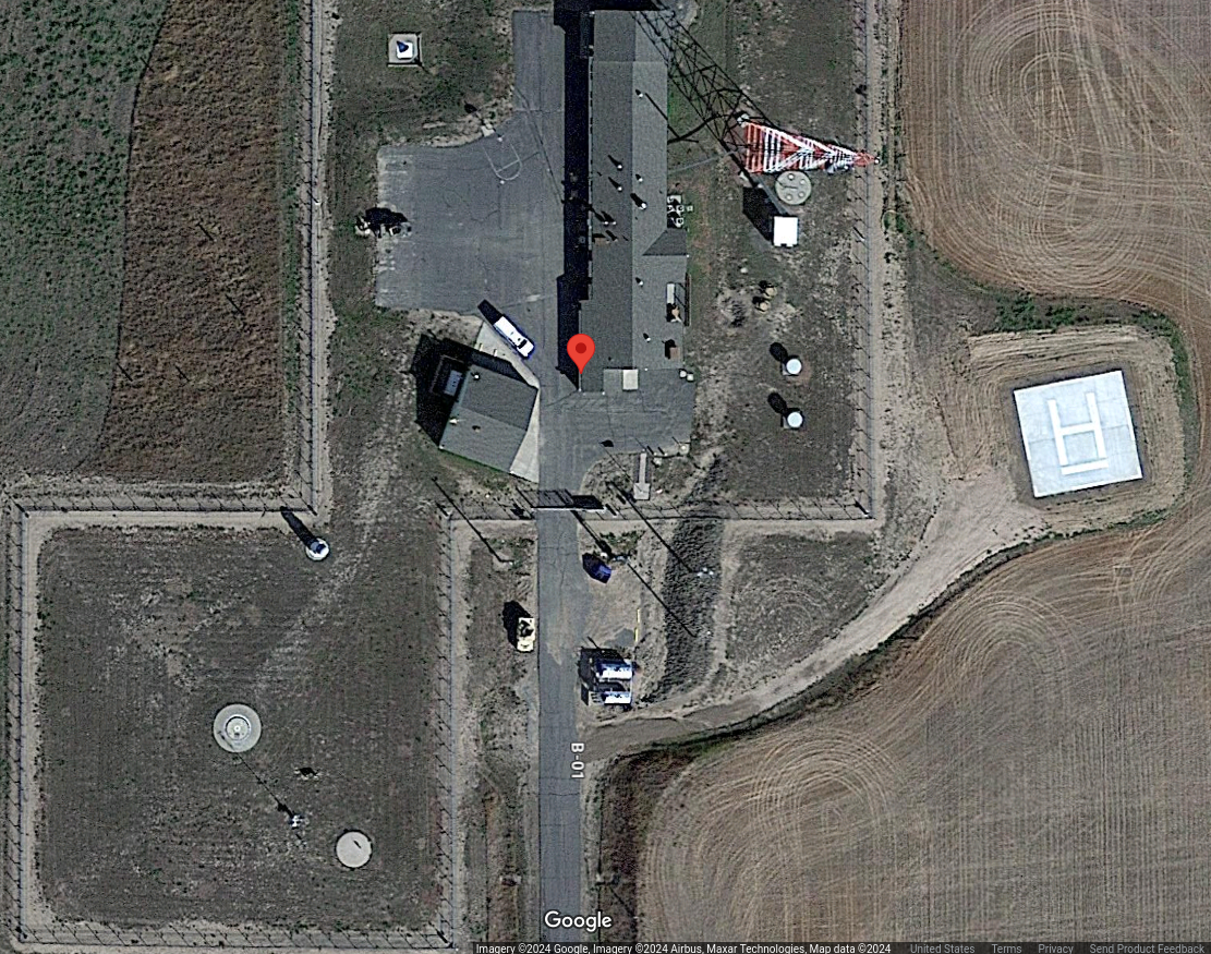
The Bravo-01 LCC for the 319th Missile Squadron. It’s not entirely clear if Minuteman LCCs still have the deployable antennas activated, but the silo for the receive antenna is clearly visible in the northeast corner below the freestanding red-on-white tower. The telescoping transmit antenna silo is the ominous bullseye in the southwest section of the facility. Source: Google Maps
To make sure the LCC is always ready to receive and act on an Emergency Alert Message (EAM), each facility has a hardened HFGCS receive antenna array. Like the transmitting antenna, these are housed in underground silos. Each silo has six monopole steel antennas, one of which is always deployed. The five others are kept in reserve; should the main antenna get knocked down, an explosive charge at the bottom of the antenna’s tube detonates, extending a fresh antenna above the ground.
Mainsail, Mainsail
Given the highly sensitive nature of the traffic on a radio network charged in part with ending the world, you’d think that messages would be digitally encrypted and completely useless to try snooping in on. And while it’s true that there are encrypted digital modes that use HFGCS, a surprising amount of traffic is just plain old voice messages transmitted in the open. While it remains true that nothing punches through like good old Morse code on continuous wave (CW), SSB voice is far more efficient. The video below shows British ham M0SZT monitoring HFGCS from an adorable shepherd’s camp somewhere in the Peak’s District, not far from the RAF Croughton HFGCS site:
That’s not to say that you’d be able to understand the messages, the bulk of which is a block of 30 numbers and letters, with the former stated as the standard NATO phonetic alphabet. Unless you have the decryption code, the message will read as gibberish. In fact, you can’t even derive any useful information from the length of the message, since it’s always 30 characters long. About the only metadata you could potentially glean would be the station code names embedded in the message, but since those are randomly changed every day, there’s not much point.
Still, there’s plenty to be gained from monitoring HFGCS, especially in times of geopolitical tumult. If the balloon goes up, so to speak, then traffic on HFGCS will undoubtedly increase markedly, as it will on its Russian counterpart, colloquially known as Bear Net to the US military. It’ll make for interesting listening — at least for a few minutes.
Good news, bad news for Sun watchers this week, as our star launched a solar flare even bigger than the one back in May that gave us an amazing display of aurora that dipped down into pretty low latitudes. This was a big one; where the earlier outburst was only an X8.9 class, the one on July 23 was X14. That sure sounds powerful, but to put some numbers to it, the lower end of the X-class exceeds 10-4 W/m2 of soft X-rays. Numbers within the class designate a linear increase in power, so X2 is twice as powerful as X1. That means the recent X14 flare was about five times as powerful as the May flare that put on such a nice show for us. Of course, this all pales in comparison to the strongest flare of all time, a 2003 whopper that pegged the needle on satellite sensors at X17 but was later estimated at X45.
So while the X14 last week was puny by comparison, it still might have done some damage if it had been Earth-directed. As it was, the flare and its associated coronal mass ejection occurred on the far side of the Sun, sending all that plasma off into the void, since pretty much all the planets were on this side of the Sun at the time. That’s the bad news part of this story, at least for those of us who enjoy watching aurora, not to mention the potential for a little doomsday. But fear not; the sunspot region that spawned this monster flare is transiting the far side of the Sun as we speak, and might just emerge with all its destructive potential intact.
Then again, why wait for the Sun to snuff communications when you can just start your own fiber optic apocalypse? Perhaps that was the motivation when saboteurs in France broke into cabinets in several locations on the night of July 28 and 29 to cut fiber cables. These must have been proper cables, since telecomms insiders say it would have taken an axe or angle grinder to cut through them. While the saboteurs were obviously motivated and organized, they appear not to have been familiar enough with the network topology to cause a widespread outage, nor did they succeed in disrupting the Paris Olympics, the most obvious nearby target. Then again, maybe they weren’t looking for that much attention. Probing attack much?
A couple of weeks back we featured a story (third item) about a GMRS system that had a questionable interaction with Federal Communications Commission investigators, resulting in their system of linked repeaters being taken offline. It seemed pretty clear to us at the time that the FCC regulations regarding the General Mobile Radio Service allowed for repeaters, but prohibited linking them together with pretty much any kind of network. Our friend Josh (KI6NAZ) over at Ham Radio Crash Course is weighing in on the issue now, and seems to have come to the same conclusion. However, the FCC didn’t really do themselves or the GMRS community any favors with the wording of 47 CFR §95.1733, which prohibits “Messages which are both conveyed by a wireline control link and transmitted by a GMRS station.” That “wireline” bit seems to be the part GMRS operators latched onto, thinking somehow that this only meant landline telephones and that linking repeaters through the Internet was all good.
A friend of ours once related his plans for the weekend, which included, “Going home, flipping on cable, and turning on CSPAN.” He knew this was pretty sad, and even had a name for it: “Loser Entertainment Television”, or LET. We’re not sure what other channels were on his LET list, but if NASA TV had been available at the time, we’re pretty sure he would have included it. Sadly, or luckily depending on your viewpoint, NASA is shutting down their cable channel in a couple of weeks. You say you had no idea that NASA had a cable channel? We didn’t either — we haven’t had cable or satellite service in at least a decade now — so don’t feel too bad. Our condolences if NASA TV was a part of your life, but you can at least take comfort that much of the same content will still be available on the NASA+ streaming service, which we also didn’t know was a thing. Are we so out of touch?
And finally, if you need something to play with during these dog days of (northern hemisphere) summer, you could do worse than React Flight Tracker, and open-source 3D visualizer for everything that flies. And we mean everything; not only does it track civil and military aviation globally, it also shows the obit of everything from satellites in LEO to dead comms birds in parking geosynchronous parking orbits. You can even zoom way out and see bits of space flotsam like boosters and fairing out about halfway to the Moon. The nice thing about it is the Google Earth-like interface, which gives you a unique perspective on flight. We always knew that the best path from Istanbul to Seattle was (almost) over the North Pole, but seeing it on a 3D globe really brings the point home. It’s also interesting to watch planes from Tokyo to Frankfurt skirting around Russian airspace. Have fun.
Of course, this isn’t a commercial product, or even a rig that’s necessarily intended for repeated use. It’s more of a tactical build, which is still pretty cool if you ask us. It started with a proof-of-concept exploration, summarized in the first video below. That’s where [Aaron] assembled and tested the major pieces, which included a PicoEMP, the bit that actually generates the high-voltage pulses intended to scramble a running microcontroller temporarily, along with a ChipWhisperer and an oscilloscope.
The trouble with the POC setup was that glitching the target chip, an LPC2388 microcontroller, involved manually scanning the business end of the PicoEMP over the package. That’s a tedious and error-prone process, which is perfect for automation. In the second video below, [Aaron] has affixed the PicoEMP to his 3D printer, giving him three-axis control of the tip position. That let him build up a heat map of potential spots to glitch, which eventually led to a successful fault injection attack and a clean firmware dump.
It’s worth noting that the whole reason [Aaron] had to resort to such extreme measures in the first place was the resilience of the target chip against power supply-induced glitching attacks. You might not need to build something like the Glitch-o-Matic, but it’s good to keep in mind in case you run up against such a hard target.
Metrology fans are usually at least a little bit in love with Mitutoyo, and rightfully so. The Japanese company has been making precision measuring instruments for the better part of 100 years, and users appreciate their precision almost as much as the silky smooth feel of their tools. If you can afford it, a Mitutoyo caliper is quite an addition to your toolbox.
As good as they are, though, they’re not perfect, which is what led to this clever Mitutoyo digital caliper hack by [turbanedengineer]. The calipers in question, a digital set from the early 1980s, happen to have a unique history with a tangential Hackaday angle — they belonged to [Dhaval], mechanical engineer and avid motorcyclist who happens to be the late elder brother of our own [Anool Mahidharia].
The tool, in need of a little TLC, made its way to [turbanedengineer] who first restored the broken battery contacts. Once powered up again, it became apparent that while the caliper’s native metric measurements were spot on, the internal conversion to inches was considerably off. This led [turbanedengineer] to the data port on the tool, which is intended to send serial data to an external computer for logging measurements. After a little experimentation to nail down the data format, he prototyped a tiny circuit using an ATtiny85 and an OLED display that reads the caliper data, converts metric to inches, and displays both measurements on the screen. The prototype led to a more permanent version, which cleverly sits over the original display and taps into the data port without any free wires. The video below shows the very slick results.
Our hearts go out to [Anool] and his family for their loss, and we tip our hats to [turbanedengineer] for his thoughtful and respectful hack of a storied tool. We know that anthropomorphizing tools makes no rational sense, but we think it’s safe to say that a tool like this has a soul, and it’s probably happy to be back in the game.
[mitxela] has a tiny problem, literally: some of his projects are so small as to defy easy programming. While most of us would probably solve the problem of having no physical space on a board to mount a connector with WiFi or Bluetooth, he took a different path and gave this clever light-based programming interface a go.
For initial experiments he wisely chose his larger but still diminutive LED matrix badge, which sports a CH32V003 microcontroller, an 8×8 array of SMD LEDs, and not much else. The video below is a brief summary of the effort, while the link above provides a much more detailed account of the proceedings, which involved a couple of false starts and a lot of prototyping that eventually led to dividing the matrix in two and ganging all the LEDs in each half into separate sensors. This allows [mitxela] to connect each side of the array to the two inputs of an op-amp built into the CH32V003, making a differential sensor that’s less prone to interference from room light. A smartphone app alternately flashes two rectangles on and off with the matrix lying directly on the screen to send data to the badge — at a low bitrate, to be sure, but it’s more than enough to program the badge in a reasonable amount of time.
We find this to be an extremely clever way to leverage what’s already available and make a project even better than it was. Here’s hoping it spurs new and even smaller LED projects in the future.
The bottom of the sea is a mysterious and inaccessible place, and anything unfortunate enough to slip beneath the waves and into the briny depths might as well be on the Moon. But the bottom of the sea really isn’t all that far away. The average depth of the ocean is only about 3,600 meters, and even at its deepest, the bottom is only about 10 kilometers away, a distance almost anyone could walk in a couple of hours.
Of course, the problem is that the walk would be straight down into one of the most inhospitable environments our planet has to offer. Despite its harshness, that environment is home to hundreds of undersea cables, all of which are subject to wear and tear through accidents and natural causes. Fixing broken undersea cables quickly and efficiently is a highly specialized field, one that takes a lot of interesting engineering and some clever hacks to pull off.
A Series of Tubes
Understanding submarine cable repairs starts with understanding the cables themselves and the challenges they face once installed. Broadly speaking, undersea cables break down into two main types: power cables and data cables. While the number of undersea power cables is rapidly increasing, mainly thanks to offshore wind farms, their cable runs tend to be shorter and to stay within relatively shallow water. Data cables, which will be the main focus of this article, tend to be long-haul cables such as those that stitch continents together and face different challenges than undersea power cables.
There are currently close to a million miles of submarine data cable in operation, almost all of which is fiber optic. That’s pretty amazing considering that copper dominated the first 120 years of submarine voice and data cable construction, and that it was only in 1988 that the first transatlantic optical cable was laid. Optical networks have obvious benefits over copper coaxial cables in terms of data throughput and reliability of the physical plant; after all, copper and seawater don’t get along very well, and water always finds a way in. The trick with fiber optics is to find a way to safely handle the hair-thin glass strands and protect them against the conditions they’ll have to endure.
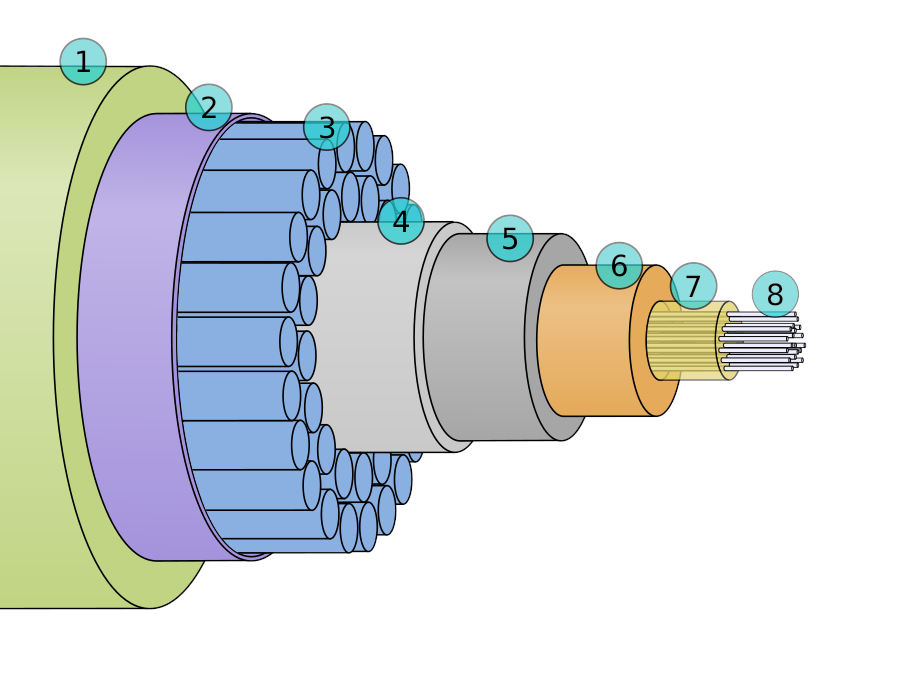
Typical double-armored submarine fiber cable. Legend: 1) Polyethylene, 2) Mylar tape, 3) Galvanized steel wires, 4) Aluminum water barrier, 5) Polycarbonate, 6) Copper or aluminum tube, 7) Petroleum jelly or silicone gel, and 8) Optical fiber pairs. Source: Oona Räisänen, public domain.
The core of a typical modern submarine cable will have multiple fiber pairs, often eight or more, with each fiber in a pair handling traffic in one direction. The fibers are bundled together in a tube made from either plastic, aluminum, or copper, with the space between the tube wall and the fibers filled with petroleum jelly or silicone gel to exclude air, which would compress at depth. This is wrapped in a polycarbonate or polyethylene jacket surrounded by a layer of galvanized steel wires wrapped in copper tape. The steel acts as armor for the fibers inside and provides mechanical strength, while the copper serves as a conductor for the high-voltage DC supplies at either end of the cable that power the inline optical repeaters that are spaced every 60 km or so. All of this is then wrapped in a thick polyethylene cover, completing the core of the cable.
Depending on the application, additional layers of armoring and protection can be added to the core. Cable destined for deep water installation with silty or sandy seafloor areas will often consist of the core alone. Cable installed in deep water but along a rockier bottom will usually get an extra wrapping of galvanized steel wires. Tougher bottom conditions and shallower water might require a cable with a double layer of armor wires or, for very challenging bottom conditions or in waters shallow enough that fishing activity or anchoring could present a hazard, a final outer armor layer may even be added. Armored cables generally have an abrasion-resistant outer wrapping of asphalt-impregnated nylon yarn.
The threat profile that a cable faces is very much dependent on depth. Close to shore, where human activity is the primary threat, installers often take the extra precaution of burying the cable. Where seabed conditions allow, cables can be buried as much as three meters deep in trenches that are dug by remotely operated plows straddling the cable and towed by the cable ship. Damage still occurs even with these precautions, with 70% or all cable casualties occurring in water less than 200 meters deep.
Once the water is deep enough to preclude anchoring, fishing, or sabotage — about a kilometer — the most likely source of damage is natural disasters such as underwater rockslides, seismic events, or volcanic activity. Even deep-sea currents are a hazard, as they can be powerful enough to move cables great distances and potentially drag them across rocks or wrecks. Whatever the cause, cable damage can range from scuffing or abrading the outer jacket enough for water to find a way inside, damaging a section of cable and gradually degrading performance to outright cleaving of the cable. It’s even possible for a long section of cable to be mysteriously removed in an apparently intentional act of sabotage.
Finding Fault
Whatever the ultimate failure mode might be, finding a fault in a cable that might be as long as the Earth’s circumference and could be 8,000 meters under the sea is no easy task. Cables typically come ashore multiple times along their length, and each landing has monitoring equipment to watch the vital signs of each segment. That isolates the fault to a specific segment of cable, but to dispatch a repair ship, the cable owner needs to pinpoint the fault as precisely as possible.
Spread-spectrum time-domain reflectometry (SS-TDR) is often used to locate and characterize a fault on active cables. Traditional time-domain reflectometry, which sends signals down a conductor to determine where any impedance discontinuities are by timing any reflections that come back from any impedance discontinuities along the way, can’t be used on in-use undersea cables thanks to the high voltages involved. SS-TDR, which was originally developed to detect faults in the wiring of airplanes using 400-Hz AC power, uses modulated pseudo-noise (PN) signals rather than a plain square wave pulse. The signals still bounce off any impedance changes introduced by damage, but an algorithm is used to correlate the returned PN codes with what was sent and when, making it easier to make measurements in a noisy environment. Optical TDR can also be used to locate fiber breaks, but since there are perhaps dozens of individual fibers inside a cable that would each have to be scanned, the fact that anything that would break one of them would likely breach the outer power conductor first makes it easier to just can that.
Once a fault is located, the cable has to be recovered. Very few cable repairs are executed on submerged cables; it’s just not the right place to open up a cable to work on it. While recovering something as small as a cable from perhaps thousands of meters below the surface seems daunting, knowing exactly where the cable was laid helps. That said, cables damaged by underwater rockslides or trawling accidents could be in a completely different spot than where they were laid, so locating the cable can be challenging. Also, some cable routes are packed with both in-service and obsolete cables; the transatlantic submarine corridor alone has dozens of cables that have to deal with the tricky topography of the Midatlantic Ridge.
While submersibles are sometimes used to identify the precise location of a cable, retrieving it is heavy work that requires heavy equipment. The cable ship travels to a point a couple of nautical miles away from the fault location and travels perpendicular to the path of the cable while dragging a cutting grapnel along the sea floor. The grapnel digs into the seabed until it snags the cable and begins lifting it. As the ship continues winching in the grapnel, the cable is forced against a cutting blade in the crotch of the grapnel, eventually severing it cleanly and completely. The cut ends fall back to the bottom where they await a second pass, this time using a special recovery grapnel. Once the first end of the cut cable is snagged, the ship’s crane winches it aboard so that a recovery buoy can be attached. This buoy marks the location of the first end, making it easier to recover later.
When both ends of the cable are hauled aboard, they make their way to the joint shop. This is an area adjacent to the “cable highway” on the ship, the cable-handling space located between the cable tanks amidship and the linear cable engine (LCE) that is used to pull cable out of the tanks and properly tension during deployment. The jointing shop has sturdy gear to secure the ends of the cable to the ship so that it doesn’t move during repairs; the cable ship also uses GPS-guided dynamic positioning thrusters to hold as precise a location as possible.
Cable technicians then get to work on repairs. If the damaged section of cable hasn’t been left on the seafloor it needs to be cut away, an arduous task for the more heavily-armored inshore cables. Once the outer jacketing and armor have been removed, the exposed fibers are ready for splicing. This is essentially the same operation as splicing terrestrial fiber optic cables; after the cladding is stripped off, the ends of the glass fiber are cleaved cleanly and positioned in the jaws of a fusion splicer. This device uses a microscope and machine vision system to precisely align the glass fibers in the gap between two tungsten electrodes before using an electric discharge to melt the fibers and fuse them together. The result is a physically and optically continuous low-loss bond.
When all the fibers have been spliced on both sides of the repair the cable is thoroughly tested. If the repairs are good, each splice is securely clamped within a joint body. This is a device engineered to both seal the spliced fibers and provide continuous mechanical support and electrical continuity. Once the joint is sealed and covered with multiple layers of polymeric waterproofing it’s ready to be returned to the seafloor. Lowering the cable is a delicate operation; you can’t just kick it over the side and hope for the best. The splice needs to be supported by a lowering yoke to reduce mechanical stress on the joint. The yoke is lowered on a cable equipped with an acoustic release hook which opens when it receives a specially coded ultrasound ping from the surface. The resulting bend in the cable is called a repair bight, which is carefully designed to respect the minimum bend radius of the cable.
Fiddle around with cars long enough and you’ll realize two things: first, anything beyond the simplest repairs will probably require some kind of specialized tool, and second, those tools can be prohibitively expensive. That doesn’t mean you’re out of luck, though, especially if you’ve got scrap galore and a DIY spirit, as this junk bin fuel injector test stand ably demonstrates.
[Desert Rat Racer]’s test rig is designed to support four injectors at once and to test them under conditions as close as possible to what they’ll experience when installed. To that end, [Rat] mounted a junk intake manifold to a stand made from scrap wood and metal found by the side of the road. A pickle jar serves as a reservoir for the test fluid — he wisely used mineral spirits as a safer substitute for gasoline — and a scrap electric fuel pump pressurizes a junk fuel rail, which distributes fuel to the injectors under test.
For testing, the injectors are wired up to an electric injector tester, which is one of the few off-the-shelf components in the build. The fuel pump and injectors are powered by the 12 volt rail of a scrapped PC power supply. Just being able to watch the spray pattern is often enough to find a faulty injector, but in case a more quantitative test is indicated, each injector is positioned over a cheap glass cylinder to catch the test fluid, and scraps of a tape measure are used to measure the depth of the collected fluid. No fancy — and expensive — graduated cylinders required.
While we truly respect the hackiness of [Desert Rat Racer]’s build, the concept of avoiding buying tactical tools is foreign to us. We understand the logic of not dropping a ton on a single-use tool, but where’s the fancy blow-molded plastic case?
What is this dystopia coming to when one of the world’s largest tech companies can’t find a way to sufficiently monetize a nearly endless stream of personal data coming from its army of high-tech privacy-invading robots? To the surprise of almost nobody, Amazon is rolling out a paid tier to their Alexa service in an attempt to backfill the $25 billion hole the smart devices helped dig over the last few years. The business model was supposed to be simple: insinuate an always-on listening device into customers’ lives to make it as easy as possible for them to instantly gratify their need for the widgets and whatsits that Amazon is uniquely poised to deliver, collecting as much metadata along the way as possible; multiple revenue streams — what could go wrong? Apparently a lot, because the only thing people didn’t do with Alexa was order stuff. Now Amazon is reportedly seeking an additional $10 a month for the improved AI version of Alexa, which will be on top of the ever-expanding Amazon Prime membership fee, currently at an eye-watering $139 per year. Whether customers bite or not remains to be seen, but we think there might be a glut of Echo devices on the second-hand market in the near future. We hate to say we told you so, but — ah, who are we kidding? We love to say we told you so.
Having Google offer to write you a check for $23 billion is pretty much the dream of every startup slogging it out in the tech trenches. Such princely offers are few and far between, but even rarer is the startup that says, “Nah, we’re good.” But that’s effectively what cloud security concern Wiz just did, rebuffing a buyout offer from Google that would roughly double the company’s current valuation, in favor of taking the company public. That’s a gutsy move, and given Google’s seeming propensity to buy technology only to sit on it or kill it off, probably a smart one.
Speaking of gutsy, one thing we never considered as a potential bottleneck to grid decarbonization is a lack of qualified wind turbine technicians. Or rather, finding people willing and able to climb hundreds of meters straight up to install, maintain, and repair the monstrous machines. It’s not exactly for everyone, but those who are willing to give it a go need proper training, and it turns out that at least one US community college has a wind turbine technician training program. Not only that, the college has a 90-meter-tall wind turbine that students can train on. It’s not a bad deal, either; a training program that costs around $10,000 dollars could help land a job paying up to $90,000 a year.
First, there was “DoS,” then we had “DDoS.” Now there’s “DDDoS” — a dog-distributed denial-of-service attack. It’s officially called NEO by the US Department of Homeland Security, which developed the system to provide law enforcement officers with protection against IoT hazards. The robot, which is built on a Boston Dynamics Spot chassis, provides a mobile observation and intelligence-gathering platform that can infiltrate an area without risking a meat-based officer. In addition to providing eyes and ears on the (hopefully) bad guys, NEO is also equipped with antennas and powerful transmitters that can swamp signals in the WiFi and cellular bands, rendering nearby nefarious wireless devices useless. We’ve heard wireless jammers are quite illegal to own or operate, so we assume there is some exception for law enforcement to use them. Or maybe it’s a “rules for thee and not for me” situation.
And finally, let your geek flag fly — on your car, at least. This collection of geeky custom license plates from MIT grads and faculty is pretty good, and shows some real creativity — especially “DSKDRV,” the plate on Samuel Klein’s floppy-festooned 1998 Honda Civic. There are some clever ideas here, and we especially like the “MITGRAD” Idaho plate, for reasons. But check out Omar Abudayyeh’s “CRISPR” plate; who knew biology could score you a ride like that?
Hacking — at least the kind where you’re breaking into stuff — is very much a learn-by-doing skill. There’s simply no substitute for getting your hands dirty and just trying something. But that doesn’t mean you can’t learn something by watching, with this root password exploit on a cheap IP video camera being a good look at the basics.
By way of background on this project, [Matt Brown] had previously torn into a VStarcam CB73 security camera, a more or less generic IP camera that he picked up on the cheap, and identified a flash memory chip from which he extracted the firmware. His initial goal was to see if the camera was contacting sketchy servers, and while searching the strings for the expected unsavory items, he found hard-coded IP addresses plus confirmation that the camera was running some Linux variant.
With evidence of sloppy coding practices, [Matt] set off on a search for a hard-coded root password. The second video covers this effort, which started with finding UART pins and getting a console session. Luckily, the bootloader wasn’t locked, which allowed [Matt] to force the camera to boot into a shell session and find the root password hash. With no luck brute-forcing the hash, he turned to Ghidra to understand the structure of a suspicious program in the firmware called encoder. After a little bit of poking and some endian twiddling, he was able to identify the hard-coded root password for every camera made by this outfit, and likely others as well.
Granted, the camera manufacturer made this a lot easier than it should have been, but with a lot of IoT stuff similarly afflicted by security as an afterthought, the skills on display here are probably broadly applicable. Kudos to [Matt] for the effort and the clear, concise presentation that makes us want to dig into the junk bin and get hacking.
Sometimes, all it takes is a change in perspective to take something boring and make it fun. That’s true about 16×2 LCD; in its usual landscape format, it’s a quick and easy way to provide a character-based display for a project. But flip it 90 degrees and use a little imagination, and it can become a cool retro racing game that fits in the palm of your hand.
[arduinocelantano] has made it a habit to press the humble 16×2 character LCD into service in ways it clearly wasn’t intended to support, such as playing Space Invaders and streaming video on it. Both of these projects seem to inform the current work, which was one of the first entries in our current Tiny Games Challenge contest. The racing game requires multiple sprites to animate the roadway and the cars, using six “layers” of eight custom characters and rapidly switching between them to create the appearance of movement. The video below has a brief sample of gameplay.
Flipping the display on its side makes for a somewhat limited game — it’s all straightaway, all the time — but that could probably be fixed. [arduinocelentano] suggests scaling it up to a 16×4 to include curves, but we’d bet you could still simulate curves on the upper part of the game field while leaving the player’s car fixed on a straight section. Higher difficulties could be achieved by moving the curved section closer to the player’s position.
Sure, it’s limited, but that’s half the charm of games like these. If you’ve got an idea for our Tiny Games Challenge, head over to our contest page and let us know about it. We’re keen to see what you come up with.
We’ve all heard about the perils of counterfeit chips, and more than a few of us have probably been bitten by those scruple-free types who run random chips through a laser marker and foist them off as something they’re not. Honestly, we’ve never understood the business model here — it seems like the counterfeiters spend almost as much time and effort faking chips as they would just getting the real ones. But we digress.
Unfortunately, integrated circuits aren’t the only parts that can be profitably faked, as [Amateur Hardware Repair] shows us with this look at questionable tantalum capacitors. In the market for some tantalums for a repair project, the offerings at AliExpress proved too tempting to resist, despite being advertised alongside 1,000 gram gold bars for $121 each. Wisely, he also ordered samples from more reputable dealers like LCSC, DigiKey, and Mouser, although not at the same improbably low unit price.
It was pretty much clear where this would be going just from the shipping. While the parts houses all shipped their tantalums in Mylar bags with humidity indicators, with all but LCSC including a desiccant pack, the AliExpress package came carefully enrobed in — plastic cling wrap? The Ali tantalums were also physically different from the other parts: they were considerably smaller, the leads seemed a little chowdered up, and the package markings were quite messy and somewhat illegible. But the proof is in the testing, and while all the more expensive parts tested fine in terms of capacitance and equivalent series resistance, the caps of unknown provenance had ESRs in the 30 milliohm range, three to five times what the reputable caps measured.
None of this is to say that there aren’t some screaming deals on marketplaces like AliExpress, Amazon, and eBay, of course. It’s not even necessarily proof that these parts were in fact counterfeit, it could be that they were just surplus parts that hadn’t been stored under controlled conditions. But you get what you pay for, and as noted in the comments below the video, a lot of what you’re paying for at the parts houses is lot tracebility.
Unless you hold a First Degree RF Wizard rating, chances are good that coax stubs seem a bit baffling to you. They look for all the world like short circuits or open circuits, and yet work their magic and act to match feedline impedances or even as bandpass filters. Pretty interesting behavior from a little piece of coaxial cable.
If you’ve ever wondered how stub filters do their thing, [Fesz] has you covered. His latest video concentrates on practical filters made from quarter-wavelength and half-wavelength stubs. Starting with LTspice simulations, he walks through the different behaviors of open-circuit and short-circuit stubs, as well as what happens when multiple stubs are added to the same feedline. He also covers a nifty online calculator that makes it easy to come up with stub lengths based on things like the velocity factor and characteristic impedance of the coax.
It’s never just about simulations with [Fesz], though, so he presents a real-world stub filter for FM broadcast signals on the 2-meter amateur radio band. The final design required multiple stubs to get 30 dB of attenuation from 88 MHz to 108 MHz, and the filter seemed fairly sensitive to the physical position of the stubs relative to each other. Also, the filter needed a little LC matching circuit to move the passband frequency to the center of the 2-meter band. All the details are in the video below.
It’s pretty cool to see what can be accomplished with just a couple of offcuts of coax. Plus, getting some of the theory behind those funny little features on PCBs that handle microwave frequencies is a nice bonus. This microwave frequency doubler is a nice example of what stubs can do.
When monitors around the world display a “Blue Screen of Death” and you know it’s probably your fault, it’s got to be a terrible, horrible, no good, very bad day at work. That’s likely the situation inside CrowdStrike this weekend, as engineers at the cybersecurity provider struggle to recover from an update rollout that went very, very badly indeed. The rollout, which affected enterprise-level Windows 10 and 11 hosts running their flagship Falcon Sensor product, resulted in machines going into a boot loop or just dropping into restore mode, leaving hapless millions to stare at the dreaded BSOD screen on everything from POS terminals to transit ticketing systems.
Tales of woe from the fallout from what’s being called “the largest IT outage in history” are pouring in, including this very bewildered game developer who while stranded at an airport had plenty of ponder about why CrowdStrike broke the cardinal rule of software development by rolling a change to production on a Friday. The good news is that there’s a workaround, but the bad news is that someone has to access each borked machine and manually delete a file to fix it. Current estimates place the number of affected machines at 8.5 million, so that’s a lot of legwork. There’s plenty of time after the fix is rolled out for a full accounting of the impact, including the search for the guilty and persecution of the innocent, but for now, let’s spare a moment’s pity for the devs who must be sweating things out this weekend.
Back in 2011, Craig Fugate of the Federal Emergency Management Agency said of disaster response in the southern US, “If you get there and the Waffle House is closed? That’s really bad.” Thus was born the “Waffle House Index,” an informal measure of a natural disaster’s impact based on where individual restaurants in the chain that prides itself on always being open are actually up and running. With over 1,900 locations in 25 states, you’d think it would cover just about any emergency, but desperate Texans eschewed the index during the recent extensive power outages in the Houston area caused by Hurricane Beryl by inventing the “Whattaburger Index.” We haven’t had the pleasure of this particular delicacy, but it seems Texans can’t get enough of the hamburger chain, enough so that their online app’s location map provides a pretty granular view of a wide swathe of Texas. Plus, the chain thoughtfully color-codes each location’s marker by whether it’s currently open or closed, making it a quick and easy way to check where the power is on or off — at least during regular business hours. Hat’s off to the enterprising Texans who figured this out, and here’s hoping that life has returned to normal for everyone by now.
While we’re generally not fans of Apple products, which seem overpriced and far too tightly controlled for our liking, we’ve been pretty impressed by some of the results people have reported using their Apple AirTags to recover lost or stolen items — this recent discovery of a cache of stolen tools (fourth item) comes to mind. Results such as that require a “me too” response from the Android side of the market, resulting in the Find My Device network that, perhaps unsurprisingly, doesn’t appear to work very well. The test was pretty much what you’d expect — drop an Android-compatible tag in the mail along with an AirTag and track their journey. The Android tag only reported in a couple of times, while the AirTag provided a comprehensive track of the parcel’s journey through the USPS. Our first thought is that this speaks mostly to the power of being first to market, allowing Apple to have a more completely built-out infrastructure. But this may say more about the previously mentioned flexibility of Android compared to Apple; we know we noped the hell out of participating in Find My Device as soon as it rolled out on our Android phone. Seems like a lot of Android users feel the same way.
And finally, while we haven’t checked out comments on this week’s podcast, we’re pretty sure we’re getting raked over the coals for betraying our ignorance of and lack of appreciation for the finer points of soccer, or football. Whatever you call it, we just don’t get it, but we do understand and agree with our own Lewin Day’s argument that instrument-enhanced officiating isn’t making the game any better. Our argument is that in any sport, the officials are like a third team, one that’s adversarial to both of the competing teams, hopefully equally so, and that giving them super-human abilities isn’t fair to the un-enhanced players on the field/pitch/court/ice. So it was with considerable dismay that we learned that Major League Baseball is experimenting with automatic umpires to call balls and strikes behind the plate. While you may not care about baseball, you have to appreciate the ability of an umpire to stand directly in the line of fire of someone who can hurl a ball fast enough to hit a strike zone about the size of a pizza box the ball in less than 500 milliseconds. Being able to determine if the ball ended up in or out of that box is pretty amazing, not to mention all the other things an umpire has to do to make sure the game is played by the rules. They’re not perfect, of course, and neither are the players, and half the fun of watching sports for us is witnessing the very human contest of wills and skills of everyone involved. It seems like a bad idea to take the humans out of that particular loop.
Can you weld wood? It seems like a silly question — if you throw a couple of pieces of oak on the welding table and whip out the TIG torch, you know nothing is going to happen. But as [Action Lab] shows us in the video below, welding wood is technically possible, if not very practical.
Since experiments like this sometimes try to stretch things a bit, it probably pays to define welding as a process that melts two materials at their interface and fuses them together as the molten material solidifies. That would seem to pose a problem for wood, which just burns when heated. But as [Action Lab] points out, it’s the volatile gases released from wood as it is heated that actually burn, and the natural polymers that are decomposed by the heat to release these gases have a glass transition temperature just like any other polymer. You just have to heat wood enough to reach that temperature without actually bursting the wood into flames.
His answer is one of the oldest technologies we have: rubbing two sticks together. By chucking a hardwood peg into a hand drill and spinning it into a slightly undersized hole in a stick of oak, he created enough heat and pressure to partially melt the polymers at the interface. When allowed to cool, the polymers fuse together, and voila! Welded wood. Cutting his welded wood along the joint reveals a thin layer of material that obviously underwent a phase change, so he dug into this phenomenon a bit and discovered research into melting and welding wood, which concludes that the melted material is primarily lignin, a phenolic biopolymer found in the cell walls of wood.
[Action Lab] follows up with an experiment where he heats bent wood in a vacuum chamber with a laser to lock the bend in place. The experiment was somewhat less convincing but got us thinking about other ways to exclude oxygen from the “weld pool,” such as flooding the area with argon. That’s exactly what’s done in TIG welding, after all.